
Image not available
Illustrative purposes only

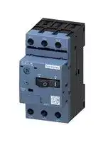
3RV1011-1FA15
Thermal Magnetic Circuit Breaker, MPCB, 3RV1, 3P, 100 kA, 400 V, 5 A, Auxiliary Switch 1NO+1NC
⚠️ Reference pricing provided. In case of supply shortages, we will connect you with our trusted procurement partners to ensure your project's continuity.
- Manufacturer: SIEMENS
- Product type:
- Product Range: SIRIUS 3RV1 Series
| Delivery and price | |
|---|---|
| Units per pack | 1 |
| Price | 104.4 € |
| Current stock | 10+ |
| Lead time | 30 days |
Datasheet

**3RV1011-1FA15**

**Data sheet**

Circuit breaker size S00 for motor protection, CLASS 10 A-release 3.5...5 A N release 65 A 1 NO+1 NC transverse Screw terminal Standard switching capacity

||Circuit breaker size S00 for motor protection, CLASS 10 A-release 3.5...5 A N<br>release 65 A 1 NO+1 NC transverse Screw terminal Standard switching capacity|
|---|---|
|**product brand name**|SIRIUS|
|**product designation**|Circuit breaker|
|**design of theproduct**|For motorprotection|
|**product type designation**|3RV1|
|**General technical data**<br>~~Se~~||
|**Product equipment of circuit breaker for motor protection**<br>**complete unit withprotection device**<br>~~Se~~|Yes<br>~~Se~~|
|**size of the circuit-breaker**|S00|
|**size of contactor can be combined company-specific**|S00|
|product function disconnector functionality|Yes|
|product extension auxiliaryswitch|Yes|
|**power loss[W] for rated value of the current**||
|● at AC in hot operatingstate|7.25 W|
|● at AC in hot operatingstateperpole|2.4 W|
|**type of calculation ofpower loss current-dependent**|quadratic|
|insulation voltage with degree ofpollution 3 at AC rated value|690 V|
|**surge voltage resistance rated value**|6 kV|
|**maximumpermissible voltage forprotective separation**||
|● in networks with ungrounded star point between main and<br>auxiliarycircuit|400 V|
|● in networks with grounded star point between main and<br>auxiliarycircuit|400 V|
|**protection class IP**||
|● on the front accordingto IEC 60529|IP20|
|● on the front|IP20|
|● of the terminal|IP00|
|**mechanical service life(operating cycles)**||
|● of the main contacts typical|100 000|
|● of auxiliarycontacts typical|100 000|
|electrical endurance(operatingcycles)typical|100 000|
|**reference code according to IEC 81346-2**|Q|
|**continuous current rated value**|5 A|
|**Substance Prohibitance(day/month/year)**|01/01/2013|
|**Net Weight**|295g|
|**Ambient conditions**<br>~~Se~~||
|installation altitude at height above sea level maximum<br>~~Se~~|2 000 m<br>~~Se~~|
|**ambient temperature**||
|● duringoperation|-20 ... +60 °C|
|● duringstorage|-50 ... +80 °C|
|● during transport|-50 ... +80 °C|


Subject to change without notice © Copyright Siemens

3RV10111FA15 Page 1/7

5/31/2026

|**temperature compensation**|-20 ... +60 °C|
|---|---|
|relative humidityduringoperation|10 ... 95 %|
|**Main circuit**||
|**number ofpoles for main current circuit**|3|
|**adjustable current response value current of the current-**<br>**dependent overload release**|3.5 ... 5 A|
|**type of voltage for main current circuit**|AC|
|**operating voltage**||
|● rated value|690 V|
|● rated value|20 ... 690 V|
|● at AC-3 rated value maximum|690 V|
|● at AC-3e rated value maximum|690 V|
|**operating frequency rated value**|50 ... 60 Hz|
|**operational current rated value**|5 A|
|**operational current**||
|● at AC-3 at 400 V rated value|5 A|
|● at AC-3e at 400 V rated value|5 A|
|**operating power**||
|● at AC-3||
|— at 230 V rated value|1.1 kW|
|— at 400 V rated value|1.5 kW|
|— at 500 V rated value|2.2 kW|
|— at 690 V rated value|4 kW|
|● at AC-3e||
|— at 230 V rated value|1.1 kW|
|— at 400 V rated value|1.5 kW|
|— at 500 V rated value|2.2 kW|
|— at 690 V rated value|4 kW|
|**operating frequency**||
|● at AC-3 maximum|15 1/h|
|● at AC-3e maximum|15 1/h|
|**Auxiliary circuit**||
|**design of the auxiliary switch**|transverse|
|**type of voltage for auxiliary and control circuit**|AC/DC|
|**number of NC contacts for auxiliary contacts**|1|
|**number of NO contacts for auxiliary contacts**|1|
|number of CO contacts for auxiliarycontacts|0|
|**operational current of auxiliary contacts at AC-15**||
|● at 24 V|2 A|
|● at 110 V|2 A|
|● at 120 V|2 A|
|● at 125 V|2 A|
|● at 230 V|0.5 A|
|**operational current of auxiliary contacts at DC-13**||
|● at 24 V|1 A|
|● at 60 V|0.15 A|
|**Protective and monitoring functions**||
|**product function**||
|●ground fault detection|No|
|●phase failure detection|Yes|
|**trip class**|CLASS 10|
|**design of the overload release**|thermal|
|**protection function thermal overloadprotection(ANSI 49)**|Yes|
|**maximum short-circuit current breaking capacity (Icu)**||
|● at AC at 240 V rated value|100 kA|
|● at AC at 400 V rated value|100 kA|
|● at AC at 500 V rated value|3 kA|
|● at AC at 690 V rated value|2 kA|
|**operating short-circuit current breaking capacity (Ics) at AC**||


Subject to change without notice © Copyright Siemens

3RV10111FA15 Page 2/7

5/31/2026

||● at 240 V rated value|100 kA||
|---|---|---|---|
||● at 400 V rated value|100 kA||
||● at 500 V rated value|3 kA||
||● at 690 V rated value|2 kA||
||response value current of instantaneous short-circuit trip unit|65 A||
||**UL/CSA ratings**|||
||**full-load current(FLA) for 3-phase AC motor**|||
||● at 480 V rated value|5 A||
||● at 600 V rated value|5 A||
||**yielded mechanicalperformance[hp]**|||
||● for single-phase AC motor|||
||— at 110/120 V rated value|0.17 hp||
||— at 230 V rated value|0.5 hp||
||● for 3-phase AC motor|||
||— at 200/208 V rated value|1 hp||
||— at 220/230 V rated value|1 hp||
||— at 460/480 V rated value|3 hp||
||— at 575/600 V rated value|3 hp||
||**contact rating of auxiliary contacts according to UL**|C300 / R300||
||**Short-circuit protection**|||
||**product function short circuitprotection**|Yes||
||**design of the short-circuit trip**|magnetic||
||**design of the fuse link**|||
||● for short-circuitprotection of the auxiliaryswitch required|fusegG: 10 A, miniature circuit breaker C 6 A(short-circuit current Ik < 400 A)||
||**design of the fuse link for IT network for short-circuit**<br>**protection of the main circuit**|||
||● at 240 V|none required||
||● at 400 V|gG 50 A||
||● at 500 V|gG 35 A||
||● at 690 V|gG 35 A||
||certificate of suitabilityaccordingto ATEX directive 2014/34/EU|DMT 02 ATEX F 001||
||**type of protection according to ATEX directive 2014/34/EU**|Ex II(2)GD||
||**Installation/ mounting/ dimensions**|||
||**mounting position**|any||
||**fastening method**|screw and snap-on mountingonto 35 mm DIN rail accordingto DIN EN 60715||
||**Mounting method of circuit breaker for Transformer**<br>**protection, Generator protection and system protection**<br>**optional standard bar mounting**|Yes||
||**height**|90 mm||
||**width**|45 mm||
||**depth**|75 mm||
||**required spacing**|||
||● forgroundedparts at 400 V|||
||— downwards|20 mm||
||— upwards|20 mm||
||— at the side|9 mm||
||● for liveparts at 400 V|||
||— downwards|20 mm||
||— upwards|20 mm||
||— at the side|9 mm||
||● forgroundedparts at 500 V|||
||— downwards|20 mm||
||— upwards|20 mm||
||— at the side|9 mm||
||● for liveparts at 500 V|||
||— downwards|20 mm||
||— upwards|20 mm||
||— at the side|9 mm||
||● forgroundedparts at 690 V|||
||— downwards|20 mm||


Subject to change without notice © Copyright Siemens

3RV10111FA15 Page 3/7

5/31/2026

|— upwards|20 mm|
|---|---|
|— backwards|0 mm|
|— at the side|9 mm|
|— forwards|0 mm|
|● for liveparts at 690 V||
|— downwards|20 mm|
|— upwards|20 mm|
|— backwards|0 mm|
|— at the side|9 mm|
|— forwards|0 mm|
|**Connections/ Terminals**||
|**product component removable terminal for auxiliary and**<br>**control circuit**|No|
|**type of electrical connection**||
|● for main current circuit|screw-type terminals|
|● for auxiliaryand control circuit|screw-type terminals|
|**arrangement of electrical connectors for main current**<br>**circuit**|Top and bottom|
|**type of connectable conductor cross-sections**||
|● for main contacts||
|— solid or stranded|2x(0,5 ... 1,5 mm²), 2x(0,75 ... 2,5 mm²), 2x(1 ... 4 mm²)|
|— finelystranded with core endprocessing|2x(0.5 ... 1.5 mm²), 2x(0.75 ... 2.5 mm²)|
|**connectable conductor cross-section for main contacts**||
|● solid or stranded|0.5 ... 4 mm²|
|● finelystranded with core endprocessing|0.5 ... 2.5 mm²|
|**connectable conductor cross-section for auxiliary contacts**||
|● solid or stranded|0.5 ... 2.5 mm²|
|● finelystranded with core endprocessing|0.5 ... 2.5 mm²|
|**type of connectable conductor cross-sections**||
|● for auxiliarycontacts||
|— solid or stranded|2x(0.5 ... 1.5 mm²), 2x(0.75 ... 2.5 mm²)|
|**AWG number as coded connectable conductor cross**<br>**section for main contacts**|18 ... 14|
|**AWG number as coded connectable conductor cross**<br>**section for auxiliary contacts**|18 ... 14|
|**tightening torque**||
|● for main contacts with screw-type terminals|0.8 ... 1.2 N·m|
|● for auxiliarycontacts with screw-type terminals|0.8 ... 1.2 N·m|
|**design of screwdriver shaft**|Diameter 5 to 6 mm|
|**size of the screwdriver tip**|Pozidriv size 2|
|**design of the thread of the connection screw**||
|● for main contacts|M3|
|● of the auxiliaryand control contacts|M3|
|**Safety related data**||
|product function suitable for safetyfunction|Yes|
|**suitability for use**||
|● safety-related switchingon|No|
|● safety-related switchingOFF|Yes|
|**service life maximum**|10 a|
|**test wear-related service life necessary**|Yes|
|**proportion of dangerous failures**||
|● with low demand rate accordingto SN 31920|40 %|
|● with high demand rate accordingto SN 31920|50 %|
|**B10 value with high demand rate according to SN 31920**|5 000|
|**failure rate [FIT] with low demand rate according to SN**<br>**31920**|50 FIT|
|ISO 13849||
|**device type according to ISO 13849-1**|3|
|**overdimensioning according to ISO 13849-2 necessary**|Yes|
|IEC 61508||


Subject to change without notice © Copyright Siemens

3RV10111FA15 Page 4/7

5/31/2026

**==> picture [520 x 623] intentionally omitted <==**

**----- Start of picture text -----**<br>
safety device type according to IEC 61508-2 Type A<br>nl Electrical Safety<br>protection class IP on the front according to IEC 60529 IP20<br>touch protection on the front according to IEC 60529 finger-safe, for vertical contact from the front<br>a Display<br>display version for switching status Rocker switch<br>a Approvals Certificates<br>Environment General Product Approval<br>Environmental Con-<br>— firmations<br>[eA ce<br>General Product Ap- For use in hazardous locations Test Certificates Maritime application<br>proval<br>- -<br>Type Test Certific Special Test Certific<br>ates/Test Report ate<br>Maritime application other<br>Miscellaneous<br>o ip _<br>a us = os Si i<br>other Railway<br>Confirmation Miscellaneous Special Test Certific-<br>ate<br>QC PASS<br>ns<br>e Further information e<br>Information on the packaging<br>https://support.industry.siemens.com/cs/ww/en/view/109813875<br>Information for data generation and storage<br>https://support.industry.siemens.com/cs/ww/en/view/109995012<br>Information- and Downloadcenter (Catalogs, Brochures,…)<br>https://www.siemens.com/ic10<br>Industry Mall (Online ordering system)<br>https://mall.industry.siemens.com/mall/en/en/Catalog/product?mlfb=3RV1011-1FA15<br>Service&Support (Manuals, Certificates, Characteristics, FAQs,...)<br>https://support.industry.siemens.com/cs/ww/en/ps/3RV1011-1FA15<br>Image database (product images, 2D dimension drawings, 3D models, device circuit diagrams, EPLAN macros, ...)<br>https://www.automation.siemens.com/bilddb/cax_de.aspx?mlfb=3RV1011-1FA15&lang=en<br>Cax online generator<br>https://support.automation.siemens.com/WW/CAXorder/default.aspx?lang=en&mlfb=3RV1011-1FA15<br>Characteristic curves<br>https://curves.simaris.siemens.com/curves/<mmp_prod_noCOMP="HAUPT"></mmp_prod__no><br>**----- End of picture text -----**<br>


Subject to change without notice © Copyright Siemens

3RV10111FA15 Page 5/7

5/31/2026

**==> picture [381 x 260] intentionally omitted <==**

**----- Start of picture text -----**<br>
-F<br>[|| _<br>Tapas<br>I> I> I><br>13 21<br>1/L1 3/L2 5/L3<br>/T1 /T2 /T3 14 22<br>2 4 6<br>**----- End of picture text -----**<br>


**last modified:**

5/5/2026

Subject to change without notice © Copyright Siemens

3RV10111FA15 Page 6/7

5/31/2026

Subject to change without notice © Copyright Siemens

3RV10111FA15 Page 7/7

5/31/2026
Updated at March 30, 2026
About Novapart
Novapart is a B2B electronic component broker specialising in stock shortages and cost reduction. We source hard-to-find parts and identify compliant alternatives across a catalogue of 410,000+ components from 500+ manufacturers.
Learn more →Stock Shortage Specialist
When a component is unavailable, discontinued or has an unacceptable lead time, we tap into our network of vetted European and Asian distributors to source what you need — without compromising on quality or traceability.
Request a quote →Compliant Alternatives
We identify pin-to-pin, electrically equivalent substitutes that meet the same certifications (RoHS, AEC-Q100, REACH) as your original specification — validated against datasheets, not just part numbers. Often at a lower cost.
BOM Analysis service →