
Image not available
Illustrative purposes only

3130-FA2A-P7T1-W01Q-15A-A040001M
Thermal Circuit Breaker, 3130, 15 A, 2 Pole, 50 V, 250 V, Panel
⚠️ Reference pricing provided. In case of supply shortages, we will connect you with our trusted procurement partners to ensure your project's continuity.
- Manufacturer: ETA
- Product type: Thermal Circuit Breakers
- No. of Poles: 2 Pole
- Product Range: 3130
- Current Rating: 15A
- Voltage Rating VAC: 250V
- Circuit Breaker Mounting: Panel
| Delivery and price | |
|---|---|
| Units per pack | 20 |
| Price | 26.63 € |
| Current stock | 10+ |
| Lead time | 30 days |
Datasheet

**Thermal Overcurrent Circuit Breaker 3130**
## **Description**
Single, two and three pole rocker switch/thermal trip free circuit breakers (S-type TO CBE to EN 60934) of compact design for snap-in panel mounting. Available either with protection on one/both/all poles or, in the case of the double pole version, protection on one pole only. Illumination is optional and there is a choice of rocker colours. Approved to CBE standard EN 60934 (IEC 60934).
## **Typical applications**
Motors, transformers, solenoids, household and office machines, electrical tools, mobile homes, boating, construction vehicles, medical equipment to EN 60601.
**==> picture [147 x 18] intentionally omitted <==**
**----- Start of picture text -----**<br>
3130<br> 1-pole 3-pole<br>**----- End of picture text -----**<br>
## **Standard current ratings and typical internal resistance values**
## **Technical data**
||**Current**|**Internal resistance**|**Internal resistance**|**Internal resistance**|**Current**|**Current**|**Internal resistance**|**Internal resistance**|||||
|---|---|---|---|---|---|---|---|---|---|---|---|---|
||**rating (A)**|**per pole (Ω)**|**per pole (Ω)**||**rating (A)**||**per pole (Ω)**||**For further detailsplease see chapter: Technical Information**||||
||0.1|94|||4||0.0435||Voltage rating|||AC 240 V; 3 AC 415 V; DC 50 V<br>(UL: AC 250 V;3 AC 250 V;DC 50 V)|
||0.2|24|||5||0.0325||Current ratings|Current ratings||0.1...20 A 1-pole|
||0.3|12|||6||0.0215|||||0.1...16 A 2- and 3-pole|
||0.4|5.30|||7||0.0165||Typical life<br>AC 240 V:<br>0.1...20 A 30,000 operations at 1 x I||0.1...20 A 30,000 operations at 1 x I|**1-pole**<br>0.1...20 A 30,000 operations at 1 x IN, inductive|
||0.5|4.20|||8||0.0165||DC 50 V:<br>0.1...4 A|||30,000 operations at 1 x IN, inductive|
||||||||||4.5...16 A 30,000 operations at 1 x I||4.5...16 A 30,000 operations at 1 x I|4.5...16 A 30,000 operations at 1 x IN, resistive|
||0.8|1.50|||10||< 0.02|< 0.02|DC 28 V:<br>0.1...20 A 30,000 operations at 1 x I||0.1...20 A 30,000 operations at 1 x I|0.1...20 A 30,000 operations at 1 x IN, inductive|
||1|0.9|||12||< 0.02||AC 240 V:<br>0.1...16 A 50,000 operations at 1 x I||0.1...16 A 50,000 operations at 1 x I|**2-pole**<br>0.1...16 A 50,000 operations at 1 x IN, inductive|
||1.2|0.80|||14||< 0.02||DC 50 V:<br>0.1...16 A 50,000 operations at 1 x I||0.1...16 A 50,000 operations at 1 x I|0.1...16 A 50,000 operations at 1 x IN, inductive|
|||||||||||||**3-pole**|
||1.5|0.45|||15||< 0.02||3 AC 415 V: 0.1...16 A 30||3 AC 415 V: 0.1...16 A 30|3 AC 415 V: 0.1...16 A 30,000 operations at 1 x IN,inductive|
||2|0.27|||16||< 0.02||Ambient temperature -30...+60 °C||erature -30...+60 °C|erature -30...+60 °C(-22...+140 °F)|
||2.5|0.0785|||18||< 0.02||Insulation co-ordination<br>(IEC 60664 and 60664 A) withstand voltage|||rated impulse<br>pollution<br>(IEC 60664 and 60664 A) withstand voltage<br>degree|
||3|0.0595|||20||< 0.02|||||2.5 kV<br>2|
|reinforced insulation in operatingarea<br>Dielectric strength<br>(IEC 60664 and 60664A)<br>test voltage<br>operating area AC 3,000 V<br>currentpath/currentpath AC 1,500 V<br>Insulation resistance<br>> 100 MΩ(DC 500 V)<br>Interrupting capacity Icn<br>0.1...2 A<br>10 x IN<br>2.5...20 A<br>150 A<br>1-pole<br>2.5...16 A<br>250 A<br>2-pole<br>2.5...12 A<br>150 A<br>3-pole<br>14 + 16 A<br>130 A<br>3-pole<br>Interrupting capacity (UL 1077)<br>Degree of protection<br>operating area IP40<br>**Illumination voltage/power consumption**<br>3.5<br>0.0565<br>IN<br>UN<br>Inc<br>1, 2-pole<br>0.1...16 A<br>AC 250 V<br>3500 A<br>3-pole<br>0.1...12 A<br>3 AC 250 V<br>5000 A<br>1,2-pole<br>0.1...16 A<br>DC 50 V<br>2000 A<br>**operating voltage**<br>**power consumption**<br>1-pole<br>2-/3-pole<br>2-/3-pole<br>**Y+R**<br>**G**<br>12 V<br>9 mA<br>2 mA<br>3.5 mA<br>24 V<br>9 mA<br>2 mA<br>3.5 mA<br>48 V<br>9 mA<br>2 mA<br>3.5 mA<br>115 V<br>< 1 mA<br>0.9 mA<br>2.8 mA<br>230 V<br>< 1 mA<br>0.9 mA<br>2.8 mA<br>400 V<br>-<br>0.9 mA<br>2.8 mA<br>~~=~~|||||||||||||
||||||||||(IEC 60529/DIN 40050)terminal area IP00||terminal area IP00|terminal area IP00|
||||||||||Vibration|||5 g (57-500 Hz) ± 0.38 mm (10-57 Hz)|
|||||||||||||to IEC 60068-2-6, test Fc|
|||||||||||||10 frequencycycles/axis|
||||||||||Shock|||1-pole: 25 g (11 ms) 2 + 3-pole: 20 g (11 ms)|
|||||||||||||to IEC 60068-2-27,test Ea|
||||||||||Corrosion|Corrosion||96 hours at 5 % salt mist,|
|||||||||||||to IEC 60068-2-11,test Ka|
||||||||||Humidity|Humidity||240 hours at 95 % RH,|
|||||||||||||to IEC 60068-2-78,test Cab|
||||||||||Mass|||approx. 45 g (three pole)|
|||||||||||||approx. 31 g (double pole)|
|||||||||||||approx. 17g (singlepole)|
||1815|||||||**www.e-t-a.de**||||1|
**Thermal Overcurrent Circuit Breaker 3130**
## **Ordering information - 1-pole**
**Type No. 3130** single pole thermal circuit breaker **Mounting F** snap in frame **Frame 1** standard **Number of poles 1** single pole, thermally protected **Frame mounting 0** panel thickness 1-2.5 mm (.039-.099 in) **Terminal design P7** blade terminals DIN 46244-C-Ms-S (QC 2x.110) **H7** for terminals 1.1, 2.1 3.1 terminal screws M 3.5 for terminals 1.2, 2.2, 3.2 blade terminals (QC 2x.110) **Characteristic curve T1** thermal 1.05-1.4 IN **Actuator style W** rocker switch with marking „I“ and „O“ moulded in **Actuator colour 01 Q** black opaque without illumination **02 Q** white opaque without illumination **04 Q** red opaque without illumination **14 Q R** red translucent with LED-illumination **15 Q Y** orange translucent with LED-illumination **19 Q G** green translucent with LED-illumination (DC only) **Illumination voltage range** * **2** 10 - 14 V DC **3** 20 - 28 V DC **6** 90 - 140 V AC **7** 185 - 275 V AC **Current ratings 0,1...20 A 3130 - F 1 1 0 - P7 T1 - W 14 Q R 3 - 5 A** ordering example
- N/A for non-illuminated version
## **Ordering information - multipole**
**Type No. 3130** multipole thermal circuit breaker **Mounting F** snap in frame **Frame 1** standard **A** version for X3130 **Number of poles 2** 2-pole thermally protected **3** 3-pole thermally protected **5** 2-pole, 1-pole thermally protected **Frame mounting 0** panel thickness 1-2.5 mm (.039-.099 in) **A** 2-pole, version for X3130 **Terminal design P7** blade terminals DIN 46244-C-Ms-S (characteristic curve T1) **H7** for terminals 1.1, 2.1 3.1 terminal screws M 3.5 for terminals 1.2, 2.2, 3.2 blade terminals (QC 2x.110) **Characteristic curve T1** thermal 1.05-1.4 IN **Actuator style W** rocker switch with marking „I“ and „O“ moulded in **Actuator colour 01 Q** black opaque without illumination **02 Q** white opaque without illumination **04 Q** red opaque without illumination **14 Q R** red translucent with LED-illumination **15 Q Y** orange translucent with LED-illumination **19 Q G** green translucent with LED-illumination **Illumination voltage range** * **2** 10 - 14 V DC **3** 20 - 28 V DC **6** 90 - 140 V AC **7** 185 - 275 V AC **8** 320 - 450 V AC **Current ratings 0,1...16 A**
## **Preferred types**
**3130 - F 1 3 0 - P7 T1 - W 14 Q R 7 - 5 A** ordering example
|**Preferred types**<br>**3130 1-pole**|**Standard current ratings (A)**|**Standard current ratings (A)**|**Standard current ratings (A)**|**Standard current ratings (A)**|**Standard current ratings (A)**|**Standard current ratings (A)**|**Standard current ratings (A)**|**Standard current ratings (A)**|**Standard current ratings (A)**|**Standard current ratings (A)**|
|---|---|---|---|---|---|---|---|---|---|---|
||**1**|**2**|**3**|**4**|**5**|**8**|**10**|**15**|**16**|**20**|
|3130-F110-P7T1-<br>W01Q-|x|x|x|x|x|x|x|x|x|x|
- N/A for non-illuminated version
## **Approvals**
|**Authority**|**Standard**|**Rated voltage**|**Current ratings**|
|---|---|---|---|
|VDE|IEC/EN<br>60934|AC 240 V<br>AC 240/415 V<br>DC 50 V<br>DC 50 V<br>DC 28 V|0.1 A…20 A (single pole)<br>0.1 A…16 A (multipole)<br>0.1 A…8 A (single pole)<br>0.1 A…16 A (multipole)<br>0.1 A…20 A(singlepole)|
|UL|UL 1077|AC 250 V<br>AC 250 V<br>DC 50 V|0.1 A…16 A (1 + 2 pole)<br>0.1 A…12 A (3 pole)<br>0.1 A…16 A(1 – 3pole)|
|CSA|C22.2 No<br>235|AC 250 V<br>AC 250 V<br>DC 50 V|0.1 A…16 A (1 + 2 pole)<br>0.1 A…12 A (3 pole)<br>0.1 A…16 A(1 – 3pole)|
**www.e-t-a.de**
2
1815
**Thermal Overcurrent Circuit Breaker 3130**
## **Dimensions**
**==> picture [511 x 658] intentionally omitted <==**
**----- Start of picture text -----**<br>
3130-F110-… 3130-F130-… 37.5<br>14.5 1.48<br>OFF ON 32.5<br>OFF ON .571 9.5 1.28<br>.374<br>terminal for<br>illumination<br>conductor size<br>0.14 mm [2] (AWG26),<br>length 180 mm<br>(7.09 in.)<br>LINE<br>LINE I.3 I.2 I.I<br>I.3 I.2 I.I<br>2 3 2 I unit<br>.079202 blade terminals DIN 46244-C-Ms-S(QC 2x.110 P7 or N7) .07920 blade terminals DIN 46244-C-Ms-S(QC 2x.110 P7 or N7)<br>34.787 Side view 34.787 Side view<br>1.34<br>1.34<br>switch only LINE<br>LINE I.I<br>I.I<br>flat head screw M3.5x5 -MS ISO 1580 (H7) Panel cut-out<br>flat head screw M3.5x5 -MS ISO 1580 (H7)tightening torque max. 0.8 Nm Panel cut-out tightening torque max. 0.8 Nm -.016-0.4-0.2 min. 1.5min .059<br>-.016-0.4-0.2 min. 1.5min .059 ±-.0080.1<br>-.008 ±.004<br>±0.1 panel thickness<br>±.004 1-2.5 mm 34 [+0.2]<br>panel thickness (.039-.098 in.) 1.34 [+.008]<br>1-2.5 mm 34 [+0.2]<br>36<br>1.42 (.039-.098 in.) 1.34 [+.008] +0.3+.012<br>optional illumination +0.3 36<br>+.012 1.42<br>optional illumination<br>Edges of working parts: DIN 6784<br>3130-F120-…<br>26<br>1.02<br>OFF ON 21<br>.827 Internal connection diagrams<br>1-pole 2-pole<br>line 1.1 line 1.1 2.1<br>LINE<br>I.3 I.2 I.I<br>2 2 I unit 1.3<br>.079 blade terminals DIN 46244-C-Ms-S<br>20 (QC 2x.110 P7 or N7)<br>34.787 Side view I.2 lamp 1 .2 2.2<br>1.34 load load load<br>LINE<br>I.I<br>3-pole<br>line 1.1 2.1 3.1<br>flat head screw M3.5x5 -MS ISO 1580 (H7)<br>tightening torque max. 0.8 Nm<br>Panel cut-out<br>min. 1.5<br>min .059<br>±0.1<br>±.004<br>panel thickness<br>1-2.5 mm 34 [+0.2] 1.2 2.2 3.2<br>(.039-.098 in.) 1.34 [+.008] load load load<br>36<br>1.42 +0.3+.012<br>optional illumination<br>Edges of working parts: DIN 6784<br>< R0.5<br>< .020<br>< R0.5<br>< .020<br>< R0.5<br>< .020<br>R3<br>.118<br>R3<br>.118<br>R3<br>.118<br>2<br>2 .079<br>.079<br>5.85 .230<br>5.85 .230<br>33 1.30 33 1.30<br>10 .394 10 .394<br>18 .709 41 1.61<br>+0.2 +.008 +0.2 +.008<br>14.6 .575 37.6 1.48<br>2<br>.079<br>5.85 .230<br>33 1.30<br>10 .394<br>29.5 1.16<br>+0.2 +.008<br>26.1 1.03<br>**----- End of picture text -----**<br>
This is a metric design and millimeter dimensions take precedence ~~(~~[mm ] inch ~~)~~
**www.e-t-a.de**
1815
3
## **Thermal Overcurrent Circuit Breaker 3130**
## **Typical time/current characteristics**
Multipole types: all poles symmetrically loaded. With single pole overload, thermal tripping will be at approx. 1.54 x IN with 2-pole devices and at approx. 1.68 x IN with 3-pole devices.
## **0.1…2 A**
**==> picture [250 x 493] intentionally omitted <==**
**----- Start of picture text -----**<br>
10000 +60 °C<br>+140 °F<br>+23 °C<br>+73.4 °F<br>1000 -30 °C<br>-22 °F<br>100<br>10<br>1<br>0.1<br>1 2 4 6 8 10 20 40<br>… times rated current<br>2.5…20 A 1-pole<br>2.5…16 A 2- and 3-pole<br>10000 +60 °C<br>+140 °F<br>+23 °C<br>+73.4 °F<br>1000 -30 °C<br>-22 °F<br>100<br>10<br>1<br>0.1<br>1 2 4 6 8 10 20 40<br>… times rated current<br>The time/current characteristic curve depends on the ambient temperature<br>prevailing. In order to eliminate nuisance tripping, please multiply the circuit<br>breaker current ratings by the derating factor shown below. See also section<br>Technical information.<br>Ambient °F -22 -4 +14 +32 +73.4 +104 +122 +140<br>temperature °C -30 -20 -10 0 +23 +40 +50 +60<br>Derating factor 0.8 0.84 0.88 0.92 1 1.08 1.14 1.23<br>Trip time in seconds<br>Trip time in seconds<br>**----- End of picture text -----**<br>
## **Installation drawing 3130-F1...**
**==> picture [249 x 188] intentionally omitted <==**
**----- Start of picture text -----**<br>
When installing the circuit breaker apply pressure on bezel only.<br>operating area<br>LINE<br>I.3 I.2 I.I<br>8 5 7 7<br>.315 .197 .276 .276<br>20 mounting area<br>.787<br>25 .984<br>10 .394<br>32 1.26<br>**----- End of picture text -----**<br>
## **Accessories 3130-F130-...**
**Splash cover, transparent, for 3-pole version X 221 258 01** (IP54), comprising bezel Y 306 109 01 and transparent cover Y 306 108 01
**==> picture [132 x 207] intentionally omitted <==**
**----- Start of picture text -----**<br>
36.5<br>1.44<br>50<br>1.97<br>50<br>1.97<br>41.5 1.63<br>5 .197<br>12 .472<br>ø4.4 .173 ø11 .433<br>55 2.17<br>ø8 .315<br>**----- End of picture text -----**<br>
This is a metric design and millimeter dimensions take precedence ~~(~~[mm ] inch ~~)~~
All dimensions without tolerances are for reference only. In the interest of improved design, performance and cost effectiveness the right to make changes in these specifications without notice is reserved.Product markings may not be exactly as the ordering codes. Errors and omissions excepted.
**www.e-t-a.de**
4
1815
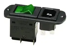
**Appliance Inlet Module X3130 for 2-pole circuit breaker 3130-FA.A**
## **Description**
The appliance inlet module X3130 with double pole circuit breaker 3130-FA.A combines three functions within a single component: A C14 appliance inlet and rocker switch with resettable overcurrent protection; screw mounting from the front or the rear.
## **Typical applications**
Electrical medical apparatus, laboratory equipment, professional audio equipment and office machines.
## **Ordering information**
**Type No. X3130** Appliance inlet module for circuit breaker type 3130-FA.A **Module A** appliance inlet C14 **Design 04** screw-type mounting **Accessories 00** without **Version 00** not wired; mounting position 3130: I to connector **01** not wired; mounting position 3130: 0 to connector (standard) **Delivery condition M** module supplied with circuit breaker FA.A
**X3130 - A 04 00 01 - M** Ordering example
## **Approvals**
ENEC, UL, CSA, CCC
## **Technical data**
||Rated voltage<br>Rated current|AC 240 V<br>10 A (IEC)<br>15 A(UL/CSA)|
|---|---|---|
||Ambient temperature|-25°C ... 70°C|
||Number of poles|L, N + ground|
||Cable cross section|max. 1.5 mm2|
||Degree ofprotection|Class I|
||Mounting method|screw-type mounting (front or rear)|
||Terminal design|blade terminals DIN 46244 A6.3 x 0.8|
||Housing material|thermoplastics, black UL94V-0|
||Appliance inlet<br>Switch|C14 accordingto IEC/EN 60320-1,UL 498<br>circuit breaker type 3130,2-pole|
## **Dimensions**
**==> picture [249 x 213] intentionally omitted <==**
**----- Start of picture text -----**<br>
Circuit breaker 3130 (2-pole)<br>ø 3.3 24<br>36.5 40.2<br>I.3<br>I.2<br>72 82 I.I LINE<br>**----- End of picture text -----**<br>
## **Mounting hole X3130**
**==> picture [249 x 225] intentionally omitted <==**
**----- Start of picture text -----**<br>
63.6 ± 0.15<br>2.50<br>72 ± 0.2<br>2.83<br>M3/Ø 3.3 Ø.130<br>1.24<br>31.6 ± 0.1<br>**----- End of picture text -----**<br>
**www.e-t-a.de**
1815
5
Updated at February 9, 2023
About Novapart
Novapart is a B2B electronic component broker specialising in stock shortages and cost reduction. We source hard-to-find parts and identify compliant alternatives across a catalogue of 410,000+ components from 500+ manufacturers.
Learn more →Stock Shortage Specialist
When a component is unavailable, discontinued or has an unacceptable lead time, we tap into our network of vetted European and Asian distributors to source what you need — without compromising on quality or traceability.
Request a quote →Compliant Alternatives
We identify pin-to-pin, electrically equivalent substitutes that meet the same certifications (RoHS, AEC-Q100, REACH) as your original specification — validated against datasheets, not just part numbers. Often at a lower cost.
BOM Analysis service →