
Image not available
Illustrative purposes only

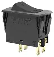
3120-N521-H7T1-W01D-20A
Thermal Circuit Breaker, On-Off, 3120-N Series, 20 A, 2 Pole, 50 V, 240 V, Snap In
⚠️ Reference pricing provided. In case of supply shortages, we will connect you with our trusted procurement partners to ensure your project's continuity.
- Manufacturer: ETA
- Product type: Thermal Circuit Breakers
- SVHC: No SVHC (17-Jan-2022)
- No. of Poles: 2 Pole
- Product Range: 3120-N Series
- Current Rating: 20A
- Voltage Rating VAC: 240V
- Voltage Rating VDC: 50V
- Circuit Breaker Mounting: Snap In
| Delivery and price | |
|---|---|
| Units per pack | 20 |
| Price | 35.03 € |
| Current stock | 10+ |
| Lead time | 30 days |
Datasheet

**3120-N...-...T1-... Thermal Circuit Breaker**

## **Description** Lo

The 3120-N...-...T1-... thermal circuit breaker/switch combination unites overcurrent protection and the function of an ON/OFF switch within a single component. The trip element is a thermobimetal. Type 3120-N...-...T1-... is ideally suited for overload protection of motors, pumps, transformers and cables. After tripping, it can reliably, easily and quickly be reset. The positively trip-free mechanism ensures reliable disconnection of the circuit even with the actuator blocked.

The 3120-N type is also available with thermal-magnetic trip. (technical data p. 21 ff.)

Type 3120-N is also available as a switch in accordance EN IEC 61058 (see data sheet switch 3120-N...Q1).

**==> picture [79 x 8] intentionally omitted <==**

**----- Start of picture text -----**<br>
3120-N...-...T1-...<br>**----- End of picture text -----**<br>


## **Typical applications** eee

Medical and laboratory equipment, apparatus and machine construction, professional tools, household and garden appliances, offices machines, audio equipment, machine tools

## **Your benefits**

   - l Maximum equipment availability is ensured by overload protection perfectly matched with the loads (prevention of nuisance tripping) and quick resettability

   - l Reduced mounting and wiring time

   - l Space saving design

- **Features** l Reduced disposition and storage costs

- Lo l Increased overall reliability l Single or double pole thermal circuit breaker/switch combination l Voltage ratings: AC 240 V, DC 50 V (AC 415 V upon request) l Current rating range: 0.1 … 20 A  (up to 30 A upon request) Po **Further information** l Optional: push-in terminals for easy and quick wiring with a longterm stability The current data sheet as well as other relevant documents are

The current data sheet as well as other relevant documents are available on our website: www.e-t-a.de/e016

- l Expandable functionality through appliance inlet module

- l Functional extension options with add-on modules for low voltage release, auxiliary contact function, remote trip or fast magnetic trip

- l Suitable for use in medical equipment according to IEC/EN 60601

## Lo **Approval logos**

## **Conformity** ee

**www.e-t-a.de**

2235

1

## **3120-N...-...T1-... Thermal Circuit Breaker**

## **Technical data**

|**For detailed technical information please see www.e-t-a.de/ti_e**|**For detailed technical information please see www.e-t-a.de/ti_e**|**For detailed technical information please see www.e-t-a.de/ti_e**|**For detailed technical information please see www.e-t-a.de/ti_e**|
|---|---|---|---|
|Rated voltage<br>AC 240 V, DC 50 V<br>(AC 415 V upon request)||||
|Current rating range<br>0.1 ... 20 A<br>(up to 30A upon request for 1-pole<br>devices only)||||
|**Typical life 1-pole (EN 60934)**<br>AC 240 V:<br>0.1 ... 20 A  30,000 cycles at 1 x IN, inductive<br>DC 50 V:<br>0.1 ... 4 A  30,000 cycles at 1 x IN, inductive<br>4.5 ... 16 A  30,000 cycles at 1 x IN, resistive<br>DC 28 V:<br>0.1 ... 20 A  30,000 cycles at 1 x IN,inductive||||
|**Typical life 2-pole (EN 60934)**<br>AC 240 V:<br>0.1 ... 16 A  50,000 cycles at 1 x IN, inductive<br>17 ... 20 A  30,000 cycles at 1 x IN, inductive<br>DC 50 V:<br>0.1 ... 16 A  50,000 cycles at 1 x IN, inductive<br>17 ... 20 A  10,000 cycles at 1 x IN,inductive||||
|Ambient temperature<br>-30 ... 60 °C||||
|Insulation coordination<br>(IEC 60664)<br>2.5 kV /2 reinforced insulation at<br>operatingarea||||
|**Dielectric strength**<br>Operating area<br>pole topole(2-pole)<br>Test voltage AC 3,000 V<br>Test voltage AC 1,500 V||||
|Insulation resistance<br>> 100 MΩ(DC 500 V)||||
|Rupture capacity Icn(IEC/EN 60934)||||
||IN|UN|Icn|
|1-pole, 2-pole|0.1 ... 2 A|AC 240 V /<br>DC 50 V|10 x IN|
|1-pole|2.5 ... 10 A|DC 50 V|50 A|
|1-pole|2.5 ... 20 A|AC 240 V /<br>DC 28 V|200 A|
|2-pole|2.5 ... 20 A|DC 50 V|250 A|
|2-pole|2.5 ... 20 A|AC 240 V /<br>DC 28 V|300 A|
|Interrupting capacity Inc (UL 1077)||||
||IN|UN|Inc|
|1-pole, 2-pole|0.1 ... 20 A|AC 250 V|5,000 A, C, 1|
|1-pole, 2-pole|0.1 ... 20 A|DC 50 V|1,000 A, C, 1|
|**Degree of protection (IEC 60529)**<br>Operating area<br>Terminal area<br>IP40<br>IP00<br>Other degrees of protection possible,<br>depending on selected variant,<br>see further details in data sheet.||||
|Vibration<br>8 g (57-500 Hz), ± 0.61 mm (10-57 Hz)<br>Test to IEC 60068-2-6, Test Fc<br>10 frequencycycles/axis||||
|Shock<br>30 g (11 ms)<br>Test to IEC 60068-2-27,Test Ea||||
|Corrosion<br>96 hours at 5 % salt mist,<br>Test to IEC 60068-2-11,Test Ka||||
|Humidity<br>240 hours in 95 % RH<br>Test to IEC 60068-2-78,<br>Test Cab||||
|Mass<br>approx. 27 g (1-pole)<br>approx. 31 g (2-pole)<br>approx. 42g (2-pole with PT terminals)||||


## **Current ratings and internal resistance values**

|**Current rating**<br>**(A)**|**Internal**<br>**resistance**<br>**per pole (Ω)**|**Current rating**<br>**(A)**|**Internal**<br>**resistance**<br>**per pole (Ω)**|
|---|---|---|---|
|0.1|94|4|0.0435|
|0.2|24|4.5|0.0435|
|0.3|12|5|0.0325|
|0.4|5.30|6|0.0215|
|0.5|4.20|7|0.0165|
|0.6|2.90|8|0.0165|
|0.8|1.50|10|< 0.02|
|1|0.9|12|< 0.02|
|1.2|0.80|14|< 0.02|
|1.5|0.45|15|< 0.02|
|2|0.27|16|< 0.02|
|2.5|0.0785|18|< 0.02|
|3|0.0595|20|< 0.02|
|3.5|0.0565|||


**www.e-t-a.de**

2

2235

**3120-N...-...T1-... Thermal Circuit Breaker**

## ~~oo~~ **Ordering information**

||**Mounting method**<br>**N3**Snap-in, mounting cut-out 50.5 x 21.5 mm<br>**N5**Snap-in, mounting cut-out 44.5 x 22 mm<br> **Number of poles**<br> **1**1-pole switching, 1-pole thermally protected<br> **2**2-pole switching, 2-pole thermally protected<br> **5**2-pole switching, 1-pole thermally protected<br> **Style**<br> **1**<br>Standard<br> **3**<br>With actuator guard<br> **4**<br>With accordion-style seal, IP65<br>**6**<br>Version with shorter flange<br>(only for mounting method N5)<br> **7**<br>With water splash cover (IP54 in the actuation<br>area) and shorter flange<br> **A**<br>With actuator guard and cross-hole (for optional<br>interlock)<br>**Terminal design**<br>**PT**Push-in terminals<br>**P7**Blade terminals<br>**H7**As P7, terminals 11 and 21 with flat head<br>screws M3.5 - standard for devices with<br>undervoltage release module<br>**N7**As P7, with additional shunt terminals 12(i)<br>and 22(i)<br>**G7**As N7, terminals 11 and 21 with additional flat<br>head screws M3.5<br>**Trip curve**<br>**T1**Thermal trip<br>**Actuator**<br>**W**Rocker<br> **Rocker colour and illumination**<br> **Opaque**<br> **01 .**<br>Black<br>without illumination<br> **02 .**<br>White<br>without illumination<br> **04 .**<br>Red<br>without illumination<br> **Translucent**(when named with Y/R/T/G<br>the rocker is illuminated)<br> **12 . (Y)**White<br>without illumination<br>(illuminated)<br> **14 . (R)**Red<br>without illumination<br>(illuminated)<br> **15 . (Y)**Orange  without illumination<br>(illuminated)<br> **16 . (T)**Blue<br>without illumination<br>(illuminated)<br> **19 . (G)**Green<br>without illumination<br>(illuminated)<br>**Marking of rocker**<br>**A**(not for style 4)<br>**D**<br>**F**<br>**K**<br>**L**<br>**X**<br>A<br>D<br>F<br>K<br>L<br>X|**Mounting method**<br>**N3**Snap-in, mounting cut-out 50.5 x 21.5 mm<br>**N5**Snap-in, mounting cut-out 44.5 x 22 mm<br> **Number of poles**<br> **1**1-pole switching, 1-pole thermally protected<br> **2**2-pole switching, 2-pole thermally protected<br> **5**2-pole switching, 1-pole thermally protected<br> **Style**<br> **1**<br>Standard<br> **3**<br>With actuator guard<br> **4**<br>With accordion-style seal, IP65<br>**6**<br>Version with shorter flange<br>(only for mounting method N5)<br> **7**<br>With water splash cover (IP54 in the actuation<br>area) and shorter flange<br> **A**<br>With actuator guard and cross-hole (for optional<br>interlock)<br>**Terminal design**<br>**PT**Push-in terminals<br>**P7**Blade terminals<br>**H7**As P7, terminals 11 and 21 with flat head<br>screws M3.5 - standard for devices with<br>undervoltage release module<br>**N7**As P7, with additional shunt terminals 12(i)<br>and 22(i)<br>**G7**As N7, terminals 11 and 21 with additional flat<br>head screws M3.5<br>**Trip curve**<br>**T1**Thermal trip<br>**Actuator**<br>**W**Rocker<br> **Rocker colour and illumination**<br> **Opaque**<br> **01 .**<br>Black<br>without illumination<br> **02 .**<br>White<br>without illumination<br> **04 .**<br>Red<br>without illumination<br> **Translucent**(when named with Y/R/T/G<br>the rocker is illuminated)<br> **12 . (Y)**White<br>without illumination<br>(illuminated)<br> **14 . (R)**Red<br>without illumination<br>(illuminated)<br> **15 . (Y)**Orange  without illumination<br>(illuminated)<br> **16 . (T)**Blue<br>without illumination<br>(illuminated)<br> **19 . (G)**Green<br>without illumination<br>(illuminated)<br>**Marking of rocker**<br>**A**(not for style 4)<br>**D**<br>**F**<br>**K**<br>**L**<br>**X**<br>A<br>D<br>F<br>K<br>L<br>X|**Mounting method**<br>**N3**Snap-in, mounting cut-out 50.5 x 21.5 mm<br>**N5**Snap-in, mounting cut-out 44.5 x 22 mm<br> **Number of poles**<br> **1**1-pole switching, 1-pole thermally protected<br> **2**2-pole switching, 2-pole thermally protected<br> **5**2-pole switching, 1-pole thermally protected<br> **Style**<br> **1**<br>Standard<br> **3**<br>With actuator guard<br> **4**<br>With accordion-style seal, IP65<br>**6**<br>Version with shorter flange<br>(only for mounting method N5)<br> **7**<br>With water splash cover (IP54 in the actuation<br>area) and shorter flange<br> **A**<br>With actuator guard and cross-hole (for optional<br>interlock)<br>**Terminal design**<br>**PT**Push-in terminals<br>**P7**Blade terminals<br>**H7**As P7, terminals 11 and 21 with flat head<br>screws M3.5 - standard for devices with<br>undervoltage release module<br>**N7**As P7, with additional shunt terminals 12(i)<br>and 22(i)<br>**G7**As N7, terminals 11 and 21 with additional flat<br>head screws M3.5<br>**Trip curve**<br>**T1**Thermal trip<br>**Actuator**<br>**W**Rocker<br> **Rocker colour and illumination**<br> **Opaque**<br> **01 .**<br>Black<br>without illumination<br> **02 .**<br>White<br>without illumination<br> **04 .**<br>Red<br>without illumination<br> **Translucent**(when named with Y/R/T/G<br>the rocker is illuminated)<br> **12 . (Y)**White<br>without illumination<br>(illuminated)<br> **14 . (R)**Red<br>without illumination<br>(illuminated)<br> **15 . (Y)**Orange  without illumination<br>(illuminated)<br> **16 . (T)**Blue<br>without illumination<br>(illuminated)<br> **19 . (G)**Green<br>without illumination<br>(illuminated)<br>**Marking of rocker**<br>**A**(not for style 4)<br>**D**<br>**F**<br>**K**<br>**L**<br>**X**<br>A<br>D<br>F<br>K<br>L<br>X|**Mounting method**<br>**N3**Snap-in, mounting cut-out 50.5 x 21.5 mm<br>**N5**Snap-in, mounting cut-out 44.5 x 22 mm<br> **Number of poles**<br> **1**1-pole switching, 1-pole thermally protected<br> **2**2-pole switching, 2-pole thermally protected<br> **5**2-pole switching, 1-pole thermally protected<br> **Style**<br> **1**<br>Standard<br> **3**<br>With actuator guard<br> **4**<br>With accordion-style seal, IP65<br>**6**<br>Version with shorter flange<br>(only for mounting method N5)<br> **7**<br>With water splash cover (IP54 in the actuation<br>area) and shorter flange<br> **A**<br>With actuator guard and cross-hole (for optional<br>interlock)<br>**Terminal design**<br>**PT**Push-in terminals<br>**P7**Blade terminals<br>**H7**As P7, terminals 11 and 21 with flat head<br>screws M3.5 - standard for devices with<br>undervoltage release module<br>**N7**As P7, with additional shunt terminals 12(i)<br>and 22(i)<br>**G7**As N7, terminals 11 and 21 with additional flat<br>head screws M3.5<br>**Trip curve**<br>**T1**Thermal trip<br>**Actuator**<br>**W**Rocker<br> **Rocker colour and illumination**<br> **Opaque**<br> **01 .**<br>Black<br>without illumination<br> **02 .**<br>White<br>without illumination<br> **04 .**<br>Red<br>without illumination<br> **Translucent**(when named with Y/R/T/G<br>the rocker is illuminated)<br> **12 . (Y)**White<br>without illumination<br>(illuminated)<br> **14 . (R)**Red<br>without illumination<br>(illuminated)<br> **15 . (Y)**Orange  without illumination<br>(illuminated)<br> **16 . (T)**Blue<br>without illumination<br>(illuminated)<br> **19 . (G)**Green<br>without illumination<br>(illuminated)<br>**Marking of rocker**<br>**A**(not for style 4)<br>**D**<br>**F**<br>**K**<br>**L**<br>**X**<br>A<br>D<br>F<br>K<br>L<br>X|**Mounting method**<br>**N3**Snap-in, mounting cut-out 50.5 x 21.5 mm<br>**N5**Snap-in, mounting cut-out 44.5 x 22 mm<br> **Number of poles**<br> **1**1-pole switching, 1-pole thermally protected<br> **2**2-pole switching, 2-pole thermally protected<br> **5**2-pole switching, 1-pole thermally protected<br> **Style**<br> **1**<br>Standard<br> **3**<br>With actuator guard<br> **4**<br>With accordion-style seal, IP65<br>**6**<br>Version with shorter flange<br>(only for mounting method N5)<br> **7**<br>With water splash cover (IP54 in the actuation<br>area) and shorter flange<br> **A**<br>With actuator guard and cross-hole (for optional<br>interlock)<br>**Terminal design**<br>**PT**Push-in terminals<br>**P7**Blade terminals<br>**H7**As P7, terminals 11 and 21 with flat head<br>screws M3.5 - standard for devices with<br>undervoltage release module<br>**N7**As P7, with additional shunt terminals 12(i)<br>and 22(i)<br>**G7**As N7, terminals 11 and 21 with additional flat<br>head screws M3.5<br>**Trip curve**<br>**T1**Thermal trip<br>**Actuator**<br>**W**Rocker<br> **Rocker colour and illumination**<br> **Opaque**<br> **01 .**<br>Black<br>without illumination<br> **02 .**<br>White<br>without illumination<br> **04 .**<br>Red<br>without illumination<br> **Translucent**(when named with Y/R/T/G<br>the rocker is illuminated)<br> **12 . (Y)**White<br>without illumination<br>(illuminated)<br> **14 . (R)**Red<br>without illumination<br>(illuminated)<br> **15 . (Y)**Orange  without illumination<br>(illuminated)<br> **16 . (T)**Blue<br>without illumination<br>(illuminated)<br> **19 . (G)**Green<br>without illumination<br>(illuminated)<br>**Marking of rocker**<br>**A**(not for style 4)<br>**D**<br>**F**<br>**K**<br>**L**<br>**X**<br>A<br>D<br>F<br>K<br>L<br>X|**Mounting method**<br>**N3**Snap-in, mounting cut-out 50.5 x 21.5 mm<br>**N5**Snap-in, mounting cut-out 44.5 x 22 mm<br> **Number of poles**<br> **1**1-pole switching, 1-pole thermally protected<br> **2**2-pole switching, 2-pole thermally protected<br> **5**2-pole switching, 1-pole thermally protected<br> **Style**<br> **1**<br>Standard<br> **3**<br>With actuator guard<br> **4**<br>With accordion-style seal, IP65<br>**6**<br>Version with shorter flange<br>(only for mounting method N5)<br> **7**<br>With water splash cover (IP54 in the actuation<br>area) and shorter flange<br> **A**<br>With actuator guard and cross-hole (for optional<br>interlock)<br>**Terminal design**<br>**PT**Push-in terminals<br>**P7**Blade terminals<br>**H7**As P7, terminals 11 and 21 with flat head<br>screws M3.5 - standard for devices with<br>undervoltage release module<br>**N7**As P7, with additional shunt terminals 12(i)<br>and 22(i)<br>**G7**As N7, terminals 11 and 21 with additional flat<br>head screws M3.5<br>**Trip curve**<br>**T1**Thermal trip<br>**Actuator**<br>**W**Rocker<br> **Rocker colour and illumination**<br> **Opaque**<br> **01 .**<br>Black<br>without illumination<br> **02 .**<br>White<br>without illumination<br> **04 .**<br>Red<br>without illumination<br> **Translucent**(when named with Y/R/T/G<br>the rocker is illuminated)<br> **12 . (Y)**White<br>without illumination<br>(illuminated)<br> **14 . (R)**Red<br>without illumination<br>(illuminated)<br> **15 . (Y)**Orange  without illumination<br>(illuminated)<br> **16 . (T)**Blue<br>without illumination<br>(illuminated)<br> **19 . (G)**Green<br>without illumination<br>(illuminated)<br>**Marking of rocker**<br>**A**(not for style 4)<br>**D**<br>**F**<br>**K**<br>**L**<br>**X**<br>A<br>D<br>F<br>K<br>L<br>X|**Mounting method**<br>**N3**Snap-in, mounting cut-out 50.5 x 21.5 mm<br>**N5**Snap-in, mounting cut-out 44.5 x 22 mm<br> **Number of poles**<br> **1**1-pole switching, 1-pole thermally protected<br> **2**2-pole switching, 2-pole thermally protected<br> **5**2-pole switching, 1-pole thermally protected<br> **Style**<br> **1**<br>Standard<br> **3**<br>With actuator guard<br> **4**<br>With accordion-style seal, IP65<br>**6**<br>Version with shorter flange<br>(only for mounting method N5)<br> **7**<br>With water splash cover (IP54 in the actuation<br>area) and shorter flange<br> **A**<br>With actuator guard and cross-hole (for optional<br>interlock)<br>**Terminal design**<br>**PT**Push-in terminals<br>**P7**Blade terminals<br>**H7**As P7, terminals 11 and 21 with flat head<br>screws M3.5 - standard for devices with<br>undervoltage release module<br>**N7**As P7, with additional shunt terminals 12(i)<br>and 22(i)<br>**G7**As N7, terminals 11 and 21 with additional flat<br>head screws M3.5<br>**Trip curve**<br>**T1**Thermal trip<br>**Actuator**<br>**W**Rocker<br> **Rocker colour and illumination**<br> **Opaque**<br> **01 .**<br>Black<br>without illumination<br> **02 .**<br>White<br>without illumination<br> **04 .**<br>Red<br>without illumination<br> **Translucent**(when named with Y/R/T/G<br>the rocker is illuminated)<br> **12 . (Y)**White<br>without illumination<br>(illuminated)<br> **14 . (R)**Red<br>without illumination<br>(illuminated)<br> **15 . (Y)**Orange  without illumination<br>(illuminated)<br> **16 . (T)**Blue<br>without illumination<br>(illuminated)<br> **19 . (G)**Green<br>without illumination<br>(illuminated)<br>**Marking of rocker**<br>**A**(not for style 4)<br>**D**<br>**F**<br>**K**<br>**L**<br>**X**<br>A<br>D<br>F<br>K<br>L<br>X|**Mounting method**<br>**N3**Snap-in, mounting cut-out 50.5 x 21.5 mm<br>**N5**Snap-in, mounting cut-out 44.5 x 22 mm<br> **Number of poles**<br> **1**1-pole switching, 1-pole thermally protected<br> **2**2-pole switching, 2-pole thermally protected<br> **5**2-pole switching, 1-pole thermally protected<br> **Style**<br> **1**<br>Standard<br> **3**<br>With actuator guard<br> **4**<br>With accordion-style seal, IP65<br>**6**<br>Version with shorter flange<br>(only for mounting method N5)<br> **7**<br>With water splash cover (IP54 in the actuation<br>area) and shorter flange<br> **A**<br>With actuator guard and cross-hole (for optional<br>interlock)<br>**Terminal design**<br>**PT**Push-in terminals<br>**P7**Blade terminals<br>**H7**As P7, terminals 11 and 21 with flat head<br>screws M3.5 - standard for devices with<br>undervoltage release module<br>**N7**As P7, with additional shunt terminals 12(i)<br>and 22(i)<br>**G7**As N7, terminals 11 and 21 with additional flat<br>head screws M3.5<br>**Trip curve**<br>**T1**Thermal trip<br>**Actuator**<br>**W**Rocker<br> **Rocker colour and illumination**<br> **Opaque**<br> **01 .**<br>Black<br>without illumination<br> **02 .**<br>White<br>without illumination<br> **04 .**<br>Red<br>without illumination<br> **Translucent**(when named with Y/R/T/G<br>the rocker is illuminated)<br> **12 . (Y)**White<br>without illumination<br>(illuminated)<br> **14 . (R)**Red<br>without illumination<br>(illuminated)<br> **15 . (Y)**Orange  without illumination<br>(illuminated)<br> **16 . (T)**Blue<br>without illumination<br>(illuminated)<br> **19 . (G)**Green<br>without illumination<br>(illuminated)<br>**Marking of rocker**<br>**A**(not for style 4)<br>**D**<br>**F**<br>**K**<br>**L**<br>**X**<br>A<br>D<br>F<br>K<br>L<br>X|**Mounting method**<br>**N3**Snap-in, mounting cut-out 50.5 x 21.5 mm<br>**N5**Snap-in, mounting cut-out 44.5 x 22 mm<br> **Number of poles**<br> **1**1-pole switching, 1-pole thermally protected<br> **2**2-pole switching, 2-pole thermally protected<br> **5**2-pole switching, 1-pole thermally protected<br> **Style**<br> **1**<br>Standard<br> **3**<br>With actuator guard<br> **4**<br>With accordion-style seal, IP65<br>**6**<br>Version with shorter flange<br>(only for mounting method N5)<br> **7**<br>With water splash cover (IP54 in the actuation<br>area) and shorter flange<br> **A**<br>With actuator guard and cross-hole (for optional<br>interlock)<br>**Terminal design**<br>**PT**Push-in terminals<br>**P7**Blade terminals<br>**H7**As P7, terminals 11 and 21 with flat head<br>screws M3.5 - standard for devices with<br>undervoltage release module<br>**N7**As P7, with additional shunt terminals 12(i)<br>and 22(i)<br>**G7**As N7, terminals 11 and 21 with additional flat<br>head screws M3.5<br>**Trip curve**<br>**T1**Thermal trip<br>**Actuator**<br>**W**Rocker<br> **Rocker colour and illumination**<br> **Opaque**<br> **01 .**<br>Black<br>without illumination<br> **02 .**<br>White<br>without illumination<br> **04 .**<br>Red<br>without illumination<br> **Translucent**(when named with Y/R/T/G<br>the rocker is illuminated)<br> **12 . (Y)**White<br>without illumination<br>(illuminated)<br> **14 . (R)**Red<br>without illumination<br>(illuminated)<br> **15 . (Y)**Orange  without illumination<br>(illuminated)<br> **16 . (T)**Blue<br>without illumination<br>(illuminated)<br> **19 . (G)**Green<br>without illumination<br>(illuminated)<br>**Marking of rocker**<br>**A**(not for style 4)<br>**D**<br>**F**<br>**K**<br>**L**<br>**X**<br>A<br>D<br>F<br>K<br>L<br>X|
|---|---|---|---|---|---|---|---|---|---|
|||**Number of poles**<br> **1**1-pole switching, 1-pole thermally protected<br> **2**2-pole switching, 2-pole thermally protected<br> **5**2-pole switching, 1-pole thermally protected<br> **Style**<br> **1**<br>Standard<br> **3**<br>With actuator guard<br> **4**<br>With accordion-style seal, IP65<br>**6**<br>Version with shorter flange<br>(only for mounting method N5)<br> **7**<br>With water splash cover (IP54 in the actuation<br>area) and shorter flange<br> **A**<br>With actuator guard and cross-hole (for optional<br>interlock)<br>**Terminal design**<br>**PT**Push-in terminals<br>**P7**Blade terminals<br>**H7**As P7, terminals 11 and 21 with flat head<br>screws M3.5 - standard for devices with<br>undervoltage release module<br>**N7**As P7, with additional shunt terminals 12(i)<br>and 22(i)<br>**G7**As N7, terminals 11 and 21 with additional flat<br>head screws M3.5<br>**Trip curve**<br>**T1**Thermal trip<br>**Actuator**<br>**W**Rocker<br> **Rocker colour and illumination**<br> **Opaque**<br> **01 .**<br>Black<br>without illumination<br> **02 .**<br>White<br>without illumination<br> **04 .**<br>Red<br>without illumination<br> **Translucent**(when named with Y/R/T/G<br>the rocker is illuminated)<br> **12 . (Y)**White<br>without illumination<br>(illuminated)<br> **14 . (R)**Red<br>without illumination<br>(illuminated)<br> **15 . (Y)**Orange  without illumination<br>(illuminated)<br> **16 . (T)**Blue<br>without illumination<br>(illuminated)<br> **19 . (G)**Green<br>without illumination<br>(illuminated)<br>**Marking of rocker**<br>**A**(not for style 4)<br>**D**<br>**F**<br>**K**<br>**L**<br>**X**<br>A<br>D<br>F<br>K<br>L<br>X||||||||
||||**Style**<br> **1**<br>Standard<br> **3**<br>With actuator guard<br> **4**<br>With accordion-style seal, IP65<br>**6**<br>Version with shorter flange<br>(only for mounting method N5)<br> **7**<br>With water splash cover (IP54 in the actuation<br>area) and shorter flange<br> **A**<br>With actuator guard and cross-hole (for optional<br>interlock)<br>**Terminal design**<br>**PT**Push-in terminals<br>**P7**Blade terminals<br>**H7**As P7, terminals 11 and 21 with flat head<br>screws M3.5 - standard for devices with<br>undervoltage release module<br>**N7**As P7, with additional shunt terminals 12(i)<br>and 22(i)<br>**G7**As N7, terminals 11 and 21 with additional flat<br>head screws M3.5<br>**Trip curve**<br>**T1**Thermal trip<br>**Actuator**<br>**W**Rocker<br> **Rocker colour and illumination**<br> **Opaque**<br> **01 .**<br>Black<br>without illumination<br> **02 .**<br>White<br>without illumination<br> **04 .**<br>Red<br>without illumination<br> **Translucent**(when named with Y/R/T/G<br>the rocker is illuminated)<br> **12 . (Y)**White<br>without illumination<br>(illuminated)<br> **14 . (R)**Red<br>without illumination<br>(illuminated)<br> **15 . (Y)**Orange  without illumination<br>(illuminated)<br> **16 . (T)**Blue<br>without illumination<br>(illuminated)<br> **19 . (G)**Green<br>without illumination<br>(illuminated)<br>**Marking of rocker**<br>**A**(not for style 4)<br>**D**<br>**F**<br>**K**<br>**L**<br>**X**<br>A<br>D<br>F<br>K<br>L<br>X|||||||
|||||**Terminal design**<br>**PT**Push-in terminals<br>**P7**Blade terminals<br>**H7**As P7, terminals 11 and 21 with flat head<br>screws M3.5 - standard for devices with<br>undervoltage release module<br>**N7**As P7, with additional shunt terminals 12(i)<br>and 22(i)<br>**G7**As N7, terminals 11 and 21 with additional flat<br>head screws M3.5<br>**Trip curve**<br>**T1**Thermal trip<br>**Actuator**<br>**W**Rocker<br> **Rocker colour and illumination**<br> **Opaque**<br> **01 .**<br>Black<br>without illumination<br> **02 .**<br>White<br>without illumination<br> **04 .**<br>Red<br>without illumination<br> **Translucent**(when named with Y/R/T/G<br>the rocker is illuminated)<br> **12 . (Y)**White<br>without illumination<br>(illuminated)<br> **14 . (R)**Red<br>without illumination<br>(illuminated)<br> **15 . (Y)**Orange  without illumination<br>(illuminated)<br> **16 . (T)**Blue<br>without illumination<br>(illuminated)<br> **19 . (G)**Green<br>without illumination<br>(illuminated)<br>**Marking of rocker**<br>**A**(not for style 4)<br>**D**<br>**F**<br>**K**<br>**L**<br>**X**<br>A<br>D<br>F<br>K<br>L<br>X||||||
||||||**Trip curve**<br>**T1**Thermal trip<br>**Actuator**<br>**W**Rocker<br> **Rocker colour and illumination**<br> **Opaque**<br> **01 .**<br>Black<br>without illumination<br> **02 .**<br>White<br>without illumination<br> **04 .**<br>Red<br>without illumination<br> **Translucent**(when named with Y/R/T/G<br>the rocker is illuminated)<br> **12 . (Y)**White<br>without illumination<br>(illuminated)<br> **14 . (R)**Red<br>without illumination<br>(illuminated)<br> **15 . (Y)**Orange  without illumination<br>(illuminated)<br> **16 . (T)**Blue<br>without illumination<br>(illuminated)<br> **19 . (G)**Green<br>without illumination<br>(illuminated)<br>**Marking of rocker**<br>**A**(not for style 4)<br>**D**<br>**F**<br>**K**<br>**L**<br>**X**<br>A<br>D<br>F<br>K<br>L<br>X|||||
|||||||**Actuator**<br>**W**Rocker<br> **Rocker colour and illumination**<br> **Opaque**<br> **01 .**<br>Black<br>without illumination<br> **02 .**<br>White<br>without illumination<br> **04 .**<br>Red<br>without illumination<br> **Translucent**(when named with Y/R/T/G<br>the rocker is illuminated)<br> **12 . (Y)**White<br>without illumination<br>(illuminated)<br> **14 . (R)**Red<br>without illumination<br>(illuminated)<br> **15 . (Y)**Orange  without illumination<br>(illuminated)<br> **16 . (T)**Blue<br>without illumination<br>(illuminated)<br> **19 . (G)**Green<br>without illumination<br>(illuminated)<br>**Marking of rocker**<br>**A**(not for style 4)<br>**D**<br>**F**<br>**K**<br>**L**<br>**X**<br>A<br>D<br>F<br>K<br>L<br>X||||
||||||||**Rocker colour and illumination**<br>**Opaque**<br>**01 .**<br>Black<br>without illumination<br>**02 .**<br>White<br>without illumination<br>**04 .**<br>Red<br>without illumination<br> **Translucent**(when named with Y/R/T/G<br>the rocker is illuminated)<br>**12 . (Y)**White<br>without illumination<br>(illuminated)<br>**14 . (R)**Red<br>without illumination<br>(illuminated)<br>**15 . (Y)**Orange  without illumination<br>(illuminated)<br>**16 . (T)**Blue<br>without illumination<br>(illuminated)<br>**19 . (G)**Green<br>without illumination<br>(illuminated)<br>**Marking of rocker**<br>**A**(not for style 4)<br>**D**<br>**F**<br>**K**<br>**L**<br>**X**<br>A<br>D<br>F<br>K<br>L<br>X|||
|||||||||**Marking of rocker**<br>**A**(not for style 4)<br>**D**<br>**F**<br>**K**<br>**L**<br>**X**<br>A<br>D<br>F<br>K<br>L<br>X||
|||||||||||


|**3120-N5  2  4**|**N5  2  4**|**N5  2  4**|**N5  2  4- PT  T1**|**PT  T1-W 19 D G ...**|**W 19 D G ...**|**W 19 D G ...**|**W 19 D G ...**<br>Ordering example<br>**Illumination voltage**|**W 19 D G ...**<br>Ordering example<br>**Illumination voltage**|**W 19 D G ...**<br>Ordering example<br>**Illumination voltage**|
|---|---|---|---|---|---|---|---|---|---|
||||||||(|(|(=operating voltage)|
||||||||**1**DC 12 V||DC 12 V|
||||||||**2**DC 24 V||DC 24 V|
||||||||**3**AC 115 V||AC 115 V|
||||||||**4**AC 230 V||AC 230 V|
||||||||**5**DC 48 V||DC 48 V|
||||||||**6**AC 400 V (for 2-pole versions||AC 400 V (for 2-pole versions|
||||||||||up to 16 A)|
||||||||||**Current rating**|
||||||||||**0.1 ... 20 A**|
||||||||||**Terminal shroud**|
||||||||||**(optional)**|
||||||||||**A**With terminal|
||||||||||shroud, mounted*|
|||||||||||
|**3120-N5  2  4**|**N5  2  4**|**N5  2  4**|**N5  2  4- PT  T1**|**PT  T1-W 19 D G 4**|**W 19 D G 4**|**W 19 D G 4**|**W 19 D G 4- 16 A- (A)**Ordering-example|||


- Optional. If -A is added to the order designation, the 3120 is supplied with the mounted terminal shroud. Only available in combination with -P7 or -N7 terminal design variants.

**3120-N5  2  4 - PT  T1-W 19 D G ...** Ordering example

**www.e-t-a.de**

2235

3

**3120-N...-...T1-... Thermal Circuit Breaker**

|**1**<br>**Ordering information**<br>**Type no.**<br>**3120**Thermal circuit breaker/switch combination with push button<br>actuation<br>**Mounting method**<br>~~————~~|**1**<br>**Ordering information**<br>**Type no.**<br>**3120**Thermal circuit breaker/switch combination with push button<br>actuation<br>**Mounting method**<br>~~————~~|**1**<br>**Ordering information**<br>**Type no.**<br>**3120**Thermal circuit breaker/switch combination with push button<br>actuation<br>**Mounting method**<br>~~————~~|**1**<br>**Ordering information**<br>**Type no.**<br>**3120**Thermal circuit breaker/switch combination with push button<br>actuation<br>**Mounting method**<br>~~————~~|**1**<br>**Ordering information**<br>**Type no.**<br>**3120**Thermal circuit breaker/switch combination with push button<br>actuation<br>**Mounting method**<br>~~————~~|**1**<br>**Ordering information**<br>**Type no.**<br>**3120**Thermal circuit breaker/switch combination with push button<br>actuation<br>**Mounting method**<br>~~————~~|**1**<br>**Ordering information**<br>**Type no.**<br>**3120**Thermal circuit breaker/switch combination with push button<br>actuation<br>**Mounting method**<br>~~————~~|**1**<br>**Ordering information**<br>**Type no.**<br>**3120**Thermal circuit breaker/switch combination with push button<br>actuation<br>**Mounting method**<br>~~————~~|**1**<br>**Ordering information**<br>**Type no.**<br>**3120**Thermal circuit breaker/switch combination with push button<br>actuation<br>**Mounting method**<br>~~————~~|**Ordering information**<br>**Type no.**<br>**3120**Thermal resettable circuit breaker with push button<br>**Mounting method**<br>**N3**Snap-in, mounting cut-out 50.5 x 21.5 mm|**Ordering information**<br>**Type no.**<br>**3120**Thermal resettable circuit breaker with push button<br>**Mounting method**<br>**N3**Snap-in, mounting cut-out 50.5 x 21.5 mm|**Ordering information**<br>**Type no.**<br>**3120**Thermal resettable circuit breaker with push button<br>**Mounting method**<br>**N3**Snap-in, mounting cut-out 50.5 x 21.5 mm|**Ordering information**<br>**Type no.**<br>**3120**Thermal resettable circuit breaker with push button<br>**Mounting method**<br>**N3**Snap-in, mounting cut-out 50.5 x 21.5 mm|
|---|---|---|---|---|---|---|---|---|---|---|---|---|
|||**N3**Snap-in, mounting cut-out 50.5 x 21.5 mm||||||||**N5**Snap-in, mounting cut-out 44.5 x 22 mm|||
|||**N5**Snap-in, mounting cut-out 44.5 x 22 mm|||||||||**Number of poles**||
||||**Number of poles**||||||||**1**1-pole thermally protected||
||||**1**1-pole switching, 1|||||pole switching, 1-pole thermally protected|||**2**2-pole thermally protected||
||||**2**2-pole switching, 2|||||pole switching, 2-pole thermally protected|||**5**2-pole, 1-pole thermally protected||
||||**5**2-pole switching, 1|||||pole switching, 1-pole thermally protected||||**Style**|
|||||**Style**||||||||**G**Resettable circuit breaker|
|||||**D**With actuator guard||With actuator guard||||||**Terminal design**|
|||||**E**||With actuator guard and water splash cover IP54||||||**PT**Push-in terminals|
|||||**F**||With power-on protection||||||**P7**Blade terminals|
|||||**V**||With power-on protection and water splash cover||||||**H7**As P7, terminals 11 and 21 with flat head|
|||||||IP54||||||screws M3.5 - standard for units with|
|||||||**Terminal design**||||||undervoltage release module|
|||||||**PT**Push||Push-in terminals||||**N7**As P7, with additional shunt terminals 12(i)|
|||||||**P7**Blade terminals||Blade terminals||||and 22(i)|
|||||||**H7**As P7, terminals 11 and 21 with flat head||As P7, terminals 11 and 21 with flat head||||**G7**As N7, terminals 11 and 21 with additional flat|
|||||||||screws M3.5 - standard for units with||||head screws M3.5|
|||||||||undervoltage release module||||**Trip curve**|
|||||||**N7**As P7, with additional shunt terminals 12(i)||As P7, with additional shunt terminals 12(i)||||**T1**Thermal trip|
|||||||||and 22(i)||||**Actuator**|
|||||||**G7**As N7, terminals 11 and 21 with additional flat||As N7, terminals 11 and 21 with additional flat||||**D**One push button|
|||||||||head screws M3.5||||**Colour of push button**|
|||||||||**Trip curve**||||**01**Black|
|||||||||**T1**Thermal trip||||**02**White opaque|
|||||||||**Actuator**||||**04**Red opaque (UL/CSA approval only)|
|||||||||**S**Two push buttons||||**09**Green opaque|
|||||||||**Colour of push button/illumination**||||<br>**Marking of the push button**|
|||||||||**(Style D and F without water splash**||||**X**Without marking|
|||||||||**protection)**||||**Current rating**|
|||||||||**GRD**<br>Green/red without illumination||||**0.1 ... 20 A**|
|||||||||**GRDG**<br>Green with LED illumination/red|Green with LED illumination/red|||**Terminal shroud**|
|||||||||without illumination||||**(optional)**|
|||||||||**Colour of push button/illumination**||||**A**With terminal shroud,|
|||||||||**(Style E and V with water splash**||||mounted*|
|||||||||**protection)**|||||
|||||||||**GRX**<br>Green/red without illumination|**3120-N3  2  G- PT T1- D 01- X   20 A- (A)**Ordering-example||||
|||||||||**GRXG**<br>Green with LED illumination/red|Green with LED illumination/red||||
|||||||||without illumination|Please observe our minimum ordering quantities.||||
|||||||||**Illumination voltage range**|||||
|||||||||(=operating voltage)|*  Optional. If -A is added to the order designation, the 3120 is||||
|||||||||**1**DC 12 V|supplied with the mounted terminal shroud. Only available in||||
|||||||||**2**DC 24 V|combination with -P7 or -N7 terminal design variants.||||
|||||||||**3**AC 115 V|||||
|||||||||**4**AC 230 V<br>**5**DC 48 V<br>**6**AC 400 V (for 2-pole versions up<br>~~CO ~~|**Customer-specific solutions**<br> OO||||
|||||||||to 16 A)|Looking for a version you cannot find in our order numbering code?|||Looking for a version you cannot find in our order numbering code?|
|||||||||**Current rating**|Please get in touch.||||
|||||||||**0.1 ... 20 A**|||||
|||||||||**Terminal shroud**|||||
|||||||||**(optional)**|||||
|||||||||**A**With terminal shroud,|||||
|||||||||mounted*|||||


**Customer-specific solutions** OO Looking for a version you cannot find in our order numbering code? Please get in touch.

**3120-N3  5  V - PT  T1-S GRD    - 20 A - (A)** Ordering - example

4 **www.e-t-a.de** 2235 ~~SCs~~

## **3120-N...-...T1-... Thermal Circuit Breaker**

## **Approvals**

## **Time/current characteristics**

|**Approval**<br>**authority**<br>**Standard**|**Standard **|**Rated**<br>**voltage**|**Current rating range**|**Appr.-**<br>**marks**|
|---|---|---|---|---|
|VDE<br>IEC/EN<br>60934|IEC/EN<br>60934|AC 240 V<br>DC 50 V<br>DC 50 V<br>DC 28 V|0.1 A ... 20 A<br>0.1 ... 20 A (2-pole)<br>0.1 ... 16 A (1-pole)<br>0.1 A ... 20 A|—|
|UL<br>UL 1077|UL 1077|AC 250 V<br>AC 250 V<br>DC 50 V<br>AC 250 V|0.1 A ... 16 A (TC1, OL1)<br>17 A … 20 A (TC1, OL0)<br>0.1 A … 20 A (TC1, OL0)<br>30 A*<br>(TC1,OL0)|0.1 A ... 16 A (TC1, OL1)<br>17 A … 20 A (TC1, OL0)<br>0.1 A … 20 A (TC1, OL0)|
|CSA<br>C22.2<br>No 235|C22.2<br>No 235|AC 250 V<br>AC 250 V<br>DC 50 V<br>AC 250 V|0.1 A ... 16 A (TC1, OL1)<br>17 A … 20 A (TC1, OL0)<br>0.1 A … 20 A (TC1, OL0)<br>30 A*<br>(TC1,OL0)|0.1 A ... 16 A (TC1, OL1)<br>17 A … 20 A (TC1, OL0)<br>0.1 A … 20 A (TC1, OL0)|
|CQC<br>GB<br>17701|GB<br>17701|AC 240 V<br>DC 50 V|0.1 A … 20 A<br>0.1 A … 20 A||
|KTL<br>KC60934|KC60934|AC 240 V|0.1 ... 20 A (2-pole)||


* 2 poles in parallel

## **Mounting method**

**==> picture [247 x 201] intentionally omitted <==**

**----- Start of picture text -----**<br>
Mounting method<br>mounting cut-out -N3 mounting cut-out -N5<br>-0.2 -0.2<br>-0.4 -0.4<br>-0.007 -0.007<br>L -0.01 -0.015<br>±0.05 +1 ±0.05 +1<br>±0.001min. 55+0.039 ±0.001min. 49+0,039<br>min. 2.165 min. 1.929<br>+0.5+0.019 +0.5+0.019<br>ee ey<br>50.5 [+0.3] 44.5 [+0.2]<br>___ 1.988 [+0.011] _ -_ 1.751 [+0,007] _<br>Panel thickness Style variants  Style variants<br>1/3/6/7/A/D/F/G 4, E and V<br>a 1 – 6.35 mm 1 – 5.5 mm<br>— ————<br>b 1 – 4 mm 1 – 3.2 mm<br>a<br>a b<br>+0.3 +0.011 +0.3 +0.011<br>22<br>21.5 0.846 0.866<br>**----- End of picture text -----**<br>


## **Schematic diagrams**

**==> picture [222 x 160] intentionally omitted <==**

**----- Start of picture text -----**<br>
2-pole switching and  2-pole switching and<br>2-pole thermally protected 1-pole thermally protected<br>11 line 21 11 line 21<br>12(i) 22(i) 12(i) 22(i)<br>| [i 12(k) load 22(k) | fl 12(k) load<br>1-pole switching and<br>1-pole thermally protected<br>line<br>11 i<br>12(i) 22(i)<br>12(k) load<br>**----- End of picture text -----**<br>


**==> picture [224 x 457] intentionally omitted <==**

**----- Start of picture text -----**<br>
0.1…2 A<br>10000   60 °C<br>  23 °C<br>1 eeee -30 °C<br>1000<br>Hep<br>100<br>A<br>10<br>1<br>0.1 eine<br>1 1.4 2 4 6 8 10 20 40<br>Multiple of rated current<br>2.5…20 A<br>10000   60 °C<br>  23 °C<br>-30 °C<br>1000 er<br>icclin<br>100<br>10<br>ONS<br>a Nie<br>1<br>a<br>0.1<br>HT 1 1.4 2 4 6 8 10 20 40<br>Multiple of rated current<br>Time in seconds<br>Time in seconds<br>**----- End of picture text -----**<br>


The time/current characteristic depends on the ambient temperature. In order to eliminate nuisance or late tripping, please multiply the current rating of the circuit breaker by a temperature factor (see chapter Technical Information) For detailed technical information please see www.e-t-a.de/ti_e

Ambient -30 -20 -10 0 23 40 50 60 temperature [°C] Temperature factor 0.8 0.84 0.88 0.92 1 1.08 1.14 1.23 ~~||~~ titi tlt

**www.e-t-a.de**

2235

5

**3120-N...-...T1-... Thermal Circuit Breaker**

## **Dimensions**

**==> picture [512 x 535] intentionally omitted <==**

**----- Start of picture text -----**<br>
3120-N3.1-H7... 3120-N5.1-P7...<br>25 OFF position 25<br>0.984 0.984<br>15.5 56.4 15.5 52.4<br>0.610 2.220 0.610 2.063<br>10.7 15.5 3 10.7 15.5 3<br>0.421 0.610 0.118 0.421 0.610 0.118<br>21 41 21 41<br>1.61 0.827 1.61<br>0.827<br>blade terminal  blade terminal<br>6.3 x 0.8 6.3 x 0.8<br>flat head screw M3.5x6<br>tightening torque<br>max. 0.8 Nm<br>3120-N5.6-P7... 3120-N5.7-P7...<br>50<br>25 27 1.97<br>0.984 48 1.0619.5 34.9<br>15.5 1.89 0.77 1.37<br>0.610<br>10.7 15.5 3 10.7 15.5 3<br>0.421 0.610 41 0.118 0.421 0.610 41 0.118<br>21 1.61 21 1.61<br>0.827 0.827<br>blade terminal  blade terminal<br>6.3 x 0.8 6.3 x 0.8<br>9.6 0.377 9.6 0.377<br>33 1.30 33 1.30<br>10 0.394 10 0.394<br>9.6 0.377<br>14.8 0.58<br>33 1.30 33 1.30<br>10 10<br>0.394 0.394<br>**----- End of picture text -----**<br>


**www.e-t-a.de**

6

2235

**3120-N...-...T1-... Thermal Circuit Breaker**

## **Dimensions**

**==> picture [465 x 445] intentionally omitted <==**

**----- Start of picture text -----**<br>
3120-N5.1-PT... 3120-N5.3-P7...<br>25 25<br>0.98<br>0.984 15.5 52.4<br>15.5 12.65  12.65  5.5 0.610 2.06<br>0.610 0.498  0.498  0.216<br>10.7 15.5 3<br>0.421 0.610 0.118<br>21 42.5 21 41<br>0.827 1.67  0.827 1.61<br>blade terminal<br>6.3 x 0.8<br>3120-N5.4-P7... 3120-N5.A-P7...<br>28 54 25 52.4<br>1.102 2.12 0.984 2.063<br>15.5 10<br>0.610 0.394<br>0.42110.7 0.61015.5 0.1183 0.42110.7 0.61015.5 0.1183<br>21 blade terminal  41 21 blade terminal  41<br>0.827 6.3 x 0.8 1.61 0.827 6.3 x 0.8 1.61<br>25 0.98<br>9.6 0.377<br>9.6 0.377<br>33 1.30<br>48 1.89<br>10<br>0.394<br>9.6 0.370 5.5 0.216<br>16 0.629<br>32.3 1.271 33 1.30<br>10 0.394 10 0.394<br>**----- End of picture text -----**<br>


**www.e-t-a.de**

2235

7

**3120-N...-...T1-... Thermal Circuit Breaker**

## **Dimensions**

**==> picture [512 x 692] intentionally omitted <==**

**----- Start of picture text -----**<br>
3120-N3.D-P7... 3120-N5.D-P7... ON position<br>26.4 52.4<br>1.039 2.063<br>10.7 15.5 3 10.7 15.5 3<br>0.421 0.610 0.118 0.421 0.610 0.118<br>0.82721 blade terminal 6.3 x 0.8 1.6141 0.82721 blade terminal 6.3 x 0.8 1.6141<br>21.9<br>56.4 0.862<br>2.22<br>3120-N5.E-P7... 3120-N5.F-P7...<br>ON position<br>26.4 52.4<br>29.2  55 1.039 2.063<br>1.149 2.165<br>10.7 15.5 3<br>15.5 3 0.421 0.610 0.118<br>10.7 0.610 0.118 21 41<br>0.421 0.827 1.61<br>21 blade terminal  41 blade terminal<br>0.827 6.3 x 0.8 1.61 6.3 x 0.8<br>3120-N5.V-P7...<br>29.2  55<br>1.149 2.165<br>15.5 3<br>10.7 0.610 0.118<br>0.421<br>21 blade terminal  41<br>0.827 6.3 x 0.8 1.61<br>9.1 0.358 9.1 0.358<br>33 1.30 33 1.30<br>10 10<br>0.394 0.394<br>21.7 0.854 26.4 1.039<br>5  0.196 5  0.196<br>9.1 0.358<br>17 0.669<br>33 1.30<br>32.3 1.271<br>10<br>0.394<br>10<br>0.394<br>17 0.669<br>32.3 1.271<br>10<br>0.394<br>**----- End of picture text -----**<br>


**www.e-t-a.de**

8

2235

**3120-N...-...T1-... Thermal Circuit Breaker**

## **Dimensions**

**==> picture [219 x 476] intentionally omitted <==**

**----- Start of picture text -----**<br>
3120-N3.G-P7...<br>OFF position<br>26.4<br>56.4<br>1.039<br>2.220<br>21.7 21.9<br>0.854 0.862<br>15.5 3<br>10.7 0.610 0.118<br>0.421 blade terminals<br>21 6.3 x 0.8 41<br>0.827 1.61<br>3120-N5.G-P7...<br>26.4 48.8<br>1.039 1.92<br>21.6 21.9<br>0.85 0.862<br>3.5<br>3<br>10.7 0.14 15.5  0.118<br>0.421 0.610<br>21 41<br>0.827 1.61<br>blade terminals<br>6.3 x 0.8<br>flat head screw M3.5<br>tightening torque<br>max. 0.8 Nm<br>9.1 0.358<br>33<br>1.299<br>10<br>0.394<br>9.1 0.358<br> 14.5 0.57<br>33 1.299<br>10<br>0.394<br>**----- End of picture text -----**<br>


**www.e-t-a.de**

2235

9

**3120-N...-...T1-... Thermal Circuit Breaker**

## **Cable cross sections PT terminals**

|**Cable**<br>**Cross sec**<br>**push-in wi**|**tion with direct**<br>**ring**|
|---|---|
|rigid<br>1…4 mm2<br>(stripping l|ength: 10 mm)|
|flexible with wire end ferrule<br>(with or without plastic sleeve)<br>0.5…2.5 m<br>metal sleev|m2, length of<br>e 8 - 12 mm|
|**Cable**<br>**Cross sec**<br>**the push-i**|**tion when opening**<br>**n terminals**|
|rigid<br>0.5…4 mm<br>(stripping l|2<br>ength: 10 mm)|
|flexible without wire end ferrule<br>0.5…2.5 m|m2|
|flexible with wire end ferrule<br>(with or without plastic sleeve)<br>0.5…2.5 m<br>metal sleev|m2, length of<br>e 8 - 12 mm|


## **Installation drawing**

## **3120 with blade terminals**

**==> picture [224 x 336] intentionally omitted <==**

**----- Start of picture text -----**<br>
When installing, only apply pressure to the frame.<br>operating area<br>7 7 8 7 10<br>0.275 0.275 0.314 0.275 0.393<br>installation area<br>3120 with push-in terminals<br>When installing, only apply pressure to the frame.<br>Operating area<br>7 7 8 7 10<br>0.275 0.275 0.314 0.275 0.393<br>Installation area<br>10 15.5 0.610<br>0.393<br>25 0.984 30.5 1.20<br>**----- End of picture text -----**<br>


## **Terminal types**

**==> picture [103 x 18] intentionally omitted <==**

**----- Start of picture text -----**<br>
2-pole switching and<br>2-pole thermally protected<br>**----- End of picture text -----**<br>


**==> picture [102 x 18] intentionally omitted <==**

**----- Start of picture text -----**<br>
2-pole switching and<br>1-pole thermally protected<br>**----- End of picture text -----**<br>


**==> picture [173 x 7] intentionally omitted <==**

**----- Start of picture text -----**<br>
3120-N524-PT 3120-N554-PT<br>**----- End of picture text -----**<br>


**==> picture [202 x 171] intentionally omitted <==**

**----- Start of picture text -----**<br>
3120-N524-P7 3120-N554-P7<br>**----- End of picture text -----**<br>


**==> picture [201 x 158] intentionally omitted <==**

**----- Start of picture text -----**<br>
3120-N524-H7 3120-N554-H7<br>**----- End of picture text -----**<br>


**==> picture [201 x 309] intentionally omitted <==**

**----- Start of picture text -----**<br>
3120-N524-N7 3120-N554-N7<br>3120-N524-G7 3120-N554-G7<br>**----- End of picture text -----**<br>


**www.e-t-a.de**

10

2235

**3120-N...-...T1-... Thermal Circuit Breaker**

## **Terminal shroud**

**==> picture [189 x 67] intentionally omitted <==**

**----- Start of picture text -----**<br>
2.5<br>0.098<br>20<br>0.787<br>9<br>0.354<br>0.9 0.035<br>**----- End of picture text -----**<br>


**Optionally available in combination with -P7 or -N7 terminal design variants. For details, see ordering information.**

## **Accessories**

**==> picture [135 x 84] intentionally omitted <==**

**----- Start of picture text -----**<br>
Terminal adapter<br>order no. Y 303 862 01<br>4<br>0.157<br>blade terminal 6.3 x 0.8<br>R3.5<br>R0.137<br>3.7 0.145<br>13.5 0.531 4<br>0.157<br>**----- End of picture text -----**<br>


## **Cover for -N3 mounting cut-out order no. Y 303 885 31**

**==> picture [223 x 113] intentionally omitted <==**

**----- Start of picture text -----**<br>
54 25<br>2.125 0.984<br>31 16.5<br>1.220 0.649<br>41 21<br>1.614 0.826<br>1 0.039<br>33 36<br>1.299 1.417<br>**----- End of picture text -----**<br>


## **Accessories**

## **Snap-in frame for 3120-N3... Snap-in frame for 3120-N5... order no. Y 303 675 01/02 order no. Y 303 676 01**

**==> picture [238 x 116] intentionally omitted <==**

**----- Start of picture text -----**<br>
58 52<br>2.283 2.047<br>50.5 44.5<br>1.988 1.751<br>*<br>sharp-edged<br>without breaks<br>22 0.86 28 1.10 22.5 0.88 28 1.10<br>0.8 0.03<br>2.5 0.09<br>**----- End of picture text -----**<br>


- Y 303 675 01 can only be used for mounting panel thickness < 2 mm

- Y 303 675 02 can only be used for mounting panel thickness < 4 mm

The snap-in frame is used in special cases to ensure a tight fit of the circuit breaker in the mounting cut-out, e.g. in case of dimensional tolerances, soft materials or if the specified edge condition cannot be maintained.

## **Snap-in frame mounting**

**==> picture [142 x 159] intentionally omitted <==**

**----- Start of picture text -----**<br>
Mounting cut-out<br>**----- End of picture text -----**<br>


**Water splash cover black for terminal area (IP64) order no. Y 304 275 01**

**==> picture [142 x 124] intentionally omitted <==**

**----- Start of picture text -----**<br>
40.5<br>1.594 1.75+0.5-0.25 20.5<br>0.068 +0.019-0.009 0.807<br>ø8<br>ø0.314<br>50 1.968 +0.196<br>+5<br>70 2.755<br>10<br>0.393<br>**----- End of picture text -----**<br>


All information and data given on our products are accurate and reliable to the best of our knowledge, but E-T-A does not accept any responsibility for the use in applications which are not in accordance with the present specification. E-T-A reserves the right to change specifications at any time in the interest of improved design and performance . Dimensions are subject to change  without notice. Please enquire for the latest dimensional drawing with tolerances if required. All dimensions, data, pictures and descriptions are for information only and are not binding. Amendments, errors and omissions excepted. Part numbers of the devices may differ from their marking.

**www.e-t-a.de**

2235

11

**3120-N...-...T1-... Thermal Circuit Breaker**

## **Accessories**

## **Connection adapter Order number Y 31214001**

For pre-assembly of the connection cables. Two snap-in hooks ensure a firm plug-in connection.

**==> picture [360 x 194] intentionally omitted <==**

**----- Start of picture text -----**<br>
5.5 12<br>0.216 0.472<br>42 21.2<br>1.653 0.834<br>4.5 0.177<br>24 0.944<br>**----- End of picture text -----**<br>


## Benefits:

- Time and cost savings during final assembly

- Quick replacement of devices

- Cover for the blade terminals

## Note:

Supplied without female contacts.

The chamber dimensions for the female contacts (plug width 6.3 mm) are in accordance with DIN 46340 Part 3. Form A.

Examples of suitable receptacles: Stocko RSB 7916 F6.3-1. Klauke type 2730. Vogt type 3832d.67. TE FASTON Terminals 250 Series. Delphi Packard 58 Series;

Connection adapter plugged onto circuit breaker:

**==> picture [405 x 200] intentionally omitted <==**

**----- Start of picture text -----**<br>
42 21.2<br>1.653 0.834<br>32.3 1.271<br>24<br>0.944<br>**----- End of picture text -----**<br>


**www.e-t-a.de**

12

2235

## **3120-N...-...T1-... Thermal Circuit Breaker**

## **Description – appliance inlet module X3120 A/B**

The X3120 appliance inlet module with 3120- N5 circuit breaker combines up to four functions within a single component: A C14/C20 appliance inlet, an ON/ OFF switch, resettable overcurrent protection and a line filter. Screw-type mounting from the front or from the rear. **Typical applications** Electrical medical apparatus, laboratory equipment, professional audio equipment and office machines. **Approvals** ~~—~~

**Approvals X3120-A – C14 inlet plugs Approval Standard Rated voltage Max. current authority rating** ENEC IEC/EN 60320-1 AC 240 V 10 A UL/CSA[1)] UL 60320-1, AC 250 V 15 A CSA C22.2 no. 60320-1 CQC CCC AC 250 V 10 A 1)  X3120-A0400 also available with overall approval according to UL 60320-1 at max. 15 A rated current. **X3120-A - filter** ~~=~~ Design to UL 1283, CSA 22.2 No. 8 1986, IEC/EN 60939 **X3120-B – C20 inlet plugs Approval Standard Rated voltage Max. current authority rating** ENEC IEC/EN 60320-1 AC 240 V 16 A UL/CSA[2)] UL 60320-1, AC 240 V 20 A CSA C22.2 no. 60320-1 ~~—~~ 2)  X3120-B0400 also available with overall approval according to UL 60320-1 at max. 20 A rated current.

Please note: the current rating of the circuit breaker must not exceed the max. current of the filter/inlet plug, depending on the approval.

**Selection of filter rating Current rating of Min. rating of filter circuit breaker** 0.1 ... 1 A 1 A 1.2 ... 3 A 3 A 3.5 ... 6 A 6 A 7 ... 8 A 8 A 9 ... 10 A 10 A 12 A 12 A 14 ... 15 A 15 A ~~oe~~ The current rating of the circuit breaker must not be higher than the filter current rating. For best attenuation a filter with the smallest possible current rating should be selected. Depending on the IEC/EN or UL/CSA approval, other maximum values are permissible for the inlet plug. The table above serves as orientation.

For protection of the filter in the event of higher overcurrents, we recommend 3120- N circuit breakers with thermal-magnetic trip (3120- N...-M1...).

For further technical information please refer to page 21.

**==> picture [41 x 8] intentionally omitted <==**

**----- Start of picture text -----**<br>
X3120-B<br>**----- End of picture text -----**<br>


**==> picture [41 x 8] intentionally omitted <==**

**----- Start of picture text -----**<br>
X3120-A<br>**----- End of picture text -----**<br>


## ~~—~~ **Ordering information**

- **Type no. X3120** Appliance inlet module for circuit breaker type 3120- N **Module**

- **A** C14 appliance inlet (can be combined with 3120-N5.6/-N5.7/-N5.G)

- **B** C20 appliance inlet (without filter, can be combined with 3120-N5.6/-N5.G) **Mounting method 04** Screw-type mounting **Filters 00** Without filter **01** Standard line filter **03** Standard line filter for medical equipment **06** High-power line filter for medical equipment **Current rating for filter (only with module A) 01** 1 A **03** 3 A **06** 6 A **08** 8 A **10** 10 A **12** 12 A **15** 15 A **Version 01** Not wired, mounting position 3120: OFF position at connector

- **11** Wired; mounting position 3120: OFF position at connector **Supply status M** Module supplied with mounted 3120 circuit breaker and connector

- **X3120- A 04 01 08 01 M** Ordering example

Note: the power entry module is only available as a ready-to-use unit including the 3120 circuit breaker, C14/C20 appliance inlet and wiring (if selected).

All information and data given on our products are accurate and reliable to the best of our knowledge, but E-T-A does not accept any responsibility for the use in applications which are not in accordance with the present specification. E-T-A reserves the right to change specifications at any time in the interest of improved design and performance . Dimensions are subject to change  without notice. Please enquire for the latest dimensional drawing with tolerances if required. All dimensions, data, pictures and descriptions are for information only and are not binding. Amendments, errors and omissions excepted. Part numbers of the devices may differ from their marking.

**www.e-t-a.de**

2235

13

## **3120-N...-...T1-... Thermal Circuit Breaker**

## **Technical data**

|**Technical data**||||
|---|---|---|---|
||**X3120-A0400 (without filter)**|**X3120-A040x**|**X3120-B0400**|
|Rated voltage|AC 250 V|AC 250 V|AC 250 V|
|Current rating (appliance<br>inlet)|10 A (IEC/EN)<br>15 A (UL/CSA)|10 A (IEC/EN)<br>15 A (UL/CSA)|16 A (IEC/EN)<br>20 A (UL/CSA)|
|Ratings of filter||1 A, 3 A, 6 A, 8 A, 10 A, 12 A, 15 A||
|Operating temperature|-25°C … +60°C|-25°C … +60°C|-25°C … +60°C|
|Number of poles|L, N + mass|L, N + mass|L, N + mass|
|Degree of protection|I|I|I|
|Mounting method|Screw-type mounting<br>(from the front or from the rear)|Screw-type mounting<br>(from the front or from the rear)|Screw-type mounting<br>(from the front or from the rear)|
|Terminals|DIN46244 blade terminal<br>6.3 mm x 0.8 mm|DIN46244 blade terminal<br>6.3 mm x 0.8 mm|DIN46244 blade terminal<br>6.3 mm x 0.8 mm|
|Housing material|Thermoplastics, black, UL94V-0|Thermoplastics, black, UL94V-0|Thermoplastics, black, UL94V-0|
|Appliance inlet:|C14 to IEC/EN 60320-1,<br>UL 60320-1,<br>CSA C22.2 no. 60320 - 1|C14 with line filter to IEC/EN<br>60939, UL 1283, CSA 22.2 no. 8|C20 to IEC/EN 60320-1,<br>UL 60320-1,<br>CSA C22.2 no. 60320-1|
|Main switch|circuit breaker for equipment<br>protection<br>3120-N5.6<br>3120-N5.7<br>3120-N5.G|circuit breaker for equipment<br>protection<br>3120-N5.6<br>3120-N5.7<br>3120-N5.G|circuit breaker for equipment<br>protection<br>3120-N5.6<br>3120-N5.G|


**X3120-A0400 dimensional drawing (in fig. with 3120-N5.6)**

**X3120-A040x dimensional drawing (in fig. with 3120-N5.6)**

**==> picture [512 x 231] intentionally omitted <==**

**----- Start of picture text -----**<br>
40 12.6 39.9 12.7<br>1.57 0.50 1.57 0.5<br> Ø 3.4 22.3 3 Ø 3.4 49.2 3.1<br>Ø 0.13 0.88 0.12 Ø 0.13 1.94 0.12<br>36 36.2<br>1.41 1.43<br>80 3.15 91.6 3.60 80 3.15 91.5 3.60<br>**----- End of picture text -----**<br>


**www.e-t-a.de**

14

2235

**3120-N...-...T1-... Thermal Circuit Breaker**

**X3120-B0400 dimensional drawing (in fig. with 3120-N5.6)**

**==> picture [249 x 231] intentionally omitted <==**

**----- Start of picture text -----**<br>
5.5<br>0.21<br>26<br>Ø 3.4<br>37 Ø .133 47 1.0<br>1.457 1.85<br>90 3.54 100 3.9<br>**----- End of picture text -----**<br>


## **Mounting cut-out**

**==> picture [249 x 346] intentionally omitted <==**

**----- Start of picture text -----**<br>
X3120-A0400<br>X3120-A040x<br>72 [+1]<br>2.83<br>80 ± 0.3<br>3.15<br>X3120-B0400<br>79.5 ± 0.15<br>3.13<br>90 ± 0.1<br>3.54<br>M3 / Ø 3.3  Ø .130<br>+0.629 1.14<br>M3 / Ø 3.3  Ø .130<br>1.28<br>32.5 ± 0.1<br>**----- End of picture text -----**<br>


**www.e-t-a.de**

2235

15

## **3120-N...-...T1-... Thermal Circuit Breaker**

## **Schematic diagram X3120-A**

**==> picture [176 x 150] intentionally omitted <==**

**----- Start of picture text -----**<br>
X3120-A0401<br>Standard filter<br>Cx 2xL 2xCy N' 11<br>N 12 (K)<br>PE PE 3120<br>P so l O rk 22 (K)<br>line P' 21<br>load<br>X3120-A0403 and X3120-A0406<br>Line filter for medical equipment<br>Cx R 2xL N' 11<br>N 12 (K)<br>PE PE 3120<br>P 3 f ( O 22 (K)<br>line P' 21<br>load<br>**----- End of picture text -----**<br>


## **X3120-A0401 and X3120-A0403 – standard filters**

Typical filter attenuation: to CISPR 17 A = 50 Ω / 50 Ω sym; B = 50 Ω / 50 Ω asym; C = 0.1 Ω / 100 Ω sym; D = 100 Ω / 0.1 Ω sym

1 and 3 A models 6 – 10 A models 12 and 15 A models

## **X3120-A0406 – high-power filters**

Typical filter attenuation: to CISPR 17 A = 50 Ω / 50 Ω sym; B = 50 Ω / 50 Ω asym; C = 0.1 Ω / 100 Ω sym; D = 100 Ω / 0.1 Ω sym 1 and 3 A models 6 – 10 A models 12 and 15 A models

**www.e-t-a.de**

16

2235

## **3120-N...-...T1-... Thermal Circuit Breaker**

## **Filter selection table**

|**Filters**|**Current rating**<br>**50 °C (25 °C)**<br>**A**|**Leakage current**<br>**250VAC/50Hz**<br>**µA**|**Inductance L**<br>**mH**|**Capacity Cx**<br>**µF**|**Capacity Cy**<br>**nF**|**Resistance R**<br>**kΩ**|
|---|---|---|---|---|---|---|
|X3120-A040101..M|1 (1.2)|373|12|0.1|2.2||
|X3120-A040103..M|3 (3.5)|373|2.5|0.1|2.2||
|X3120-A040106..M|6 (7.2)|373|0.78|0.1|2.2||
|X3120-A040108..M|8 (10.6)|373|0.5|0.1|2.2||
|X3120-A040110..M|10 (11.6)|373|0.225|0.1|2.2||
|X3120-A040112..M|12 (12)|373|0.11|0.1|2.2||
|X3120-A040115..M|15 (15)|373|0.075|0.1|2.2||
||||||||
|X3120-A040301..M|1 (1.2)|2|12|0.1||1000|
|X3120-A040303..M|3 (3.5)|2|2.5|0.1||1000|
|X3120-A040306..M|6 (7.2)|2|0.78|0.1||1000|
|X3120-A040308..M|8 (10.6)|2|0.5|0.1||1000|
|X3120-A040310..M|10 (11.6)|2|0.225|0.1||1000|
|X3120-A040312..M|12 (12)|2|0.11|0.1||1000|
|X3120-A040315..M|15 (15)|2|0.075|0.1||1000|
||||||||
|X3120-A040601..M|1 (1.2)|2|59.53|0.1||1000|
|X3120-A040603..M|3 (3.5)|2|13.45|0.1||1000|
|X3120-A040606..M|6 (7.2)|2|4.1|0.1||1000|
|X3120-A040608..M|8 (10.6)|2|2.3|0.1||1000|
|X3120-A040610..M|10 (11.6)|2|1.02|0.1||1000|
|X3120-A040612..M|12 (12)|2|0.58|0.1||1000|
|X3120-A040615..M|15 (15)|2|0.4|0.1||1000|


**www.e-t-a.de**

2235

17

## **3120-N...-...T1-... Thermal Circuit Breaker**

## **Description X3120-U undervoltage release module**

The undervoltage release module reliably excludes personal injury through automatic re-start after voltage dip or power failure.

**Note:** 3120- N...-H7 or -G7 basic device requires screw terminals. Not possible in combination with PT terminals.

Applies in combination with design variant 4 (accordion-style): In the event of voltage dip or power failure, the undervoltage release module switches Circuit breaker off. The rocker actuator will go into centre position. Reset is effected in two steps: Step 1: Switch rocker into OFF position. Step 2: Reset circuit breaker.

Not possible with style configurations D and E.

## **Typical applications**

All machines that could cause personal injury upon automatic re-start, e.g. drilling machines, electric saws, meat cutting machines etc.

The X3120-U02 version allows set up of a cost-effective safety circuit via the physically isolated undervoltage release module, which enables implementation for example of a remote disconnection with emergency stop.

## **Ordering information**

**Type no.**

**X3120** Module for 3120-N device

**Module U** Undervoltage release module **Design 00** Standard (without separate connections) **01** 1 blade terminals 2.8x0.8 **02** 2 blade terminals 2.8x0.8 **Rated voltage 00** AC 230/240 V  50/60 Hz **01** AC 120 V  50/60 Hz **02** AC 100 V  50/60 Hz **03** DC 24 V **04** AC 400 V  50/60 Hz **Supply status M** Module mounted to circuit breaker 3120

**X3120- U 00 00  M** Ordering example

All information and data given on our products are accurate and reliable to the best of our knowledge, but E-T-A does not accept any responsibility for the use in applications which are not in accordance with the present specification. E-T-A reserves the right to change specifications at any time in the interest of improved design and performance . Dimensions are subject to change  without notice. Please enquire for the latest dimensional drawing with tolerances if required. All dimensions, data, pictures and descriptions are for information only and are not binding. Amendments, errors and omissions excepted. Part numbers of the devices may differ from their marking.

## **Dimensions – undervoltage release module**

**==> picture [249 x 187] intentionally omitted <==**

**----- Start of picture text -----**<br>
flat head screw M3.5x6<br>for power connectiontightening torque max. 0.8 Nm 41 +0.1- 0.2<br>1.61 [+.004] - .008<br>6.6<br>.260 21 blade terminal<br>.827 21 2.8 x 0.8<br>22 .827<br>1 blade terminal brought out<br>.866 X3120-U01…<br>23.5<br>.925<br>without separate terminal: X3120-U00…<br>33.5 1.32 15°<br>7.6 .299<br>**----- End of picture text -----**<br>


## **Schematic diagrams**

**==> picture [249 x 126] intentionally omitted <==**

**----- Start of picture text -----**<br>
X3120-U00… X3120-U01… X3120-U02…<br>line line line line line<br>11 21 11 A2 21 11 A1 A2 21<br>12(i) 22(i) 12(i) 22(i) 12(i) 22(i)<br>12(k) 22(k) 12(k) 22(k) 12(k) 22(k)<br>load load load<br>U< U< U<<br>**----- End of picture text -----**<br>


## **Technical data**

|Voltage ratings:|AC 100 V; AC 120 V; AC 230/240 V;|
|---|---|
||AC 400 V (50/60 Hz)|
||DC 24 V|
|Voltage tolerances|+ 10 %/- 15 %|
|Typical life|20,000 cycles|
|Current consumption|approx. 2.5 mA|
|Release values|0.2 x UN< U < 0.7 x UN|
||(at a rated voltage of AC 100 V|
||the device can trip at 70 V and|
||must trip at 20 V)|
|Trip time|< 20 ms|
|Latch-in values|≥ 85 % UN|
|Ambient temperature|-30 … 60 °C|
|Vibration|8 g (57-500 Hz), ± 0.61 mm (10-57 Hz)|
||Test to IEC 60068-2-6, Test Fc|
||10 frequency cycles/axis|
|Shock|30 g (11 ms)|
||Test to IEC 60068-2-27, Test Ea|
|Corrosion|48 hours at 5 % salt mist,|
||Test to IEC 60068-2-11, Test Ka|
|Humidity|240 hours in 95 % RH|
||Test to IEC 60068-2-78,|
||Test Cab|
|Mass|approx. 56 g (including base device)|


**www.e-t-a.de**

18

2235

## **3120-N...-...T1-... Thermal Circuit Breaker**

## **Description X3120-S auxiliary contact module**

Add-on module for circuit breaker type 3120-F. The auxiliary contact module has a change-over contact as signal contact and is operated with actuation of the CBE.

**Note:** Only possible with terminal versions N7 and P7.

## **Typical applications**

Status monitoring of CBE and/or the connected loads.

## **Ordering information**

## **Type no.**

**X3120** Module for 3120-N device

|||**Module**|**Module**|**Module**|**Module**|**Module**|**Module**|**Module**|**Module**|
|---|---|---|---|---|---|---|---|---|---|
|||**S**||Auxiliary contact module||||||
|||||**Design**||||||
|||||**0**||Change-over contact||||
|||||||**Terminal design**||||
|||||||**1**||Blade terminals||
|||||||||**Key for rated power**||
|||||||||**A**AC 10 V – AC 250 V<br>0.1 ... 4 A<br>DC 12 V<br>0.1 ... 4 A<br>DC 24 V<br>0.1 ... 4 A<br>DC 60 V<br>0.1 ... 1 A<br>DC 110 V<br>0.1 ... 0.5 A<br>DC 220 V<br>0.1 ... 0.25 A||
|||||||||**B**AC 5 V – AC 250 V<br>5 ... 100 mA<br>DC 5 V–DC 250 V<br>5 ... 100 mA||
||||||||||**Supply status**|
||||||||||**M**Module mounted to 3120 circuit breaker|
|**X3120- S**||||**0**||**1**||**A M**<br>Ordering example||


All information and data given on our products are accurate and reliable to the best of our knowledge, but E-T-A does not accept any responsibility for the use in applications which are not in accordance with the present specification. E-T-A reserves the right to change specifications at any time in the interest of improved design and performance . Dimensions are subject to change  without notice. Please enquire for the latest dimensional drawing with tolerances if required. All dimensions, data, pictures and descriptions are for information only and are not binding. Amendments, errors and omissions excepted. Part numbers of the devices may differ from their marking.

## **Dimensions – auxiliary contact module**

**==> picture [249 x 207] intentionally omitted <==**

**----- Start of picture text -----**<br>
21 10<br>.827 .394<br>14<br>.551<br>12<br>.472<br>EN60934 blade terminal 2.8 x 0.8<br>7.5 7.5<br>.295 .295 2.4<br>dimensional drawing of the 3120-N basic device see p.6-9 19.9 .009<br>.780<br>25.5 1.00<br>8.7 .335<br>**----- End of picture text -----**<br>


## **Schematic diagram**

|11<br>12(i)<br>12(k)|line<br>21<br>34<br>32<br>22(i)<br>31<br>22(k)<br>load<br>mounted module|
|---|---|
|||
|**Technical data**||
|||
|Rated voltage|AC 250 V, DC 250 V|
|Current rating|0.1...4 A / 5...100 mA|
|Typical life|50,000 cycles|
|Ambient temperature|-30 … 60 °C|
|**Dielectric strength**<br>between main and<br>auxiliary circuit|Test voltage AC 3,000 V|
|Insulation resistance|> 100 MΩ (DC 500 V)|
|Vibration|6 g<br>(57-500 Hz), ± 0.46 mm (10-57 Hz)<br>Test to IEC 60068-2-6, Test Fc<br>10 frequency cycles/axis|
|Shock|15 g (11 ms)<br>Test to IEC 60068-2-27, Test Ea|
|Corrosion|96 hours at 5 % salt mist,<br>Test to IEC 60068-2-11, Test Ka|
|Humidity|240 hours in 95 % RH<br>Test to IEC 60068-2-78,<br>Test Cab|
|Mass|approx. 41 g (including base device)|


**www.e-t-a.de**

2235

19

## **3120-N...-...T1-... Thermal Circuit Breaker**

## **Description X3120-M remote trip module**

By applying voltage (pulse) to the remote trip module the 3120-N circuit breaker can be tripped electrically.

**Note:** Not possible in combination with PT terminals.

## **Typical applications**

Electrical remote trip of safety systems.

## **Ordering information**

**Type no.**

**X3120** Module for 3120-N device

**Module M** Magnetic relay trip module **Design 2** Magnetic coil physically isolated from device **Terminal design P7** Blade terminals **Supply status M** Module is only supplied mounted to base device **Rated voltage AC 120, 230 V DC 12, 24 V**

**X3120- M 2 P7   M -12 V** Ordering example

## **Standard voltage ratings and typical internal resistance values**

|**Rated voltage**|**Internal**<br>**resistance (Ω)**|**Rated voltage**|**Internal**<br>**resistance (Ω)**|
|---|---|---|---|
|DC 12 V|0.78|AC 120 V|71.0|
|DC 24 V|3.3|AC 230 V|312|


All information and data given on our products are accurate and reliable to the best of our knowledge, but E-T-A does not accept any responsibility for the use in applications which are not in accordance with the present specification. E-T-A reserves the right to change specifications at any time in the interest of improved design and performance . Dimensions are subject to change  without notice. Please enquire for the latest dimensional drawing with tolerances if required. All dimensions, data, pictures and descriptions are for information only and are not binding. Amendments, errors and omissions excepted. Part numbers of the devices may differ from their marking.

## **Dimensions – remote trip module**

**==> picture [249 x 185] intentionally omitted <==**

**----- Start of picture text -----**<br>
10.7 18<br>blade terminal  .421 .709<br>6.3 x 0.8 21 14<br>.827 .551<br>30 1.18<br>9<br>.354<br>**----- End of picture text -----**<br>


## **Schematic diagram**

**==> picture [249 x 126] intentionally omitted <==**

**----- Start of picture text -----**<br>
line<br>11 21<br>12(i) 22(i)<br>12(k) load 22(k)<br>12(n)<br>FA remote trip<br>mounted<br>module 12<br>**----- End of picture text -----**<br>


## **Technical data**

|Voltage ratings|AC 120...230 V; DC 12...24 V|
|---|---|
|Power consumption|approx. 200 Watt|
|Pulse operation|20 ms < ton< 100 ms|
||toff> 10 sec|
|Trip time|< 20 ms|
|Typical life|50,000 operations at UN|
|Ambient temperature|-30 … 60 °C|
|**Dielectric strength**||
|between main|Test voltage AC 3,000 V|
|and trip current circuit||
|Insulation resistance|> 100 MΩ (DC 500 V)|
|Vibration|8 g (57-500 Hz), ± 0.61 mm (10-57 Hz)|
||Test to IEC 60068-2-6, Test Fc|
||10 frequency cycles/axis|
|Shock|30 g (11 ms)|
||Test to IEC 60068-2-27, Test Ea|
|Corrosion|96 hours at 5 % salt mist,|
||Test to IEC 60068-2-11, Test Ka|
|Humidity|240 hours in 95 % RH|
||Test to IEC 60068-2-78,|
||Test Cab|
|Mass|approx. 56 g (including base device)|


**www.e-t-a.de**

20

2235

## **3120-N...-...M1-...thermal-magnetic circuit breaker**

## **Description**

The 3120- N...-...M1-... thermal-magnetic circuit breaker/switch combination unites overcurrent protection and the function of an ON/ OFF switch within a single component. The integral thermobimetal ensures ideally matched overload protection. The magnetic trip module trips the circuit breaker/switch combination at overload currents from four times rated current within milliseconds.

The 3120- N...-...M1-... meets the fire resistance requirements to EN 60335-1: 2007-02 Safety of household and similar electrical appliances.

## **3120-N...-... M1-...**

## **Typical applications** SS

## **Dimensions – magnetic trip module**

Electric motors, household appliances and office machines, electrical tools, power supplies, charging rectifiers

## **Current ratings and internal resistance values**

|**Current rating (A)**<br>~~ee ee~~|**Internal resistance per pole (Ω)**<br>Thermal-magnetic<br>Thermal<br>~~ee~~|**Internal resistance per pole (Ω)**<br>Thermal-magnetic<br>Thermal<br>~~ee~~|
|---|---|---|
|0.1<br>~~ee ee~~|Thermal-magnetic<br>165<br>~~ee~~|Thermal<br>94|
|0.2<br>~~es~~<br>~~es ee~~|42.5<br>~~es~~<br>~~ee~~|24<br>~~es~~|
|0.3<br>~~es ee~~|20.2<br>~~ee~~|12|
|0.4<br>~~es ee~~<br>~~ee~~|9.7<br>~~ee~~<br>~~ee~~|5.40<br>~~ee~~|
|0.5<br>~~ee~~<br>~~es~~|7.17<br>~~ee~~<br>~~es~~|4.30<br>~~ee~~<br>~~es~~|
|0.6<br>~~|~~|4.9<br>~~|~~|3<br>~~|~~|
|0.8<br>~~|~~<br>~~ee~~<br>~~es ee~~|2.65<br>~~|~~<br>~~ee~~<br>~~ee~~|1.50<br>~~| ~~<br>~~ee~~|
|1<br>~~es ee~~|1.49<br>~~ee~~|0.9|
|1.2<br>~~es ee~~<br>~~es~~<br>~~es~~|1.25<br>~~ee~~<br>~~es~~<br>~~ee~~|0.7<br>~~es~~|
|1.5<br>~~es~~<br>~~es~~<br>~~es~~|0.74<br>~~es~~<br>~~ee~~|0.45<br>~~es~~|
|2<br>~~es ~~<br>~~es~~|0.49<br> ~~ee~~|0.29|
|2.5<br>~~es~~|0.20|0.0785|
|3|0.14|0.0595|
|3.5|0.114|0.0565|
|4|0.092|0.0435|
|5<br>~~ee~~|0.06|0.0325|
|6<br>~~ee~~|0.043|0.0215|
|7<br>~~ee~~<br>~~es~~|0.030<br>~~es~~|0.0215<br>~~es~~|
|8<br>~~ee~~|0.029<br>~~ee~~|0.02<br>~~ee~~|
|10<br>~~ee~~<br>~~ee~~<br>~~es~~|0.021<br>~~ee~~<br>~~ee~~|0.02<br>~~ee~~<br>~~ee~~|
|12<br>~~es~~|< 0.02|< 0.02|
|14<br>~~es~~|< 0.02|< 0.02|
|15|< 0.02|< 0.02|
|16|< 0.02|< 0.02|


**==> picture [226 x 95] intentionally omitted <==**

**----- Start of picture text -----**<br>
flat head screw 3.5<br>M3.5x6 0.137<br>tightening  15.5<br>torque  0.610<br>max. 0.8 Nm<br>vy. = 18<br>blade terminal  0.708 14<br>6.3 x 0.8 21<br>41 0.551<br>0.826<br>1.614<br>10<br>0.393<br>30<br>1.181<br>9<br>0.354<br>**----- End of picture text -----**<br>


dimensional drawing of the 3120-N basic device see p. 6-9

**==> picture [249 x 281] intentionally omitted <==**

**----- Start of picture text -----**<br>
cr Schematic diagrams<br>1-pole thermal-magnetically  1-pole thermal-magnetically<br>   protected    protected<br>1-pole thermally protected 1-pole thermally unprotected<br>11 line 21 11 line 21<br>— 4 — 4<br>12(i) 22(i) 12(i)<br>22(i)<br>12(k) 22(k) 12(k)<br>I > I ><br>12 12<br>1-pole thermal-magnetically<br>   protected<br>11 i line<br>12(i)<br>22(i)<br>12(k)<br>I ><br>12<br>**----- End of picture text -----**<br>


**www.e-t-a.de**

2235

21

## **3120-N...-...M1-...thermal-magnetic circuit breaker**

## **Technical data**

|**For detailed technical informationplease see www.e-t-a.de/ti_e**|
|---|
|Rated voltage<br>AC 240 V, DC 50 V|
|(AC 415 V upon request)|
|Current ratingrange<br>0.1 … 16 A|
|**Typical life 1-pole**|
|AC 240 V:<br>0.1 ... 16 A  30,000 cycles at 1 x IN, inductive|
|DC 50 V:<br>0.1 ... 4 A  30,000 cycles at 1 x IN, inductive|
|4.5 ... 16 A  30,000 cycles at 1 x IN, resistive|
|DC 28 V:<br>0.1 ... 16 A  30,000 cycles at 1 x IN,inductive|
|**Typical life 2-pole**|
|AC 240 V:<br>0.1 ... 16 A  50,000 cycles at 1 x IN, inductive|
|DC 50 V:<br>0.1 ... 16 A  50,000 cycles at 1 x IN,inductive|
|Ambient temperature<br>-30 ... 60 °C|
|Insulation coordination|
|(IEC 60664)<br>2.5 kV / 2|
|Reinforced insulation in the operating|
|area|
|Dielectric strength|
|Operating area<br>Test voltage AC 3000 V|
|Currentpath/currentpath Test voltage AC 1500 V|
|Insulation resistance<br>> 100 MΩ(DC 500 V)|


Rupture capacity Icn (IEC/EN 60934)

|||||
|---|---|---|---|
|1-pole, 2-pole|IN<br>0.1 ... 2 A|UN<br>AC 240 V /<br>DC 28 V|Icn<br>100 x IN|
|1-pole|0.1 ... 10 A|<br>DC 50 V|50 A|
|1-pole|2.5 ... 16 A|AC 240 V /<br>DC 28 V|200 A|
|2-pole|0.1 ... 2 A|DC 50 V|10 x IN|
|2-pole|2.5 ... 16 A|DC 50 V|250 A|
|2-pole|2.5 ... 16 A|AC 240 V /<br>DC 28 V|300 A|
|Interrupting capacity Inc (UL 1077)||||
||IN|UN|Inc|
|1-pole, 2-pole|0.1 ... 10 A|AC 250 V|2,000 A, C, 1|
|1-pole, 2-pole|0.1 ... 16 A|AC 125 V|1,000 A, C, 1|


## **Degree of protection (IEC 60529)**

|Operating area|IP40|
|---|---|
||With water splash protection IP65|
|Terminal area|IP00|
||With water splashprotection IP64|
|Vibration|8 g (57-500 Hz) ± 0.61 mm (10-57 Hz)|
||Test to IEC 60068-2-6, Test Fc|
||10 frequencycycles/axis|
|Shock resistance|30 g (11 ms)|
||Test to IEC 60068-2-27,Test Ea|
|Corrosion|96 hours in 5 % salt mist|
||Test to IEC 60068-2-11,Test Ka|
|Humidity|240 hours in 95 % RH|
||Test to IEC 60068-2-78,Test Cab|
|Mass|approx. 53 g (2-pole)|
||approx. 50g (1-pole)|


## **Approvals**

|**Approval**<br>**authority**|**Standard**|**Rated voltage**|**Current rating**<br>**range**|
|---|---|---|---|
|VDE|IEC/EN<br>60934|AC 240 V<br>DC 50 V|0.1 ... 16 A<br>0.1 ... 16 A|
|UL|UL 1077|AC 250 V<br>AC 125 V|0.1 ... 10 A<br>0.1 ... 16 A|
|CSA|C22.2 No<br>235|AC 250 V<br>AC 125 V|0.1 ... 10 A<br>0.1 ... 16 A|
|CQC (CCC)|GB 17701|AC 240 V<br>DC 50 V|0.1 ... 16 A<br>0.1 ... 16 A|


## **Time/current characteristics**

**==> picture [175 x 421] intentionally omitted <==**

**----- Start of picture text -----**<br>
Total switch-off time at rated voltage and 1- or 2-pole load<br>Ambient temperature 23 °C<br>0.1…2 A AC/DC 1)<br>10000<br>1000<br>100<br>10<br>1<br>0.1<br>0.01<br>0.001<br>1 2 4 6 8 10 20 40 60 80 100<br>Multiple of rated current<br>2.5…16 A AC/DC 1)<br>10000<br>1000<br>100<br>10<br>1<br>0.1<br>0.01<br>0.001<br>1 2 4 6 8 10 20 40 60 80 100<br>Multiple of rated current<br>Time in seconds<br>Time in seconds<br>**----- End of picture text -----**<br>


> **1)** With DC, the magnetic response values are higher by a factor of approx. 1.25.

The time/current characteristics depend on the ambient temperature. In order to eliminate nuisance or late tripping, please multiply the current rating of the circuit breaker by a temperature factor (also refer to chapter Technical Information).

ambient -30 -20 -10 0 23 40 50 60 temperature [°C] Temperature factor 0.8 0.84 0.88 0.92 1 1.08 1.14 1.23

**www.e-t-a.de**

22

2235

**3120-N...-...M1-...thermal-magnetic circuit breaker**

## ~~—~~ **Ordering information**

**==> picture [499 x 527] intentionally omitted <==**

**----- Start of picture text -----**<br>
||||||||
|---|---|---|---|---|---|---|
|Type no.|3120-N5  2  4 - P7  M1-W 19 D G ...|Ordering example|
|3120|Thermal-magnetic circuit breaker/switch combination with|Illumination voltage range|
|rocker actuation|(= operating voltage)|
|Mounting method|1|DC 12 V|
|N3|Snap-in, mounting cut-out 50.5 x 21.5 mm|2|DC 24 V|
|N5|Snap-in, mounting cut-out 44.5 x 22 mm|3|AC 115 V|
|Number of poles|4|AC 230 V|
|1|1-pole switching, 1-pole thermal-magnetically|5|DC 48 V|
|protected|6|AC 400 V|
|2|2-pole switching, 2-pole protected|(for 2-pole versions)|
|(pole 1: thermal-magnetically protected,|Current rating|
|pole 2: thermally protected)|0.1 ... 16 A|
|5|2-pole switching, 1-pole thermal-magnetically|
|protected|3120-N5  2  4 - P7  M1-W 19 D G 4 - 16 A|Ordering example|
|Style|
|1|Standard|
|3|With actuator guard|
|4|With accordion-style seal, IP65|
|6|Version with shorter flange|
|(only for mounting method N5)|
|A|With actuator guard and cross-hole|
|Terminal design|
|P7|Blade terminals|
|H7|As P7, terminals 11 and 21 with additional|
|flat head screws M3.5|
|N7|As P7, with additional shunt terminals 12(i)|
|and 22(i)|
|G7|As N7, terminals 11 and 21 with additional flat|
|head screws M3.5|
|Trip curve|
|M1|Medium delay, thermal 1.01-1.4 x IN;|
|magnetic 4-9 x I|N|AC|
|Actuator|
|W|Rocker|
|Rocker colour and illumination|
|Opaque|
|01 .|Black|without illumination|
|02 .|White|without illumination|
|04 .|Red|without illumination|
|Translucent|(when named with Y/R/T/G|
|the rocker is illuminated)|
|12 . (Y)|White|(illuminated)|
|14 . (R)|Red|(illuminated)|
|15 . (Y)|Orange|(illuminated)|
|16 . (T)|Blue|(illuminated)|
|19 . (G)|Green|(illuminated)|
|Marking of rocker|
|A|(not for mounting method 4)|
|D|
|F|
|K|
|L|
|X|A|D|F|K|L|X|
|3120-N5  2  4 - P7  M1-W 19 D G ...|Ordering example|

**----- End of picture text -----**<br>


**www.e-t-a.de**

2235

23

**3120-N...-...M1-...thermal-magnetic circuit breaker**

**1** _

**Ordering information Type no.** Thermal-magnetic circuit breaker/switch combination with ~~EE~~ push button actuation **Mounting method N3** Snap-in, mounting cut-out 50.5 x 21.5 mm **N5** Snap-in, mounting cut-out 44.5 x 22 mm **Number of poles 1** 1-pole switching, 1-pole thermal-magnetically protected **2** 2-pole switching, 2-pole protected (pole 1: thermal-magnetically protected, pole 2: thermally protected) **5** 2-pole switching, 1-pole thermal-magnetically protected **Style D** With actuator guard **E** With actuator guard and water splash cover IP54 **F** With power-on protection **V** With power-on protection and water splash cover IP54 **Terminal design P7** Blade terminals **H7** As P7, terminals 11 and 21 with additional flat head screws M3.5 **N7** As P7, with additional shunt terminals 12(i) and 22(i) **G7** As N7, terminals 11 and 21 with additional flat head screws M3.5 **Trip curve M1** Medium delay, thermal 1.01-1.4 x IN; magnetic 4-9 x I ~~N~~ AC **Actuator S** Two push buttons **Colour of push button/illumination (Style D and F without water splash protection) GRD** Green/red without illumination **GRDXG** Green with LED illumination/red without illumination **Colour of push button/illumination (Style E and V with water splash** ~~OOOO~~ **GRX protection)** Green/red without illumination **GRDXG** Green with LED illumination/red without illumination **Illumination voltage range** (= operating voltage) **1** DC 12 V **2** DC 24 V **3** AC 115 V **4** AC 230 V **5** DC 48 V **6** AC 400 V (for 2-pole versions) **Current rating 0.1...16 A**

**Type no.**

**3120** Thermal-magnetic circuit breaker/switch combination with

## **Ordering information**

- **Type no. 3120** Thermal magnetic resettable circuit breaker with push button **Mounting method N3** Snap-in, mounting cut-out 50.5 x 21.5 mm **N5** Snap-in, mounting cut-out 44.5 x 22 mm **Number of poles 1** 1-pole thermal-magnetically protected **2** 2-pole protected (1 1: thermal-magnetically protected, pole 2: thermally protected)

- **5** 2-pole, 1-pole thermal-magnetically protected **Style G** Resettable circuit breaker **Terminal design P7** Blade terminals **H7** As P7, terminals 11 and 21 with additional flat head screws M3.5

- **N7** As P7, with additional shunt terminals 12(i) and 22(i)

- **G7** As N7, terminals 11 and 21 with additional flat head screws M3.5 **Trip curve M1** Medium delay, thermal- 1.01-1.4 x IN; magnetic 4-9 x I ~~N~~ AC **Actuator D** One push button **Colour of push button 01** Black **02** White opaque **04** Red opaque (UL/CSA approval only) **09** Green opaque **Marking of the push button X** Without marking **Current rating 0.1...16 A**

- **3120-N3  2  G - P7 M1 - D 01 - X 16 A** Ordering example

Please observe our minimum ordering quantities.

## **Customer-specific solutions**

Looking for a version you cannot find in our order numbering code? Please get in touch.

**3120-N3  5  V - P7  M1-S GRXG    - 16 A** Ordering example

Please observe our minimum ordering quantities.

24 **www.e-t-a.de** 2235 ~~SCs~~
Updated at June 5, 2026
About Novapart
Novapart is a B2B electronic component broker specialising in stock shortages and cost reduction. We source hard-to-find parts and identify compliant alternatives across a catalogue of 410,000+ components from 500+ manufacturers.
Learn more →Stock Shortage Specialist
When a component is unavailable, discontinued or has an unacceptable lead time, we tap into our network of vetted European and Asian distributors to source what you need — without compromising on quality or traceability.
Request a quote →Compliant Alternatives
We identify pin-to-pin, electrically equivalent substitutes that meet the same certifications (RoHS, AEC-Q100, REACH) as your original specification — validated against datasheets, not just part numbers. Often at a lower cost.
BOM Analysis service →