
Image not available
Illustrative purposes only

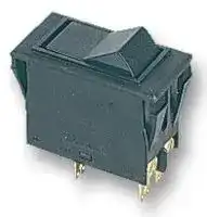
3120-F521-H7T1-W01X-16A
Thermal Circuit Breaker, 16 A, 2 Pole, 50 VDC, 250 VAC, Panel
⚠️ Reference pricing provided. In case of supply shortages, we will connect you with our trusted procurement partners to ensure your project's continuity.
- Manufacturer: ETA
- Product type: Thermal Circuit Breakers
- No. of Poles: 2 Pole
- Current Rating: 16A
- Voltage Rating VAC: 250VAC
- Voltage Rating VDC: 50VDC
- Circuit Breaker Mounting: Panel
| Delivery and price | |
|---|---|
| Units per pack | 50 |
| Price | 19.99 € |
| Current stock | 10+ |
| Lead time | 30 days |
Datasheet

**Thermal Overcurrent Circuit Breaker 3120-F...**

**1**

## **Description**

An extremely versatile range of rocker switch/thermal circuit breakers (Stype TO CBE to EN 60934 with trip free mechanism) offering the choice of single pole, double pole with single pole protection, and double pole with protection on both poles. Designed for snap-in panel mounting with versions available for three different panel cut-out sizes. Illumination is optional and there is a range of colours and markings for the rocker. Under overload conditions the rocker returns to the OFF position. 6-way frame for 3120-F5 available upon request.

Any one of the following additional function modules can be supplied factory fitted to the rear of the switch/circuit breaker.

- Under voltage release coil (for double pole versions only).

- Magnetic trip coil for short circuit protection.

- Magnetic trip coil for remote relay trip.

- Auxiliary contacts for status signalling.

- Mechanical slide interlock.

Approved to CBE standard EN 60934 (IEC 60934). Meets the requirements regarding fire resistance of EN 60335-1 : 2007-02 Safety of household and similar electrical appliances.

## **Typical applications** EE

Motors, transformers, solenoids, extra low voltage wiring systems, office machines, electro-medical equipment, power supplies, communications systems, medical equipment to EN 60601.

## **Standard current ratings and typical internal resistance values** EE

|**Current**<br>**Internal resistance**<br>**rating (A)**<br>**perpole(Ω)**|**Current**<br>**Internal resistance**<br>**rating (A)**<br>**perpole(Ω)**|
|---|---|
|0.1<br>94|4<br>0.0435|
|0.2<br>24|4.5<br>0.0435|
|0.3<br>12|5<br>0.0325|
|0.4<br>5.30|6<br>0.0215|
|0.5<br>4.20|7<br>0.0165|
|0.6<br>2.90|8<br>0.0165|
|0.8<br>1.50|10<br>< 0.02|
|0.9|12<br>< 0.02|
|1.2<br>0.80|14<br>< 0.02|
|1.5<br>0.45|15<br>< 0.02|
|0.27|16<br>< 0.02|
|2.5<br>0.0785|18<br>< 0.02|
|0.0595|20<br>< 0.02|
|3.5<br>0.0565||


## **Illumination voltage/power consumption** ~~EE~~

|**operating voltage**<br>6 V|**power consumption**<br>**Y + R**<br>2 mA|**power consumption**<br>**G**<br>3.6 mA|**T**<br>4.9 mA|
|---|---|---|---|
|12 V|2 mA|3.5 mA|4.9 mA|
|24 V|2 mA|3.5 mA|4.9 mA|
|48 V|2 mA|3.5 mA|4.9 mA|
|115 V<br>230 V|0,9 mA<br>0,9 mA|2.8 mA<br>2.8 mA|2.2 mA<br>2.2 mA|


## **Approvals**

|**Authority**<br>VDE (EN 60934)|**Voltage ratings**<br>AC 240 V; DC 28 V|**Current ratings**<br>0.1...20 A|
|---|---|---|
||DC 50 V|0.1...20 A   2-pole|
||DC 50 V|0.1...10 A   1-pole|
|UL,CSA|AC 250 V;DC 50 V|0.1...20 A|
|CCC|AC 250 V;DC 50 V|0.1...20 A|


**3120-F...**

## **Technical data** Lo

|**Technical data**<br>Lo|Lo|
|---|---|
|**For further detailsplease see cha**|**lease see chapter: Technical Information**|
|Voltage rating<br>Current ratings|AC 240 V; DC 50 V<br>(AC 415 V to special order)<br>(UL: AC 250 V;DC 50 V)<br>0.1...20 A<br>(upto 30 A to special order, singlepole only)|
|Typical life<br>AC 240 V:<br>0.1...20 A<br>DC 50 V:<br>0.1...4 A<br>4.5...16 A<br>DC 28 V:<br>4.5...20 A<br>AC 415 V:<br>0.1...16 A<br>AC 240 V:<br>0.1...16 A<br>17...20 A<br>DC 50 V:<br>0.1...16 A<br>17...20 A|**1-pole**<br>30,000 operations at 1 x IN, inductive<br>30,000 operations at 1 x IN, inductive<br>30,000 operations at 1 x IN, resistive<br>30,000 operations at 1 x IN, inductive<br>**2-pole**<br>10,000 operations at 1 x IN, inductive<br>50,000 operations at 1 x IN, inductive<br>30,000 operations at 1 x IN, inductive<br>50,000 operations at 1 x IN, inductive<br>10,000 operations at 1 x IN,inductive|
|Ambient temperature|-30...+60 °C(-22...+140 °F)|
|Insulation co-ordination      rated impulse<br>(IEC 60664 and 60664 A<br>Dielectric strength<br>(IEC 60664 and 60664A)<br>operating area                AC 3,000 V<br>betweenpoles(2-pole)AC 1|Insulation co-ordination      rated impulse<br>pollution<br>withstand voltage<br>degree<br>2.5 kV<br>2<br>reinforced insulation in operatingarea<br>test voltage<br>operating area                AC 3,000 V<br>AC 1,500 V|
|Insulation resistance|> 100 MΩ(DC 500 V)|
|Interrupting capacity Icn|0.1...2 A   10 x IN|
|Interrupting capacity|2.5...20 A  250 A 2-pole,or 150 A 1-pole<br>IN<br>UN<br>2-pole|
|(UL 1077)|0.1...2 A<br>AC 250 V<br>200 A|
||2.5...3 A<br>AC 250 V<br>1,000 A|
||3.5...8 A<br>AC 250 V<br>2,000 A|
||9...16 A<br>AC 250 V<br>3,500 A|
||18...20 A<br>AC 250 V<br>5,000 A|
||0.1...20 A<br>DC 50 V<br>1,000 A|
|Degree of protection|operating area IP40|
|(IEC 60529/DIN 40050)     (IP54 with water splash protection)|(IEC 60529/DIN 40050)     (IP54 with water splash protection)|
||terminal area IP00|
|Vibration|8 g (57-500 Hz), ± 0.61 mm (10-57 Hz)|
||to IEC 60068-2-6, test Fc|
||10 frequencycycles/axis|
|Shock|30 g (11 ms)<br>to IEC 60068-2-27,test Ea|
|Corrosion|96 hours at 5 % salt mist,|
|~~Oo~~|to IEC 60068-2-11,test Ka<br>~~Oo~~|
|Humidity|240 hours at 95 % RH,|
||to IEC 60068-2-78,test Cab|
|Mass|approx. 33 g (double pole)|
||approx. 27g (singlepole)|


Issue B(030609) **www.e-t-a.com 1** - 59 a—SSCs

**Thermal Overcurrent Circuit Breaker 3120-F...**

**1**

## **Ordering information**

## **Typical time/current characteristics**

**==> picture [503 x 628] intentionally omitted <==**

**----- Start of picture text -----**<br>
Type No.<br>3120 rocker switch/circuit breaker single or double pole load<br>Mounting<br>F snap in frame 0.1 … 2 A<br>Size of frame    panel thickness 10000 +60 °C<br>3 to fit mounting cut-out 50.5 x 21.5 mm  1-6.35 mm (.039-.250 in) +140 °F<br>5 to fit mounting cut-out 44.5 x 22 mm 1-4 mm (.039-.157 in) +23 °C<br>+73.4 °F<br>6 to fit mounting cut-out 45 x 33.7 mm 1.2-2.4 mm (.047-.094 in)<br>Number of poles 1000 -30-22 ° °CF<br>0 2-pole, unprotected, switch only<br>1 1-pole, thermally protected<br>2 2-pole, thermally protected<br>5 2-pole, thermally protected on one pole only (terminals 11,12k,12i)<br>6 1-pole, unprotected, switch only 100<br>Mounting frame design<br>1 collar height 1 mm<br>3 collar height 9 mm<br>4 collar height 2 mm with water splash protection (IP54), not with -F6... 10<br>U  with water splash protection and actuator guard<br>Terminal configuration<br>P7 blade terminals 2x2.8x0.8 mm (QC 2x.110)<br>(terminals 12(k), 22(k), 11, 21), not for under voltage  1<br>module, not for switch<br>H7 12(k), 22(k): blade terminals 2x2.8-0.8 (QC 2x.110)<br>11, 21: terminal screws, not for switch<br>N7 as P7, but including shunt terminals 12(i) and 22(i)<br>as blade terminals 2x2.8x0.8 mm (QC 2x.110) 0.1 1 2 4 6 8 10 20 40<br>not for under voltage module … times rated current<br>G7 as H7, but including shunt terminals 12(i) and 22(i)  2.5 … 20 A<br>as blade terminals 2x2.8x0.8 mm (QC 2x.110) 10000 +60 °C<br>Characteristic curve +140 °F<br>T1 thermal, 1.01-1.4 x IN +23 °C<br>Q1 switch only +73.4 °F<br>Actuator style -30 °C<br>W  rocker 1000 -22 °F<br>U momentary switch<br>Switch colour designation<br>opaque translucent<br>(for illuminated versions) 100<br>01 black      12 white<br>02 white      14 red<br>04 red 15 orange<br>16 sky blue 10<br>19 green<br>Rocker markings<br>A<br>B 0 AUS OFF<br>C I EIN ON 1<br>D<br>E 0 AUS OFF<br>F I EIN ON<br>X A B C D E F X 0.1<br>X = without marking 1 2 4 6 8 10 20 40<br>Rocker illumination (optional) … times rated current<br>G green LED<br>Y yellow LED The time/current characteristic curve depends on the ambient temperature<br>R red LED prevailing. In order to eliminate nuisance tripping, please multiply the circuit<br>T blue LED breaker current ratings by the derating factor shown below. See also<br>section 9 – Technical information.<br>Illumination voltage range<br>0 0 - 4 V  AC/DC Ambient temperature °F    -22 -4 +14 +32   +73.4 +104 +122 +140<br>1 10 - 14 V   AC/DC °C   -30 -20 -10  0 +23 +40 +50 +60<br>2 20 - 28 V   AC/DC Derating factor  0.8 0.76 0.84 0.92 1 1.08 1.16  1.24<br>3 90 - 140 V  AC<br>4 185 - 275 V  AC<br>5 42 - 54 V   AC/DC<br>Current ratings<br>0.1...20 A<br>3120 - F 3 2 1 - N7 T1  - W 14 A  R  4  - 10 A ordering example<br>3120 - F . 0 .  - N7 Q1  -W .. .    .   .  -  20 A (switch only)<br>Trip time in seconds<br>Trip time in seconds<br>**----- End of picture text -----**<br>


The time/current characteristic curve depends on the ambient temperature prevailing. In order to eliminate nuisance tripping, please multiply the circuit breaker current ratings by the derating factor shown below. See also section 9 – Technical information. Ambient temperature °F -22 -4 +14 +32   +73.4 +104 +122 +140 °C   -30 -20 -10 0 +23 +40 +50 +60 Derating factor 0.8 0.76 0.84 0.92 1 1.08 1.16  1.24

**N.B** .

Switch only versions must be specified with -N7 or -G7 terminals. Terminals 12(k) and 22(k) are not fitted.

Issue B(030609)

**1** - 60

**www.e-t-a.com**

**1**

**==> picture [112 x 38] intentionally omitted <==**

## **Thermal Overcurrent Circuit Breaker 3120-F...**

## **Internal connection diagrams**

## **Mounting style variants**

**==> picture [508 x 692] intentionally omitted <==**

**----- Start of picture text -----**<br>
2-pole, 2-pole, Style F 3.3  collar height 9 mm (.354 in.)<br>thermally protected on both poles thermally protected on one pole only 25 54<br>11 line 21 11 line 21 .98419.5 2.1335<br>.768 1.38<br>12(i) 22(i) 12(i) 22(i)<br>12(k) load 22(k) 12(k) load<br>1-pole, 2-pole, 12(i) 12(k) 11<br>thermally protected unprotected<br>11 line 11 line 21 10.7 3.5 3<br>21 .421 .138 15.5 .118<br>.827 .610<br>blade terminals DIN 46244-C-Ms-S 41<br>12(i) 22(i) (QC 2x.110) 1.61<br>12(i) 22(i) flat head screw M3.5x5-MS ISO1580<br>load tightening torque max. 0.8 Nm<br>12(k) load<br>Style F 3.4<br>collar height 2 mm (.079 in.), with water splash protection<br>27 56<br>1.06 2.21<br>Dimensions 19.5 35<br>.768 1.38<br>Style F3.1<br>collar height 1 mm/.039 in. Actuating force max. 35 N<br>25 optional illumination in ON position 12(i) 12(k) 11<br>.984 OFF position<br>16 54 10.7 3.5 3<br>.630 2.13 21 .421 .138 15.5 .118<br>.827 .610<br>blade terminals DIN 46244-C-Ms-S 41<br>(QC 2x.110) 1.61<br>flat head screw M3.5x5-MS ISO1580<br>tightening torque max. 0.8 Nm<br>Style F 5.1 25<br>.984 Optional illumination<br>16 48<br>.630 1.89<br>12(i) 12(k) 11<br>10.7 3.5 3<br>.421 .138 .118<br>21 15.5 12(i) 12(k) 11<br>.827 .610<br>blade terminals DIN 46244-C-Ms-S(QC 2x.110)flat head screw ISO1580 M3.5x5-MS 1.6141 21 .42110.7 .1383.5 15.5 .1183<br>tightening torque max. 0.8 Nm blade terminals DIN 46244-C-Ms-S.827 .610 41<br>(QC 2x.110) 1.61<br>flat head screw M3.5x5-MS ISO1580<br>tightening torque max. 0.8 Nm<br>Installation drawing  Style F 5.U<br>with water splash protection (IP54) and actuator guard<br>27 50<br>24 1.06 1.9744,2 -0,2<br>When installing the circuit breaker apply pressure on bezel only .945 21,5 [-0,1] 5,3 24,11.74 -.008<br>operating area 19,5 .846-.004 .209 .949 35<br>.768 1.38<br>12(i) 12(k) 11<br>12(i) 12(k) 11<br>10,7 3,5 3<br>.82721 .421 .138 .61015,5 .118<br>blade terminals DIN 46244-C-Ms-S 41<br>7 7 8 7 10 flat head screw M3.5x5-MS ISO1580 1.61<br>.276 .276 .315 .276 .394 tightening torque max. 0.8 Nm<br>mounting area<br>Dimension diagram for style F6 is available on request.<br>This is a metric design and millimeter dimensions take precedence  (  [mm ] inch )<br>9 .354<br>35 1.38 33 1.30<br>10 .394<br>10 .394<br>3.8 .150<br>33 1.30<br>10 .394<br>7 .276<br>35 1.38 33 1.30<br>7 .276<br>10 .394<br>35 1.38 33 1.30<br>10 .394<br>10 .394<br>37 4 .157<br>1.46 33 1.29 7 .276<br>10 .394 15.5 .610 10 .394<br>**----- End of picture text -----**<br>


Issue B(030609)

**1** - 61

**www.e-t-a.com**

**1**

## **Thermal Overcurrent Circuit Breaker 3120-F...**

## **Accessories**

**==> picture [512 x 672] intentionally omitted <==**

**----- Start of picture text -----**<br>
Rear terminal shroud black  (IP64) Insulated cover<br>Y 304 275 01 Y 303 068 01<br>2.5<br>40.5 .098<br>1.59 1.75+0.5-0.25 20.5<br>.069 [+.020] -.010 .807<br>20<br>.787<br>Terminal adapter<br>Y 303 862 01<br>4<br>ø8 .157<br>.315<br>Water splash cover, transparent  (IP66)<br>for style -F5..<br>X 221 619 01 48<br>1.89 blade terminal DIN 46244-C-Ms-S<br>(QC 2x.110)<br>Spacer for 3120-F3...<br>Y 303 675 01/02<br>58<br>ø8<br>2.28<br>.315<br>50.5<br>1.99<br>ø4.4<br>.173<br>* * Y 303 675 01 suitable for<br>panel thickness < 2 mm (.079 in)<br>* Y 303 675 02 suitable for<br>60 panel thickness < 4 mm (.157 in)<br>2.36<br>73 Spacer for 3120-F5...<br>2.87 Y 303 676 01<br>6-way frame for 3120-F5... upon request 2.0552<br>44.5<br>1.75<br>Cut-out dimensions 1<br>.039<br>Cut-out for mounting style -F3 Cut-out for mounting style -F6<br>with rocker and push button with rocker<br>--.016--.008 0.4 0.2 min. 2.5 --.016--.008 0.4 0.2 min. 2 sharp-edged<br>min .098 min .079 without bends<br>max. R2 max. R1.5<br>max .079 max .059<br>±0.05 ±0.05<br>50.5±.002+0.3 max. R0.3 ±.002“A” max. R0.3max .012 Blanking piece in -F3 frameY 303 885 31<br>1.99 +.012 max .012<br>54 matt finish 25<br>2.13 .984<br>31 16.5<br>1.22 .650<br>Cut-out for mounting style -F5<br>with rocker - 0.4<br>-.016<br>- 0.2 min. 2<br>-.008<br>min .079<br>max. R1.5 panel mm 1.2 +0.4 1.6 +0.8 2.4 +1<br>max .059 thickness inch .047+.016 .063 [+.031] .094+.039<br>1.7544.5±±0.05.002+.008+0.2 dimension“A” mminch  451.77+0,2- 0.05 [+.008] - .002 [ 45] 1.77+1.1- 0.05+.043- .002 451.77+2.2- 0.05+.087- .002 41 21<br>1.61 .827<br>max. R0.3<br>max .012<br>Edges of working parts: ISO 13715<br>All dimensions without tolerances are for reference only. In the interest of improved design,<br>R3.5<br>.138<br>9<br>.354<br>0.9 .035<br>50 1.97<br>+5 +.197<br>70 2.76<br>10 .394<br>3.7 .146<br>13.5 .531 4<br>.157<br>25 .984<br>16.5 .650<br>3.4 .134 22 .866 28 1.10<br>35 1.38<br>1 22.5 .886 28 1.10<br>.039<br>0.8 .031 2.5 .098<br>1-6.35 .039-.250 panel thickness<br>+0.2 +.008 +0.2 - 0.05 +.008 - .002<br>1<br>21.5 .846 33.7 1.33 .039<br>33 1.30 36 1.42<br> 1-4 mm .039-.157 in.<br> +0.3 +.012<br>22 .866<br>**----- End of picture text -----**<br>


All dimensions without tolerances are for reference only. In the interest of improved design, performance and cost effectiveness the right to make changes in these specifications without notice is reserved.Product markings may not be exactly as the ordering codes. Errors and omissions excepted.

This is a metric design and millimeter dimensions take precedence ~~(~~[mm ] inch ~~)~~

Issue B(030609)

**1** - 62

**www.e-t-a.com**

**Thermal Overcurrent Circuit Breaker 3120-F7..**

**1**

## **Description**

E-T-A’s proven type 3120 in a new attractive styling (S-type TO CBE to EN 60934 with trip free mechanism) offering the choice of single pole, double pole with single pole protection, and double pole with protection on both poles. Designed for snap-in panel mounting with illumination as an option. Under overload conditions the rocker returns to the OFF position. Any one of the following additional function modules can be supplied factory fitted to the rear of the switch/circuit breaker.

- Under voltage release coil (for double pole versions only).

- Magnetic trip coil for short circuit protection.

- Magnetic trip coil for remote relay trip.

- Auxiliary contacts for status signalling.

- Mechanical slide interlock.

Approved to CBE standard EN 60934 (IEC 60934).

Meets the requirements regarding fire resistance of EN 60335-1 : 2007-02 Safety of household and similar electrical appliances.

**Available accessories:** water splash protection and actuator guard to prevent inadvertent operation.

## **Typical applications**

Motors, transformers, solenoids, extra low voltage wiring systems, office machines, electro-medical equipment, power supplies, communications systems, boating.

## **Standard current ratings and typical internal resistance values** EE

|**Current**<br>**Internal resistance**<br>**rating (A)**<br>**perpole(Ω)**|**Current**<br>**Internal resistance**<br>**rating (A)**<br>**perpole(Ω)**|
|---|---|
|0.1<br>94|4<br>0.0435|
|0.2<br>24|4.5<br>0.0435|
|0.3<br>12|5<br>0.0325|
|0.4<br>5.30|6<br>0.0215|
|0.5<br>4.20|7<br>0.0165|
|0.6<br>2.90|8<br>0.0165|
|0.8<br>1.50|10<br>< 0.02|
|0.9|12<br>< 0.02|
|1.2<br>0.80|14<br>< 0.02|
|1.5<br>0.45|15<br>< 0.02|
|0.27|16<br>< 0.02|
|2.5<br>0.0785|18<br>< 0.02|
|0.0595|20<br>< 0.02|
|3.5<br>0.0565||


## **Illumination voltage/power consumption** ~~EE~~

|**operating voltage**|**power consumption**|
|---|---|
|6 V<br>12 V<br>24 V|**LED**<br>4.9 mA<br>4.9 mA<br>4.9 mA|
|48 V|4.9 mA|
|115 V|2.2 mA|
|230 V|2.2 mA|


## **Approvals**

|**Authority**|**Voltage ratings**|**Current ratings**|
|---|---|---|
|VDE (EN 60934)<br>UL,CSA<br>CCC|AC 240 V; DC 28 V<br>DC 50 V<br>DC 50 V<br>AC 250 V;DC 50 V<br>AC 250 V;DC 50 V|0.1...20 A<br>0.1...20 A   2-pole<br>0.1...10 A   1-pole<br>0.1...20 A<br>0.1...20 A|


**==> picture [45 x 9] intentionally omitted <==**

**----- Start of picture text -----**<br>
3120-F7..<br>**----- End of picture text -----**<br>


## **Technical data** Lo

|**Technical data**<br>Lo|**Technical data**<br>Lo|Lo|
|---|---|---|
|**For further detailsplease see cha**||**lease see chapter: Technical Information**|
|Voltage rating|Voltage rating|AC 240 V; DC 50 V|
|~~re~~|~~re~~|(AC 415 V to special order)<br>(UL: AC 250 V;DC 50 V)<br>~~re~~|
|Current ratings|Current ratings|0.1...20 A|
|||(upto 30 A to special order, singlepole only)|
|Typical life<br>AC 240 V:|0.1...20 A|**1-pole**<br>30,000 operations at 1 x IN, inductive|
|DC 50 V:|0.1...4 A|30,000 operations at 1 x IN, inductive|
||4.5...16 A|30,000 operations at 1 x IN, resistive|
|DC 28 V:|4.5...20 A|30,000 operations at 1 x IN, inductive|
|AC 415 V:<br>AC 240 V:|0.1...16 A<br>0.1...16 A|**2-pole**<br>10,000 operations at 1 x IN, inductive<br>50,000 operations at 1 x IN, inductive|
||17...20 A|30,000 operations at 1 x IN, inductive|
|DC 50 V:<br>0.1...16 A<br>17...20 A<br>Ambient temperature<br>Insulation co-ordination      rated impulse<br>(IEC 60664 and 60664 A||50,000 operations at 1 x IN, inductive<br>10,000 operations at 1 x IN,inductive<br>-30...+60 °C(-22...+140 °F)<br>Insulation co-ordination      rated impulse<br>pollution<br>withstand voltage<br>degree|
|||2.5 kV<br>2|
|||reinforced insulation in operatingarea|
|Dielectric strength|||
|(IEC 60664 and 60664A)<br>operating area                AC 3,000 V||test voltage<br>operating area                AC 3,000 V|
|betweenpoles(2-pole)AC 1||AC 1,500 V|
|Insulation resistance||> 100 MΩ(DC 500 V)|
|Interrupting capacity Icn||0.1...2 A   10 x IN|
|||2.5...20 A  250 A 2-pole,or 150 A 1-pole|
|Interrupting capacity<br>(UL 1077)||IN<br>UN<br>2-pole<br>0.1...2 A<br>AC 250 V<br>200 A|
|||2.5...3 A<br>AC 250 V<br>1,000 A|
|||3.5...8 A<br>AC 250 V<br>2,000 A|
|||9...6 A<br>AC 250 V<br>3,500 A|
|||18...20 A<br>AC 250 V<br>5,000 A|
|||0.1...20 A<br>DC 50 V<br>1,000 A|
|Degree of protection||operating area IP40|
|(IEC 60529/DIN 40050)     (IP54 with water splash protection)|(IEC 60529/DIN 40050)     (IP54 with water splash protection)|(IEC 60529/DIN 40050)     (IP54 with water splash protection)|
|||terminal area IP00|
|Vibration|Vibration|8 g (57-500 Hz), ± 0.61 mm (10-57 Hz)|
|||to IEC 60068-2-6, test Fc|
|||10 frequencycycles/axis|
|Shock<br>~~—~~|Shock<br>~~—~~|30 g (11 ms)<br>to IEC 60068-2-27,test Ea<br>~~—~~|
|Corrosion|Corrosion|96 hours at 5 % salt mist,|
|||to IEC 60068-2-11,test Ka|
|Humidity|Humidity|240 hours at 95 % RH,|
|||to IEC 60068-2-78,test Cab|
|Mass|Mass|approx. 33 g (double pole)|
|||approx. 27g (singlepole)|


Issue B(030609) **www.e-t-a.com 1** - 63 ~~a—SS~~ Cs

**Thermal Overcurrent Circuit Breaker 3120-F7..**

**1**

## **Ordering information**

## **Typical time/current characteristics**

**==> picture [502 x 565] intentionally omitted <==**

**----- Start of picture text -----**<br>
Type No.<br>3120 rocker switch/circuit breaker single or double pole load<br>Mounting<br>F snap in frame 0.1 … 2 A<br>Size of frame panel thickness 10000 +60 °C<br>7 to fit mounting cut-out 44.5x22 mm (1.75x.866 in) 1-4 mm (.039-.157 in) +140 °F<br>Number of poles +23 °C<br>0 2-pole, unprotected, switch only +73.4 °F<br>12 1-2-ppoleole,, thermall thermallyy pprotectedrotected 1000 -30-22 ° °CF<br>5 2-pole, thermally protected on one pole only (terminals 11,12k,12i)<br>6 1-pole, unprotected, switch only<br>Mounting frame design<br>N grey frame 100<br>P snap-on actuator guard grey<br>Q snap-on water splash cover grey<br>R black frame<br>S snap-on actuator guard black 10<br>T snap-on water splash cover black<br>Terminal configuration<br>P7 blade terminals 2x2.8x0.8 mm (QC 2x.110) (terminals<br>12(k), 22(k),11, 21), not for under voltage module,  1<br>not for switch<br>H7 12(k), 22(k): blade terminals 2x2.8-0.8 (QC 2x.110)<br>11, 21: terminal screws, not for switch<br>N7 as P7, but including shunt terminals 12(i) and 22(i)<br>as blade terminals 2x2.8x0.8 mm (QC 2x.110) 0.1<br>1 2 4 6 8 10 20 40<br>not for under voltage module<br>… times rated current<br>G7 as H7, but including shunt terminals 12(i) and 22(i)  2.5 … 20 A<br>as blade terminals 2x2.8x0.8 mm (QC 2x.110) 10000 +60 °C<br>Characteristic curve +140 °F<br>T1 thermal, 1.01-1.4 x IN +23 °C<br>Q1 switch only +73.4 °F<br>Actuator style -30 °C<br>A rocker 1000 -22 °F<br>Switch colour designation<br>opaque translucent<br>20 blue  30 blue<br>26 sky blue 36 sky blue 100<br>Rocker markings<br>I 10<br>0<br>Q<br>Q "I" and "0" moulded in 1<br>Push button illumination (optional)<br>T blue LED<br>Illumination voltage range (optional)<br>0 4 - 7 V  0.1<br>1 10 - 14 V      1 2 4 6 8 10 20 40<br>2 20 - 28 V      … times rated current<br>3 90 - 140 V<br>4 185 - 275 V<br>5 42 - 54 V   AC/DC     The time/current characteristic curve depends on the ambient temperature<br>Current ratings prevailing. In order to eliminate nuisance tripping, please multiply the circuit<br>0.1...20 A breaker current ratings by the derating factor shown below. See also<br>section 9 – Technical information.<br>3120 - F 7 2  N - N7 T1  - A 30 Q T 4  - 10 A ordering example Ambient temperature °F    -22 -4 +14 +32   +73.4 +104 +122 +140<br>°C   -30 -20 -10  0 +23 +40 +50 +60<br>3120 - F . 0  N  - N7 Q1  -A 30 Q   T 4  -  20 A (switch only) Derating factor  0.8 0.76 0.84 0.92 1 1.08 1.16  1.24<br>Trip time in seconds<br>Trip time in seconds<br>**----- End of picture text -----**<br>


The time/current characteristic curve depends on the ambient temperature prevailing. In order to eliminate nuisance tripping, please multiply the circuit breaker current ratings by the derating factor shown below. See also section 9 – Technical information.

Ambient temperature °F -22 -4 +14 +32   +73.4 +104 +122 +140 °C   -30 -20 -10 0 +23 +40 +50 +60 Derating factor 0.8 0.76 0.84 0.92 1 1.08 1.16  1.24

## **N.B.**

Switch only versions must be specified with -N7 or -G7 terminals. Terminals 12(k) and 22(k) are not fitted.

Issue B(030609)

**1** - 64

**www.e-t-a.com**

**1**

**==> picture [112 x 38] intentionally omitted <==**

## **Thermal Overcurrent Circuit Breaker 3120-F7..**

## **Dimensions**

**==> picture [225 x 593] intentionally omitted <==**

**----- Start of picture text -----**<br>
Style -F7.N and F7.R<br>25 48 [±][0.2]<br>.984 1.89 [±][.008]<br>15.5 44.2 -0.2<br>.610 1.74 -.008<br>LINE<br>12(i) 12(k) 11<br>10.7 3.5 3<br>.421 .138 .118<br>21 15.5<br>.827 .610<br>41<br>blade terminals DIN 46244-C-Ms-S 1.61<br>(QC 2 x .110)<br>flat head screw ISO1580 M3.5x5-MS<br>tightening torque max. 0.8 Nm<br>Style -F7.P and F7.S<br>34 60<br>1.34 2.36<br>18.8 44.2 -0,2<br>.740 1.74 -.008<br>15.5<br>.610<br>LINE<br>12(i) 12(k) 11<br>10.7 3.5 3<br>.421 .138 .118<br>21 15.5<br>.827 .610<br>41<br>1.61<br>blade terminals DIN 46244-C-Ms-S<br>(QC 2 x .110)<br>flat head screw ISO1580 M3.5x5-MS<br>tightening torque max. 0.8 Nm<br>Style -F7.Q and F7.T<br>34 60<br>1.34 2.36<br>18.6 44.8<br>.732 1.76<br>LINE<br>12(i) 12(k) 11<br>10.7 3.5 3<br>.421 .138 .118<br>21 15.5<br>.827 .610<br>41<br>blade terminals DIN 46244-C-Ms-S 1.61<br>(QC 2 x .110)<br>flat head screw ISO1580 M3.5x5-MS<br>tightening torque max. 0.8 Nm<br>8.9 .350 3<br>.118<br>33 1.30<br>10 .394<br>8.9 .350<br>33 1.30 5.9 .232<br>10 .394<br>11.5 .453<br>33 1.30<br>10 .394<br>**----- End of picture text -----**<br>


## **Internal connection diagrams**

**==> picture [249 x 582] intentionally omitted <==**

**----- Start of picture text -----**<br>
2-pole, 2-pole,<br>thermally protected on both poles thermally protected on one pole only<br>11 line 21 11 line 21<br>12(i) 22(i) 12(i) 22(i)<br>12(k) load 22(k) 12(k) load<br>1-pole, 2-pole,<br>thermally protected unprotected<br>line line<br>11 11 21<br>12(i) 22(i)<br>12(i) 22(i)<br>load<br>12(k) load<br>Installation drawing<br>When installing the circuit breaker apply pressure on bezel only.<br>operating area<br>LINE<br>12(i) 12(k) 11<br>7 7 8 7 10<br>.276 .276 .315 .276 .394<br>mounting area<br>Panel cut-out<br>-0,4<br>-.016-.008-0,2 min. 2<br>min .079<br>max. R1.5<br>±±0.002,05 max .059<br>44.5 [+0.4]<br>max. R0.3<br>1.75 [+.016] max .012<br>Edges of working parts: ISO 13715<br>10<br>15.5<br>1- 4<br>.039 - .157<br>+0.3 +.012<br>22 .866<br>.394<br>.610<br>**----- End of picture text -----**<br>


This is a metric design and millimeter dimensions take precedence ~~(~~[mm ] inch ~~)~~

Issue B(030609)

**1** - 65

**www.e-t-a.com**

**1**

## **Thermal Overcurrent Circuit Breaker 3120-F7..**

## **Accessories**

## **Insulated cover Y 303 068 01**

**==> picture [208 x 333] intentionally omitted <==**

**----- Start of picture text -----**<br>
2.5<br>.098<br>20<br>.787<br>Terminal adapter<br>Y 303 862 01<br>4<br>.157<br>blade terminal DIN 46244-C-Ms-S<br>(QC 2x.110)<br>Spacer<br>Y 303 676 01<br>52<br>2.05<br>44.5<br>1.75<br>1<br>.039<br>sharp-edged<br>without bends<br>R3.5<br>.138<br>9<br>.354<br>0.9 .035<br>3.7 .146<br>13.5 .531 4<br>.157<br>1 22.5 .886 28 1.10<br>.039<br>0.8 .031 2.5 .098<br>**----- End of picture text -----**<br>


**==> picture [189 x 342] intentionally omitted <==**

**----- Start of picture text -----**<br>
Translucent water splash cover  (IP54)<br>X 222 143 01<br>Consisting of<br>- Y 307 097 01 snap-on frame with actuator guard<br>- Y 307 096 01 soft plastic cover<br>18.8 11.5<br>.740 .453<br>34 10.1<br>1.34 .398<br>Snap-on frame with actuator guard<br>as switch-on protection or switch-off protection)<br>Y 307 097 01<br>18.8 5.9<br>.740 .232<br>34 10.1<br>1.34 .398<br>60 2.36<br>60 2.36<br>**----- End of picture text -----**<br>


**Snap-on frame with actuator guard** (can be snapped on as switch-on protection or switch-off protection) **Y 307 097 01**

**Rear terminal shroud black** (IP64) **Y 304 275 01**

**==> picture [146 x 124] intentionally omitted <==**

**----- Start of picture text -----**<br>
40.5<br>1.59 1.75+0.5-0.25 20.5<br>.069 [+.020] -.010 .807<br>ø8<br>.315<br>50 1.97<br>+5 +.197<br>70 2.76<br>10 .394<br>**----- End of picture text -----**<br>


This is a metric design and millimeter dimensions take precedence ~~(~~[mm ] inch ~~)~~

All dimensions without tolerances are for reference only. In the interest of improved design, performance and cost effectiveness the right to make changes in these specifications without notice is reserved.Product markings may not be exactly as the ordering codes. Errors and omissions excepted.

Issue B(030609)

**1** - 66

**www.e-t-a.com**

**Thermal Overcurrent Circuit Breaker 3120-F...**

**1**

## **Description**

Switch/thermal trip free circuit breaker (S-type TO CBE to EN 60934) with standard isolator style two button operation. Single button press-to-reset version also available. Both types can be supplied in single pole configuration only, in double pole with single pole protection, and in double pole with protection on both poles. Designed for snap-in panel mounting. There is a choice of push button colour combinations and illumination is optional. Any one of the following additional function modules can be supplied factory fitted to the rear of the switch/circuit breaker:

- Under voltage release coil (for double pole versions only).

- Magnetic trip coil for short circuit protection.

- Magnetic trip coil for remote relay trip.

- Auxiliary contacts for status signalling.

- Mechanical slide interlock.

**==> picture [41 x 9] intentionally omitted <==**

**----- Start of picture text -----**<br>
3120-F...<br>**----- End of picture text -----**<br>


Approved to CBE standard EN 60934 (IEC 60934). Meets the requirements regarding fire resistance of EN 60335-1 : 2007-02 Safety of household and similar electrical appliances. **Technical data Typical applications** ~~LS~~ Motors, transformers, solenoids, extra low voltage wiring systems, office ~~Lo~~ **For further details** Voltage rating ~~eee~~ **please see cha** AC 240 V; DC 50 V **pter: Technical Information** machines, electro-medical equipment, power supplies, communications (AC 415 V to special order) (UL: AC 250 V; DC 50 V)

Motors, transformers, solenoids, extra low voltage wiring systems, office machines, electro-medical equipment, power supplies, communications systems, industrial controls.

|Voltage rating|Voltage rating|AC 240 V; DC 50 V<br>(AC 415 V to special order)<br>(UL: AC 250 V; DC 50 V)UL: AC 250 V; DC 50 V); DC 50 V)DC 50 V))|
|---|---|---|
|Current ratings|Current ratings|0.1...20 A|
|Typical life<br>AC 240 V:|0.1...20 A|(upto 30 A to special order, singlepole only)<br>**1-pole**<br>30,000 operations at 1 x IN, inductive|
|DC 50 V:<br>DC 28 V:|0.1...4 A<br>4.5...16 A<br>4.5...20 A|30,000 operations at 1 x IN, inductive<br>30,000 operations at 1 x IN, resistive<br>30,000 operations at 1 x IN, inductive<br>**2-pole**|
|AC 415 V:|0.1...16 A|10,000 operations at 1 x IN, inductive|
|AC 240 V:<br>DC 50 V:|0.1...16 A<br>17...20 A<br>0.1...16 A|50,000 operations at 1 x IN, inductive<br>30,000 operations at 1 x IN, inductive<br>50,000 operations at 1 x IN, inductive|
||17...20 A|10,000 operations at 1 x IN,inductive|
|Ambient temperature||-30...+60 °C(-22...+140 °F)|
|Insulation co-ordination      rated impulse||Insulation co-ordination      rated impulse<br>pollution|
|(IEC 60664 and 60664 A|(IEC 60664 and 60664 A|withstand voltage<br>degree<br>2.5 kV<br>2|
|||reinforced insulation in operatingarea|
|Dielectric strength|||
|(IEC 60664 and 60664A)|(IEC 60664 and 60664A)|test voltage|
|operating area                AC 3,000 V||operating area                AC 3,000 V|
|betweenpoles(2-pole)AC 1||AC 1,500 V|
|Insulation resistance||> 100 MΩ(DC 500 V)|
|Interrupting capacity Icn||0.1...2 A   10 x IN|
|Interrupting capacity<br>(UL 1077)||2.5...20 A  250 A 2-pole,or 150 A 1-pole<br>IN<br>UN<br>2-pole<br>0.1...2 A<br>AC 250 V<br>200 A|
|||2.5...3 A<br>AC 250 V<br>1,000 A<br>3.5...8 A<br>AC 250 V<br>2,000 A<br>9...16 A<br>AC 250 V<br>3,500 A<br>18...20 A<br>AC 250 V<br>5,000 A|
|||0.1...20 A<br>DC 50 V<br>1,000 A|
|Degree of protection||operating area IP40|
|(IEC 60529/DIN 40050|IEC 60529/DIN 40050)terminal area IP00|terminal area IP00|
|Vibration|Vibration|8 g (57-500 Hz), ± 0.61 mm (10-57 Hz)<br>to IEC 60068-2-6, test Fc<br>10 frequencycycles/axis|
|Shock|Shock|30 g (11 ms)|
|||to IEC 60068-2-27,test Ea|
|Corrosion|Corrosion|96 hours at 5 % salt mist,|
|||to IEC 60068-2-11,test Ka|
|Humidity|Humidity|240 hours at 95 % RH,<br>to IEC 60068-2-78,test Cab|
|Mass|Mass|approx. 33 g (double pole)|


## **Standard current ratings and typical internal resistance values** EE

|**Current**<br>**Internal resistance**<br>**rating (A)**<br>**perpole(Ω)**|**Current**<br>**Internal resistance**<br>**rating (A)**<br>**perpole(Ω)**|
|---|---|
|0.1<br>94|4<br>0.0435|
|0.2<br>24|4.5<br>0.0435|
|0.3<br>12|5<br>0.0325|
|0.4<br>5.30|6<br>0.0215|
|0.5<br>4.20|7<br>0.0165|
|0.6<br>2.90|8<br>0.0165|
|0.8<br>1.50|10<br>< 0.02|
|0.9|12<br>< 0.02|
|1.2<br>0.80|14<br>< 0.02|
|1.5<br>0.45|15<br>< 0.02|
|0.27|16<br>< 0.02|
|2.5<br>0.0785|18<br>< 0.02|
|0.0595|20<br>< 0.02|
|3.5<br>0.0565||


## **Illumination voltage/power consumption** ~~EE~~

|**operating voltage**|**power consumption**|**power consumption**|
|---|---|---|
||**Y + R**|**G**|
|6 V|2 mA|3.6 mA|
|12 V|2 mA|3.5 mA|
|24 V|2 mA|3.5 mA|
|48 V|2 mA|3.5 mA|
|115 V|0.9 mA|2.8 mA|
|230 V|0.9 mA|2.8 mA|


## **Approvals**

|**Authority**|**Voltage ratings**|**Current ratings**|
|---|---|---|
|VDE (EN 60934)|AC 240 V; DC 28 V|0.1...20 A|
||DC 50 V|0.1...20 A   2-pole|
||DC 50 V|0.1...10 A   1-pole|
|UL,CSA|AC 250 V;DC 50 V|0.1...20 A|
|CCC|AC 250 V;DC 50 V|0.1...20 A|


approx. 27 g (single pole)

Issue B(030609) **www.e-t-a.com 1** - **67** —SSCs

**Thermal Overcurrent Circuit Breaker 3120-F...**

**1**

**==> picture [249 x 18] intentionally omitted <==**

**----- Start of picture text -----**<br>
Typical time/current characteristics<br>**----- End of picture text -----**<br>


## **Ordering information**

**==> picture [504 x 520] intentionally omitted <==**

**----- Start of picture text -----**<br>
Type No.<br>3120 push button switch/circuit breaker single or double pole load<br>Mounting<br>F snap in frame 0.1 … 2 A<br>Size of frame 10000 +60 °C<br>2 flange mounting, special frame for fitting splash cover +140 °F<br>3 to fit mounting cut-out 50.5 x 21.5 mm (1.99 x 8.47 in) +23 °C<br>panel thickness 1 - 6.35 mm (.039 - .250 in) +73.4 °F<br>Number of poles 1000 -30-22 ° °CF<br>0 2-pole, unprotected, switch only<br>1 1-pole, thermally protected<br>2 2-pole, thermally protected<br>5 2-pole, thermally protected on one pole only (terminals 11,12k,12i)<br>6 1-pole, unprotected, switch only 100<br>Mounting frame design<br>F with 2 push buttons<br>G with 1 push button (switch-on only)<br>Terminal configuration 10<br>P7 blade terminals 2x2.8x0.8 mm (QC 2x.110)<br>(terminals 12(k), 22(k), 11, 21), not for under voltage<br>module, not for switch<br>H7 12(k), 22(k): blade terminals 2x2.8-0.8 (QC 2x.110) 1<br>11, 21: terminal screws, not for switch<br>N7 as P7, but including shunt terminals 12(i) and 22(i)<br>as blade terminals 2x2.8x0.8 mm (QC 2x.110)<br>not for under voltage module<br>G7 as H7, but including shunt terminals 12(i) and 22(i)  0.1 1 2 4 6 8 10 20 40<br>as blade terminals 2x2.8x0.8 mm (QC 2x.110) … times rated current<br>Characteristic curve 2.5 … 20 A<br>T1 thermal, 1.01-1.4 IN 10000 +60 °C<br>Q1 switch only, only for N7 or G7 terminals +140 °F<br>Switch style/colour +23 °C<br>D 1 push button (re-set only) +73.4 °F<br>Z 1 push button (momentary switch) -30 °C<br>01X black 1000 -22 °F<br>04X red<br>12X white translucent<br>19X green translucent<br>S 2 push buttons on/off 100<br>GRX green translucent/red<br>WRX white translucent/red<br>WBX white translucent/black<br>Push button illumination (optional) 10<br>G green LED, AC/DC<br>Y yellow LED, AC/DC<br>R red LED, AC/DC<br>Illumination voltage range (optional)<br>0 0 - 4 V  AC/DC 1<br>1 10 - 14 V  AC/DC<br>2 20 - 28 V  AC/DC<br>3 90 - 140 V  AC<br>4 185 - 275 V AC 0.1<br>5 42 - 54 V  AC/DC 1 2 4 6 8 10 20 40<br>Current ratings … times rated current<br>0.1...20 A<br>The time/current characteristic curve depends on the ambient temperature<br>3120 - F 3 2 F  - N7 T1  - S GRX G 4  - 10 A ordering example prevailing. In order to eliminate nuisance tripping, please multiply the circuit<br>3120 - F 3 0 F  - N7 Q1 - S ... .   .  - 20 A switch only breaker current ratings by the derating factor shown below. See also<br>Trip time in seconds<br>Trip time in seconds<br>**----- End of picture text -----**<br>


The time/current characteristic curve depends on the ambient temperature prevailing. In order to eliminate nuisance tripping, please multiply the circuit breaker current ratings by the derating factor shown below. See also section 9 – Technical information. Ambient temperature °F -22 -4 +14 +32   +73.4 +104 +122 +140 °C   -30 -20 -10 0 +23 +40 +50 +60 Derating factor 0.8 0.76 0.84 0.92 1 1.08 1.16  1.24

## **N.B.**

Switch only versions must be specified with -N7 or -G7 terminals. Terminals 12(k) and 22 (k) are not fitted.

Issue B(030609)

**1** - 68

**www.e-t-a.com**

**1**

**==> picture [112 x 38] intentionally omitted <==**

## **Thermal Overcurrent Circuit Breaker 3120-F...**

## **Dimensions**

**==> picture [226 x 630] intentionally omitted <==**

**----- Start of picture text -----**<br>
3120-F3.F-…-S…<br>actuating force max. 35 N<br>OFF position optional illumination in ON position<br>25 54<br>.984 2.13<br>16.2 14.2<br>.638 .559<br>12(i) 12(k) 11<br>10.7 3.5 3<br>21 .421 .138 15.5 .118<br>.827 .610<br>blade terminals DIN 46244-C-Ms-S 41<br>(QC 2x.110) 1.61<br>flat head screw ISO1580 M3.5x5-MS<br>tightening torque max. 0.8 Nm<br>3120-F3.G-…-D…<br>OFF position optional illumination in ON position<br>25 54<br>.984 2.13<br>16.2 14.2<br>.638 .559<br>12(i) 12(k) 11<br>10.7 3.5 3<br>21 .421 .138 15.5 .118<br>.827 .610<br>blade terminals DIN 46244-C-Ms-S 41<br>(QC 2x.110) 1.61<br>flat head screw ISO1580 M3.5x5-MS<br>tightening torque max. 0.8 Nm<br>3120-F2.F-… water splash cover<br>retaining clip (see next page)<br>panel<br>cover<br>35.4 74<br>1.39 2.91<br>16.2 60 [±][0.1]<br>.638 2.36 [±][.004]<br>ø3.2<br>.126<br>PT-screw<br>Typ K40 12(i) 12(k) 11<br>ø4mm<br>(.157 in.)<br>10.7 3.5 3<br>.421 .138 .118<br>21 15.5<br>.827 .610<br>blade terminals DIN 46244-C-Ms-S 41<br>(QC 2x.110) 1.61<br>flat head screw ISO1580 M3.5x5-MS<br>tightening torque max. 0.8 Nm<br>10 .394<br>15 .591<br>33 1.30<br>10 .394<br>10 .394<br>15 .591<br>33 1.30<br>10 .394<br>10 .394<br>15 .591<br>10.2 .402<br>4.5 .177<br>33 1.30<br>10 .394<br>**----- End of picture text -----**<br>


## **Internal connection diagrams**

**==> picture [249 x 176] intentionally omitted <==**

**----- Start of picture text -----**<br>
2-pole, 2-pole,<br>thermally protected on both poles thermally protected on one pole only<br>11 line 21 11 line 21<br>12(i) 22(i) 12(i) 22(i)<br>12(k) load 22(k) 12(k) load<br>1-pole, 2-pole,<br>thermally protected unprotected<br>line line<br>11 11 21<br>12(i) 22(i)<br>12(i) 22(i)<br>load<br>12(k) load<br>**----- End of picture text -----**<br>


## **Installation drawing**

**==> picture [249 x 444] intentionally omitted <==**

**----- Start of picture text -----**<br>
When installing the circuit breaker apply pressure on bezel only.<br>operating area<br>12(i) 12(k) 11<br>7 7 8 7 10<br>.276 .276 .315 .276 .394<br>mounting area<br>Panel cut-out<br>3120-F3… - 0.4<br>-.016<br>- 0.2<br>-.008 min. 2.5<br>min .098<br>max. R2<br>±0.05 max .079<br>±.002<br>50.5 +0.3<br>1.99 +.012<br>max. R0.3<br>max .012<br>3120-F2… t: metal min. 2 mm (.079 in.)<br>plastic min. 3 mm (.118 in.)<br>60 [±][0.15]<br>2.36 [+.006]<br>50.5 [+0.5] R2<br>1.99 +.020 .079<br>Edges of working parts: ISO 13715<br>10 .394<br>15.5 .610<br>1-6.35 .039-.250 +0.2 +.008<br>21.5 .846<br>t<br> +0.2  +.008<br>+0.2 +.008 ø4.3 .169<br>26 1.02<br>**----- End of picture text -----**<br>


This is a metric design and millimeter dimensions take precedence ~~(~~[mm ] inch ~~)~~

Issue B(030609)

**1** - 69

**www.e-t-a.com**

## **Thermal Overcurrent Circuit Breaker 3120-F...**

## **Accessories**

**1**

**==> picture [431 x 405] intentionally omitted <==**

**----- Start of picture text -----**<br>
Insulated cover Rear terminal shroud black  (IP64)<br>Y 303 068 01 Y 304 275 01<br>2.5<br>.098 40.5<br>1.59 1.75+0.5-0.25 20.5<br>.069 [+.020] -.010 .807<br>20<br>.787<br>Terminal adapter<br>Y 303 862 01<br>4<br>.157<br>ø8<br>.315<br>Water splash cover, transparent  (IP66) f<br>X 221 619 01<br>(QC 2x.110)blade terminal DIN 46244-C-Ms-S consisting of<br>- retaining clip Y 306 551 01<br>- cover Y 306 001 01<br>Spacer for 3120-F3...Y 303 675 01/02 1.8948<br>58<br>2.28<br>50.5<br>1.99<br>ø8<br>.315<br>ø4.4<br>.173<br>* * Y 303 675 01 suitable for<br>panel thickness < 2 mm (.079 in)<br>* Y 303 675 02 suitable for<br>panel thickness < 4 mm (.157 in)<br>Blanking piece in -F3 frame 60<br>Y 303 885 31 2.36<br>73<br>54 25 2.87<br>R3.5<br>.138<br>9<br>.354<br>0.9 .035<br>50 1.97<br>+5 +.197<br>70 2.76<br>10 .394<br>3.7 .146<br>13.5 .531 4<br>.157<br>25 .984<br>22 .866 28 1.10 16.5 .650<br>3.4 .134<br>35 1.38<br>**----- End of picture text -----**<br>


**Water splash cover, transparent** (IP66) f **or style 3120-F2.F-... X 221 619 01 consisting of**

**==> picture [223 x 115] intentionally omitted <==**

**----- Start of picture text -----**<br>
54 matt finish 25<br>2.13 .984<br>31 16.5<br>1.22 .650<br>41 21<br>1.61 .827<br>1<br>.039<br>33 1.30 36 1.42<br>**----- End of picture text -----**<br>


This is a metric design and millimeter dimensions take precedence ~~(~~[mm ] inch ~~)~~

All dimensions without tolerances are for reference only. In the interest of improved design, performance and cost effectiveness the right to make changes in these specifications without notice is reserved.Product markings may not be exactly as the ordering codes. Errors and omissions excepted.

Issue B(030609)

**1** - 70

**www.e-t-a.com**

**1**

**==> picture [112 x 38] intentionally omitted <==**

## **Auxiliary Contact Module X3120-S for circuit breaker 3120-F...**

## **Description**

A module supplied factory fitted to type 3120-F to provide electrically separate changeover contacts which operate as the main contacts open/ close. Ideally suited to status signalling and sequence switching.

## **Typical applications**

Monitoring of the switching position of the circuit breaker or any connected load.

## **Ordering information**

## **Type No.**

- **X3120** Module for type 3120 and type 3140

**==> picture [248 x 171] intentionally omitted <==**

**----- Start of picture text -----**<br>
Function<br>S auxiliary contact module<br>Contact configuration<br>0 change-over contact<br>Terminal design<br>1 blade terminals 2.8 x 0.5 (QC .110), silver plated<br>Contact rating<br>AC DC  (not approved)<br>Voltage rating Current rating  Voltage rating  Current rating<br>12 V 0.1...4 A<br>24 V 0.1...4 A<br>A 10 V-250 V 0.1...4 A 60 V 0.1...1 A<br>110 V 0.1...0,5 A<br>220 V 0.1...0.25 A<br>B 5 V-250 V 0.05...1 A 5 V-250 V 0.05...1 A<br>Supply condition<br>M module mounted to circuit breaker 3120-...<br>X3120 - S 0 1 A M ordering example<br>**----- End of picture text -----**<br>


## **Approvals (complete circuit breaker/module assembly)**

## **Dimensions**

**==> picture [249 x 185] intentionally omitted <==**

**----- Start of picture text -----**<br>
21 10<br>.827 .394<br>14<br>.551<br>blade terminalsDIN 46244-A2.8-0.5-Ms (QC .110)<br>silver plated<br>7.5 7.5<br>.295 .295 2<br>19.8 .079<br>.780<br>25.5 1.00<br>8.5 .335<br>**----- End of picture text -----**<br>


## **Internal connection diagram**

**==> picture [249 x 114] intentionally omitted <==**

**----- Start of picture text -----**<br>
line<br>11 21 34 32<br>module mounted<br>12(i) 22(i) 31<br>12(k) 22(k)<br>load<br>**----- End of picture text -----**<br>


## **Technical data**

|**Authority**|**Voltage ratings**|**Current ratings**|
|---|---|---|
|VDE(EN 60934)|AC 250 V;DC 28 V|0.05...4 A|
|UL,CSA|AC 250 V|0.05...4 A|


|Voltage rating|AC 250 V; DC 220 V|
|---|---|
|Current rating|0.1...4 A  / 0.05...1 A|
|Typical life|50,000 operations|
|Ambient temperature|-30...+60 °C(-22...+140 °F)|
|Dielectric strength||
|(IEC 60664 and 60664A)|test voltage|
|between main and||
|auxiliarycircuit|AC 3,000 V|
|Insulation resistance|> 100 MΩ(DC 500 V)|
|Vibration|6 g (type X3120-S...A)|
||8 g (type X3120-S...B)|
||(57-500 Hz), ± 0.46 mm (10-57 Hz)|
||to IEC 60068-2-6, test Fc|
||10 frequencycycles/axis|
|Shock|15 g (11 ms), type X3120-S...A|
||20 g (11 ms), type X3120-S...B|
||to IEC 60068-2-27,test Ea|
|Corrosion|96 hours at 5 % salt mist,|
||to IEC 60068-2-11,test Ka|
|Humidity|240 hours at 95 % RH|
||to IEC 60068-2-78,test Cab|
|Mass|approx. 38g (complete assembly)|


This is a metric design and millimeter dimensions take precedence ~~(~~[mm ] inch ~~)~~

All dimensions without tolerances are for reference only. In the interest of improved design, performance and cost effectiveness the right to make changes in these specifications without notice is reserved.Product markings may not be exactly as the ordering codes. Errors and omissions excepted.

Issue B(030609)

**1** - 71

**www.e-t-a.com**

**1**

## **Undervoltage Release Module X3120-U...for circuit breaker 3120-F...**

## **Description**

A module suitable for all double pole versions of type 3120-F to trip the main switch/circuit breaker mechanism in the event of loss of voltage. When the voltage is restored the rocker switch must be reset to reconnect the load, thereby avoiding the safety hazards associated with automatic re-starting of machinery.

**Note:** Basic unit 3120-...-H7 or -G7: screw terminals necessary.

## **Typical applications**

Machines such as power tools, industrial equipment and domestic appliances where automatic restart after restoration of power could be dangerous (EC Machinery Directive).

## **Ordering information**

## **Type No.**

**X3120** Module for type 3120 **Function U** undervoltage release module **Terminal design 00** standard (without separate connections) **01** 1 blade terminal 2.8x0.8 (QC .110) **02** 2 blade terminals 2.8x0.8 (QC .110) **Voltage ratings 00** AC 230/240 V  50/60 Hz **01** AC 120 V  50/60 Hz **02** AC 100 V  50/60 Hz **03** DC 24 V **Assembly status M** module mounted to the circuit breaker 3120

**X3120  -U  00 00    M** ordering example

## **Approvals  (complete circuit breaker/module assembly)**

## **Dimensions**

**==> picture [249 x 185] intentionally omitted <==**

**----- Start of picture text -----**<br>
for mains connectionflat head screw M3.5x5-MS ISO1580 41 +0.1- 0.2<br>tightening torque max. 0.8 Nm 1.61 [+.004] - .008<br>6.6<br>10.7<br>.260 21 .421 blade terminal<br>.827 21 DIN 46244-A2.8-0.8<br>22 .827 (QC .110)<br>2 terminals 1 terminal<br>.866 X3120-U02… X3120-U01…<br>23.5<br>.925<br>Without terminal(s): X3120-U00…<br>33.5 1.32 15°<br>7.6 .299<br>**----- End of picture text -----**<br>


## **Internal connection diagrams**

**==> picture [249 x 114] intentionally omitted <==**

**----- Start of picture text -----**<br>
X3120-U00… X3120-U01… X3120-U02…<br>line line line line line<br>11 21 11 A2s 21 11 A1 A2 21<br>12(i) 22(i) 12(i) 22(i) 12(i) 22(i)<br>12(k) 22(k) 12(k) 22(k) 12(k) 22(k)<br>load load load<br>U< U< U<<br>**----- End of picture text -----**<br>


## **Technical data**

**Authority Voltage ratings** VDE (EN 60934) AC 100...240 V; DC 24 V UL, CSA AC 100...240 V; DC 24 V

|Voltage ratings|AC 100; 120 V; 230/240 V 50/60 Hz|
|---|---|
||DC 24 V|
|Voltage tolerance|+10%/-15%|
|Current consumption|approx. 2.5 mA|
|Typical life|20,000 operations|
|Release values|0.2 x UN < U < 0.7 x UN|
||(at a rated voltage of AC 100 V the|
||device may release at 70 V and|
||must release at 20 V)|
|Release delay|t < 20 ms|
|Latch-in values|≥ 85 % UN|
|Ambient temperature|-30...+60 °C(-22...+140 °F)|
|Vibration|8 g (57-500 Hz) ± 0.61 mm (10-57 Hz)|
||to IEC 60068-2-6, test Fc|
||10 frequencycycles/axis|
|Shock|30 g (11 ms)|
||to IEC 60068-2-27,test Ea|
|Corrosion|48 hours at 5 % salt mist,|
||to IEC 60068-2-11,test Ka|
|Humidity|240 hours at 95% RH|
||to IEC 60068-2-78,test Cab|
|Mass|approx. 53g (complete assembly)|


This is a metric design and millimeter dimensions take precedence ([mm ] inch ~~)~~

All dimensions without tolerances are for reference only. In the interest of improved design, performance and cost effectiveness the right to make changes in these specifications without notice is reserved.Product markings may not be exactly as the ordering codes. Errors and omissions excepted.

Issue B(030609)

**1** - 72

**www.e-t-a.com**

**1**

**==> picture [112 x 38] intentionally omitted <==**

## **Remote Trip Module X3120-M... for circuit breaker 3120-F...**

## **Description**

A module which adds remote trip capability to all versions of type 3120-F. A voltage applied across the coil, by means of an external sensor for example, will cause disconnection of the main switch/circuit breaker mechanism.

## **Typical applications**

Electrical monitoring of safety systems, remote trip.

## **Ordering information**

## **Type No.**

**X3120** Module for type 3120 **Function M** magnetic relay trip module **Style 2** magnetic remote trip coil **Terminal design P7** blade terminals 2x2.8x0.8 (QC 2x.110) tin plated **Supply condition M** module mounted to the circuit breaker **Voltage ratings AC 12, 24, 48, 60, 120, 220, 230, 240 V DC 12, 24 V X3120 - M 2 P7    M  - 12 V** ordering example

## **Standard voltage ratings and typical internal resistance values**

|**oltage**<br>**Internal**<br>**ating**<br>**resistance per**<br>**V)**<br>**pole(Ω)**|**Voltage**<br>**Internal**<br>**rating**<br>**resistance per**<br>**(V)**<br>**pole(Ω)**|
|---|---|
|2 V AC/DC<br>0.78|120 V AC<br>71.0|
|4 V AC/DC<br>3.3|220 V AC<br>312|
|8 V AC<br>11.9|230 V AC<br>312|
|0 V AC<br>18.5|240 V AC<br>312|


## **Approvals  (complete circuit breaker/module assembly)**

|**Authority**|**Voltage ratings**|
|---|---|
|VDE(EN 60934)|AC 12...240 V;DC 12...24 V|
|UL,CSA|AC 12...240 V;DC 12...24 V|


## **Dimensions**

**==> picture [249 x 185] intentionally omitted <==**

**----- Start of picture text -----**<br>
10.7 18<br>blade terminals .421 .709<br>DIN 46244-C-Ms-S 21 14<br>(QC 2x.110) .827 .551<br>30 1.18<br>9<br>.354<br>**----- End of picture text -----**<br>


## **Internal connection diagram**

**==> picture [249 x 126] intentionally omitted <==**

**----- Start of picture text -----**<br>
line<br>11 21<br>12(i) 22(i)<br>12(k) load 22(k)<br>12(n)<br>FA remote trip<br>module<br>mounted 12<br>**----- End of picture text -----**<br>


## **Technical data**

|Voltage ratings|AC 12...240 V; DC 12...24 V|
|---|---|
|Power consumption|approx. 200 W|
|Pulse operation|20 ms < tON< 100 ms/tOFF > 10 sec|
|Release delay|t < 20 ms|
|Typical life|50,000 operations at UN|
|Ambient temperature|-30...+60 °C(-22...+140 °F)|
|Dielectric strength||
|(IEC 60664 and 60664A)|test voltage|
|between main circuit||
|and tripcoil circuit|AC 3,000 V|
|Insulation resistance|> 100 MΩ(DC 500 V)|
|Vibration|8 g (57-500 Hz) ± 0.61 mm (10-57 Hz)|
||to IEC 60068-2-6, test Fc|
||10 frequencycycles/axis|
|Shock|30g (11 ms)to IEC 60068-2-27,test Ea|
|Corrosion|96 hours at 5 % salt mist,|
||to IEC 60068-2-11,test Ka|
|Humidity|240 hours at 95 % RH|
||to IEC 60068-2-78,test Cab|
|Mass|approx. 53g (complete assembly)|


This is a metric design and millimeter dimensions take precedence ~~(~~[mm ] inch ~~)~~

All dimensions without tolerances are for reference only. In the interest of improved design, performance and cost effectiveness the right to make changes in these specifications without notice is reserved.Product markings may not be exactly as the ordering codes. Errors and omissions excepted.

Issue B(030609)

**1** - 73

**www.e-t-a.com**

**Mechanical Slide Interlock Module X3120-V...for circuit breaker 3120-F...**

**1**

## **Description**

## **Dimensions**

**==> picture [511 x 376] intentionally omitted <==**

**----- Start of picture text -----**<br>
Suitable for use with all type 3120-F versions, this module provides a<br>mechanical safety interlock which, according to the option specified,<br>prevents the main switch/circuit breaker mechanism from being<br>reset/switched on. The actuator is intended for use with interlock<br>systems to ensure that machinery cannot be operated without covers<br>and safety guards in place, for instance.<br>21 8.2<br>Typical applications  .827 .323 13<br>custom designed part<br>.512<br>14<br>Mechanical monitoring of safety systems, e. g. for garden shredders. interlock version 01 .551<br>ø4.1<br>.161<br>Ordering information<br>Type No. 21<br>X3120 Module for type 3120-F .827<br>Function 13<br>V mechanical slide interlock module .512 4<br>Module operation .157<br>1 3120 can only be switched on without the interlock fitted<br>Interlock design<br>00 without interlock<br>1.8 4 21 21 9<br>01 interlock version 01 (see dimension diagram) .071 .157 .827 .827 .354<br>Delivery condition of interlock 3.2 8<br>L interlock supplied separately with the module .126 .315<br>M module factory-fitted with the interlock in its<br>interlock may be moved in either direction  min. 8.5 mm (.335 in.)<br>centre position                                                                      max. 10.5 mm (.413 in.)<br>O module supplied without interlock<br>Operating direction of interlock<br>0 without interlock, or interlock supplied separately<br>1 interlock operated from the side near terminals<br>11, 12k, 12i of the 3120-...<br>2 interlock operated from the side near terminals<br>21, 22k, 22i of the 3120-...<br>Assembly status<br>L   module supplied separately<br>M module mounted to the circuit breaker<br>X3120 - V 1 00 0   0   M ordering example<br>9.8 .386 18 .709<br>5.2 .205<br>5 .197<br>2<br>.079<br>2.9 .114 8 .315<br>11 .433<br>**----- End of picture text -----**<br>


## This is a metric design and millimeter dimensions take precedence ~~(~~[mm ] ~~)~~

inch

All dimensions without tolerances are for reference only. In the interest of improved design, performance and cost effectiveness the right to make changes in these specifications without notice is reserved.Product markings may not be exactly as the ordering codes. Errors and omissions excepted.

Issue B(030609)

**1** - 74

**www.e-t-a.com**
Updated at February 9, 2023
About Novapart
Novapart is a B2B electronic component broker specialising in stock shortages and cost reduction. We source hard-to-find parts and identify compliant alternatives across a catalogue of 410,000+ components from 500+ manufacturers.
Learn more →Stock Shortage Specialist
When a component is unavailable, discontinued or has an unacceptable lead time, we tap into our network of vetted European and Asian distributors to source what you need — without compromising on quality or traceability.
Request a quote →Compliant Alternatives
We identify pin-to-pin, electrically equivalent substitutes that meet the same certifications (RoHS, AEC-Q100, REACH) as your original specification — validated against datasheets, not just part numbers. Often at a lower cost.
BOM Analysis service →