
Image not available
Illustrative purposes only

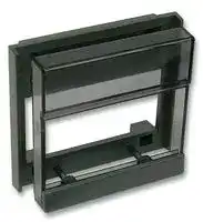
301.610
Panel Adapter, 3200 Series PID Controllers, 1/16 DIN
⚠️ Reference pricing provided. In case of supply shortages, we will connect you with our trusted procurement partners to ensure your project's continuity.
- Manufacturer: CAL CONTROLS
- Product type: Controller Accessories
- Current Rating:-; Product Range:-; Accessory Type:Panel Adapter; For Use With:PID Controllers
- Product Range: -
- Current Rating: -
| Delivery and price | |
|---|---|
| Units per pack | 25 |
| Price | 7.19 € |
| Current stock | 10+ |
| Lead time | 30 days |
Datasheet

~

To environment and pollution degree 2. avoid possible hazards accessible conductive parts of final installation should be protectively earthed in accordanceOutput wiring withshould EN61010be within for Classa grounded1 equipment.cabinet. Sensor sheaths should be bonded to ground or not be accessible. Live parts should not be accessible without use of a tool. Itthatis the thisresponsibility equipment’sofcompliancethe installationto EN61010engineeris notto ensure impaired when fitted to the final installation and to use equipment as specified in this manual, failure to do so may impair the protection provided. Ensure the installation is in compliance with appropriate wiring regulations

## 1.2 CONFIGURATION

Allof thefunctionsinstallingareengineerfront keytoselectable, ensure thatit theis the configurationresponsibility is safe. Use the program lock to protect critical functions from tampering 1.3 ULTIMATE SAFETY ALARMS

Normal safety advice: Do not use SP2 as the sole alarm equipmentwhere personal failureinjury or damage may be caused by WARRANTY

.

**==> picture [13 x 94] intentionally omitted <==**

**----- Start of picture text -----**<br>
3,<br>4<br>_<br>**----- End of picture text -----**<br>


**==> picture [116 x 211] intentionally omitted <==**

**----- Start of picture text -----**<br>
2. Single level navigation<br><_ —<br>3.<br> View/Change Option<br>View ie<br>OptionFunction/‘i ibSi—in|—<br>auiotne | = Et<br>Option value ig VO)<br>Option value meal<br>(or<br>Release: * w check) BScorrect<br>**----- End of picture text -----**<br>


**==> picture [111 x 146] intentionally omitted <==**

**----- Start of picture text -----**<br>
2. Select input sensor<br>ress an *<br>Me| — ee<br>Press A GNmh<br>eo<br>corectly fac i<br>selected PoPSiG 4|iewm |<br>3. . Selectselec  °C/°F<br>Pr<br>Press once | Sie—FNM<br>**----- End of picture text -----**<br>


Slide the panel clamp on the controller and press it firmly against the panel Note: To remove the panel clamp the two side 5. levers should be pressed in Refit the connector if removed. To further secure 6. the connector slide the green lock as shown After installation remove protective front window 7. label Cleaning — wipe down front with damp cloth (water only) 4.1 3200 CONTROLLER PROTECTION RATING The 3200 controller front of panel assembly is rated NEMA 4X/IP66 provided: - The panel is smooth, and cutout accurate — The panel clamp is pressed firmly against the panel, ensuring that the clamp springs are fully compressed 4.2 MULTIPLE 3200 INSTALLATIONS

## 5.2 Output devices (two)

## 5.3 Output device allocation

## 5.4 Wiring the 8 way connector

- 6 INITIAL SETTING UP 6.1 OVERVIEW Meet— ee initial power-up to accurately ME SORT

- 6.1.1 Details required for initial configuration 1.2 The temperaturepaleee| ork sensorTD/Ptbeingee used: 3. Choice of controller output device for the main setpoint SP1, either: orThethesolidminiature state relay drivepower relay| a

- 4, Any additional controller functions, eg, SP2 Alarms, may be selected now or later

6.1.2 Set the temperature required

      - The controller is now operational with factory

- 6.1.3 To tune the 3200 precisely to the application:

   - —- Run the Autotune program see7 | This automatically adjusts the PID control parameters to the characteristics of the

   - - applicationOrenter PID values manually Where the optimum values are already known

6.2 INITIAL CONFIGURATION 6.2.1 Power up EEEEA Self test sequence (and CGVa brief display blanking) ls teh ere es = is selected and that one is | Sar#S—-¥—[4)][ val] required

**==> picture [217 x 173] intentionally omitted <==**

**----- Start of picture text -----**<br>
6.2.2 To enter the input;  sensor type<br>pemonhen ecb<br>- Press & to select the sensor e.g. K | Prk VSR<br>Press Ww to reverse indexing<br>Input sensor options (also see 16.2.10)<br>= - -<br>Boyee f]) N Jee A<br>E Ee c R Ee<br>J Le f S Ee 5<br>K re oH - ie &<br>L b ot<br>Resistance. RID2Rib<br>thermometer — [PtIOO|<br>**----- End of picture text -----**<br>


6.2.4

- Setnormal the usualload setpointconditions temperature and use aft, 7.1.2 To enter program modes =

**==> picture [104 x 12] intentionally omitted <==**

**----- Start of picture text -----**<br>
7.1.3 To selectitunE/on|<br>**----- End of picture text -----**<br>


- Lee.2.2

## 8.1.1 Definitions

##

8.1.3 Hintsupdatedwhen using program

8.2.4 To displaythes runctonsthe current Option value for

8.2.5 Autotune Option values/ EEG

will cause oscillation Too short a setting will cause unnecessary to an electro-mechanical switching device

- 9.1

## 9.1.1

-

-

## 9.1.2

- 9.1.3 Manually pre-select any cycle-time between

9.4.2 Index to

9.4.3 To view calculated optimum

saad at aaeeaactle suitable cycletime

3. If theSP2.b], factoryseeset10.52.0° C/3.6°F hysteresis is unsuitable, change in Set [CYC.2| ON/OFF (factory setting)

4, Adjust SP2 setpoint in (to set y° in 10.4) 5. Exit program mode — SP2 is now operational as an alarm

10.2 TO CONFIGURE SP2 AS A PROPORTIONAL 1. CONTROL OUTPUT Select the main operating mode in [SP2.A],

2. see 10.4 Select SP2 proportional band in [bnd.2] and SP2 cycle-time in |CYC.2]

3. Adjust SP2 setpoint in [SEt.2] (to set y° in 10.4) 4. Exit program mode -— $P2 is now operational as a contro! output with time proportioning control action

10.3 SP2 IN COOL STRATEGY For full instructions see separate data:

When selected the alarm output and indicator latch, When the alarm condition has been cleared, momentarily press W4 together to reset

## 10.5.2

Whenon power selected, up. Thein any alarm alarmis enabledmode, only prevents when an the alarm process temperature reaches setpoint alarmExample: Sequence alarm used with deviation low - [avo]

## W401 [hi.sC] tullecale and

2. -Factory pial=settings:sensor includingmaximum |LoSC]negative = mata“ to set below

3. [hi.SC] may not be adjusted: below

11.1.2 Example: Setpoint limited to 400° - 600°C ai Ses sensor maximum Ihi.sG factory setting ° 7 600°C hi.SC} reduced to 600°C fp ~ max safe temperature setpoint range

**==> picture [165 x 73] intentionally omitted <==**

**----- Start of picture text -----**<br>
operationDuring monitoor r emaining eitherin program return tomode normal<br>To view monitor readings: Index to<br>Release ¥ or « ie<br>**----- End of picture text -----**<br>


**==> picture [104 x 76] intentionally omitted <==**

**----- Start of picture text -----**<br>
Press and hold *<br>Displays:  variance (06°)°<br>HoldPress * pressed4 once<br>**----- End of picture text -----**<br>


**==> picture [219 x 202] intentionally omitted <==**

**----- Start of picture text -----**<br>
| one wayee only fievela<br>: eT FEI<br>|<br>14.(4.1) PES | = x<br>Derivative sensitivity<br>14.(4.2) FR irl] - 21)<br>Display sensitivity<br>[tJ = Direct display of input<br>= Maximum [32] = Minimum sensitivity<br>14.(4.3)<br> Ene<br>Disable SP2 Alarm annunciator<br>Select [on] to disable<br>14,(4.4) Pro G | STAY<br>Program mode auto-exit switch<br>**----- End of picture text -----**<br>


15.7 Autotune tuning data and limits

~— se a7 Vv Too(slowshort warm up and response, junder 16(1.5) EG SP! Derivative Tunes warm normal when derivative (neler IAC —_——_ Too small (overshoots)

16(2.2) EEN (oF F\(7)% (Not in SP] manual percentage power control For manual control should a sensor fail Record typical values beforehand 16(2.3) Set SP1iapower limit-[0]%percentage duty cycle Limits max SP] heating power during warm up and in proportional band 16(2.4) SetEESP2 percent power[0]%limitduty(cooling) cycle SP2 OPERATING MODES, see 10 16(2.5) EEE Main: SP2 operating mode ad 4 16(2.6) REESE [none] [ich SubsidiaryNon-linear $P2 mode: latch/sequence cool proportional band INPUT SELECTION AND RANGING 16(2.7) eee Cfo? Te

required to change 16(3.2) 15 Ped,

## TECHNICAL FUNCTIONS

## 16(3.3) lburn| Sensor burn-out/break protection Caution: Setting affects fail safe state SP1 SP2 Upscale Upscale !1u.2d| UpscaleDownscale DownscaleDownscale |1d.2u| Downscale Upscale 16(3.4) IEESEEET seiect output modes: Direct/Reverse Caution: Setting affects fail safe state

> Standards: DIN 43760 (OO2 O° C/138.52 1OO °C Pt) ; Bulb ; current: O.2mA maximum Linear process inputs: mV range: -1O to SOmV See “PIM Process Interface Module” for additional input/output options Applleablé fo all abuts’ , pplicable fo all inputs: SM = sensor maximum Calibration accuracy: +O0.25%SM +1°C Sampling frequency: Input 1OHz, CJC 2 sec eenee oAaynode Negligible effect up to Series mode sairejection:sae z60dB, 50-6OHz Temperature coefficient: 150 ppm/ °C SM Reference conditions: 22°C +2°C, rated voltage, after 15 minutes settling time OUTPUT DEVICES (Standard), see 5.3 - $Sd: Solid state relay drive: To switch tl

ao¥ a a ns i aeelfelee ee eeee i imuacn|eaieareireves | | eS ry ee Perez ee | ee EE | P20 | Loeb | ee a oe ee as | inte | eee
Updated at April 29, 2026
About Novapart
Novapart is a B2B electronic component broker specialising in stock shortages and cost reduction. We source hard-to-find parts and identify compliant alternatives across a catalogue of 410,000+ components from 500+ manufacturers.
Learn more →Stock Shortage Specialist
When a component is unavailable, discontinued or has an unacceptable lead time, we tap into our network of vetted European and Asian distributors to source what you need — without compromising on quality or traceability.
Request a quote →Compliant Alternatives
We identify pin-to-pin, electrically equivalent substitutes that meet the same certifications (RoHS, AEC-Q100, REACH) as your original specification — validated against datasheets, not just part numbers. Often at a lower cost.
BOM Analysis service →