


2CDS253001R0501
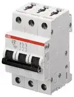
Thermal Magnetic Circuit Breaker, System Pro M Compact S200, 50 A, 3 Pole, 277 V, DIN Rail
- Manufacturer: ABB
- Product type: Thermal Magnetic Circuit Breakers
- Product Range:System Pro M Compact S200 Series; Current Rating:50A; No. of Poles:3 Pole; Voltage Rating V DC:-; Voltage Rating VAC:277VAC; Circuit Breaker Mounting:DIN Rail
- SVHC: To Be Advised
- No. of Poles: 3 Pole
- Product Range: System Pro M Compact S200
- Current Rating: 50A
- Voltage Rating VAC: 277V
- Voltage Rating VDC: -
- Circuit Breaker Mounting: DIN Rail
| Delivery and price | |
|---|---|
| Units per pack | 20 |
| Price | 103.14 € |
| Current stock | 10+ |
| Lead time | 9 days |
**Data Sheet**

## System pro M compact[®] Miniature Circuit Breaker S 200/S 200 M

**==> picture [460 x 75] intentionally omitted <==**

**----- Start of picture text -----**<br>
&’<br>@<br>€ 2CDC021023S0012 « 8 ¢ 0 2CDC021038S0012<br>**----- End of picture text -----**<br>


The miniature circuit breakers of the System pro M compact[®  ] series S 200 and S 200 M provide state-of-the-art safety and comfort. They stand out due to their high performance and the wide range of accessories and approvals.

## Features

- −Clear contact position indication in red/green (“real CPI”)

- −Unique, patented twin terminal with captive screws and an increased opening for cables up to max. 35 mm[2] , finger-proof (IP20)

- −Busbar slot in the back for best visibility during installation

- −High performance at an increased rated voltage for marine and industrial applications: 10 kA/15 kA at Un = 440 V AC acc. to IEC/EN 60947-2

- −Individual product identification code

- −Approved acc. to IEC/EN 60898-1, IEC/EN 60947-2 and UL 1077/CSA 22.2 No. 235 for global use

Miniature Circuit Breaker S 200/S 200 M Technical data

**==> picture [518 x 647] intentionally omitted <==**

**----- Start of picture text -----**<br>
S 200 S 200 M<br>General Data<br>Standards   IEC/EN 60898-1, IEC/EN 60947-2 IEC/EN 60898-1, IEC/EN 60947-2<br>UL 1077 UL 1077, CSA 22.2 No. 235<br>Poles 1P, 2P, 3P, 4P, 1P+N, 3P+N<br>Tripping Characteristics B, C, D, K, Z<br>Rated current In 0.5 up to 63 A<br>Rated insulation voltage Ui 250 V AC (phase to ground), 500 V AC (phase to phase)<br>Rated frequency   50/60 Hz<br>Overvoltage Category   III<br>Pollution Degree   3<br>IEC/EN 60898-1<br>Rated operational voltage Un 1P: 230/400 V AC; 1P+N: 230 V AC; 2P, 3P, 4P: 400 V AC; 3P+N: 400 V AC<br>Power frequency recovery voltage Umax 1P: 253 V AC; 1P+N: 253 V AC; 2P, 3P, 4P: 440 V AC; 3P+N: 440 V AC;<br>1P: 72 V DC; 2P: 125 V DC<br>Min. operating voltage   12 V AC, 12 V DC<br>Rated short-circuit capacity Icn 6 kA  10 kA<br>Energy limiting class (B, C up to 40 A) 3<br>Rated impulse withstand voltage Uimp (1.2/50 µs)   4 kV (test voltage 6.2 kV at sea level, 5 kV at 2,000 m)<br>Dielectric test voltage   2.0 kV (50/60 Hz, 1 min)<br>Reference temperature for tripping characteristics B, C, D: 30 °C<br>Electrical endurance   In < 32 A: 20,000 ops. (AC), 1,000 ops. (DC); one cycle 2 s - ON, 13 s - OFF<br>In ≥ 32 A: 10,000 ops. (AC), 1,000 ops. (DC); one cycle 2 s - ON, 28 s - OFF<br>IEC/EN 60947-2<br>Rated operational voltage Ue 1P: 230 V AC; 1P+N: 230 V AC; 2P, 3P, 4P: 440 V AC; 3P+N: 440 V AC<br>Power frequency recovery voltage Umax 1P: 253 V AC; 1P+N: 253 V AC; 2P, 3P,4P: 462 V AC; 3P+N: 462 V AC;<br>1P: 72 V DC; 2P: 125 V DC<br>Min. operating voltage  12 V AC, 12 V DC<br>Rated ultimate short-circuit breaking capacity Icu 10 kA 15 kA<br>Rated service short-circuit breaking capacity Ics 7.5 kA ≤ 40 A:   11.2 kA<br> 50, 63 A:    7.5 kA<br>Rated impulse withstand voltage Uimp (1.2/50 µs)   4 kV (test voltage 6.2 kV at sea level, 5 kV at 2,000 m)<br>Dielectric test voltage   2.0 kV (50/60 Hz, 1 min)<br>Reference temperature for tripping characteristics B, C, D:  55 °C;   K, Z:  20 °C<br>Electrical endurance   In < 32 A: 20,000 ops. (AC), 1,000 ops. (DC); one cycle 2 s - ON, 13 s - OFF<br>In ≥ 32 A: 10,000 ops. (AC), 1,000 ops. (DC); one cycle 2 s - ON, 28 s - OFF<br>Data acc. to UL/CSA<br>Rated voltage 480Y / 277 V AC<br>Rated interrupting capacity 6 kA<br>Application Suppl. prot. for general use. Application Codes: TC2, OL0, SC: U1<br>Reference temperature for tripping characteristic B, C, D, K, Z: 25 °C<br>Electrical endurance   6,000 ops. (AC), 6,000 ops. (DC); one cycle 1 s - ON, 9 s - OFF<br>Mechanical data<br>Housing Insulation group II, RAL 7035   Insulation group I, RAL 7035<br>Toggle   Insulation group II, black, sealable<br>Contact position indication   Marking on toggle (I ON/0 OFF), Real CPI (red ON/green OFF)<br>Protection degree acc. to EN 60529   IP20*, IP40 in enclosure with cover<br>Mechanical endurance 20,000 ops.<br>Shock resistance acc. to IEC/EN 60068-2-27 25 g, 3 shocks, 11 ms<br>Vibration resistance acc. to IEC/EN 60068-2-6 5 g, 20 cycles at 5…150…5 Hz with load 0.8 In<br>Environmental conditions acc. to IEC/EN 60068-2-30 28 cycles with 55 °C/90-96 % and 25 °C/95-100 %<br>Ambient temperature -25 ... +55 °C<br>Storage temperature   -40 ... +70 °C<br>**----- End of picture text -----**<br>


* Also fulfilling the requirements acc. to the protection degree IPXXB

2 - 2CDC002157D0201

## Miniature Circuit Breaker S 200/S 200 M Technical data and tripping characteristics

**==> picture [518 x 281] intentionally omitted <==**

**----- Start of picture text -----**<br>
S 200 S 200 M<br>Installation<br>Terminal Failsafe bi-directional cylinder-lift terminal<br>Cross-section of conductors (top/bottom) 35 mm [2]  / 35 mm [2]<br>18 – 4 AWG<br>Cross-section of busbars (top/bottom) 10 mm [2]  / 10 mm [2]<br>18 – 8 AWG<br>Torque 2.8 Nm<br>25 in-Ibs.<br>Screwdriver   No. 2 Pozidrive<br>Mounting On DIN rail 35 mm acc. to EN 60715 by fast clip<br>Mounting position   any<br>Supply  optional<br>Dimensions and weight<br>Mounting dimensions acc. to DIN 43880 Mounting dimension 1<br>Pole dimensions (H x D x W) 85 x 69 x 17.5<br>Pole weight approx. 125 g<br>Combination with auxiliary elements<br>Auxiliary contact Yes<br>Signal/auxiliary contact Yes<br>Shunt trip Yes<br>Undervoltage release Yes<br>Motor Operating Device Yes<br>**----- End of picture text -----**<br>


## Tripping characteristics

|Acc. to|Tripping<br>characte-<br>ristics|Rated<br>current<br>In|Thermal release1)<br>Currents:<br>conventional<br>non-tripping<br>current<br>I1<br>conventional<br>tripping<br>current<br>I2<br>Tripping<br>time|Thermal release1)<br>Currents:<br>conventional<br>non-tripping<br>current<br>I1<br>conventional<br>tripping<br>current<br>I2<br>Tripping<br>time|Thermal release1)<br>Currents:<br>conventional<br>non-tripping<br>current<br>I1<br>conventional<br>tripping<br>current<br>I2<br>Tripping<br>time|Electromagnetic release2)<br>Range of<br>instantaneous<br>tripping<br>Tripping time|Electromagnetic release2)<br>Range of<br>instantaneous<br>tripping<br>Tripping time|Electromagnetic release2)<br>Range of<br>instantaneous<br>tripping<br>Tripping time|
|---|---|---|---|---|---|---|---|---|
|IEC/EN 60898-1|B|6 to 63 A|1.13 · In|1.45 · In|> 1 h<br>< 1 h|3 · In|5 · In|0.1 ... 45 s (In≤ 32 A)/0.1 ... 90 s (In> 32 A)<br>< 0.1 s|
||C|0.5 to 63 A|1.13 · In|1.45 · In|> 1 h<br>< 1 h 3)|5 · In|10 · In|0.1 ... 15 s (In≤ 32 A)/0.1 ... 30 s (In> 32 A)<br>< 0.1 s|
||D|0.5 to 63 A|1.13 · In|1.45 · In|> 1 h<br>< 1 h 3)|10 · In|20 · In|0.1 ... 4 s (In≤ 32 A)/0.1 ... 8 s (In> 32 A)<br>< 0.1 s|
|IEC/EN 60947-2|K|0.5 to 63 A|1.05 · In|1.2 · In|> 1 h<br>< 1 h|not applicable|||
||||1.05 · In|1.2 · In|> 2 h<br>< 1 h 3)|10 · In|14 · In|> 0.2 s<br>< 0.2 s|
||Z|0.5 to 63 A|1.05 · In|1.2 · In|> 1 h<br>< 1 h|not applicable|||
||||1.05 · In|1.2 · In|> 2 h<br>< 1 h 3)|2 · In|3 · In|> 0.2 s<br>< 0.2 s|


- 1)  The thermal releases are calibrated to a nominal reference ambient temperature; for B, C, D the reference value is 30 °C, for K and Z the reference value is 20 °C. In the case of higher ambient temperatures, the current values fall by approx. 6 % for each 10 K temperature rise.

- 2)  The indicated tripping values of electromagnetic tripping devices apply to a frequency of 50/60 Hz. The thermal release operates independent of frequency.

- 3)  As from operating temperature (after I1 > 1h or, as applicable, 2h)

2CDC002157D0201 - 3

## Miniature Circuit Breaker S 200/S 200 M Tripping characteristics

**==> picture [516 x 609] intentionally omitted <==**

**----- Start of picture text -----**<br>
B characteristic C characteristic D characteristic<br>K characteristic Z characteristic<br>2CDC022006F0211 2CDC022008F0211 2CDC022108F0209<br>2CDC022010F0211 2CDC022060F0211<br>**----- End of picture text -----**<br>


4 - 2CDC002157D0201

## Miniature Circuit Breaker S 200/S 200 M Derating

For installations of miniature circuit breakers at other temperatures than the reference value and installations of several miniature circuit breakers directly side by side, derating factors have to be considered.

## Deviating ambient temperature

The rated value of the current of a miniature circuit breaker refers to a reference ambient temperature of 30 °C for circuit breakers with the characteristics B, C and D and 20 °C for circuit breakers with the characteristics K and Z. The following table contains the derating of the load capability at ambient temperatures from -40 °C to 70 °C for the characteristics B, C, D, K and Z.

**==> picture [518 x 422] intentionally omitted <==**

**----- Start of picture text -----**<br>
Tripping Rated Maximum operating current at ambient temperature T<br>charac- current<br>teristics In<br>A - 40 °C - 30 °C - 20 °C - 10 °C   0 °C 10 °C 20 °C 30 °C 40 °C 50 °C 60 °C 70 °C<br>B, C, D 0.5 0.67 0.65 0.62 0.60 0.58 0.55 0.53 0.50 0.47 0.44 0.41 0.37<br>1.0 1.33 1.29 1.25 1.20 1.15 1.11 1.05 1.00 0.94 0.88 0.82 0.75<br>1.6 2.13 2.07 2.00 1.92 1.85 1.77 1.69 1.60 1.51 1.41 1.31 1.19<br>2.0 2.67 2.58 2.49 2.40 2.31 2.21 2.11 2.00 1.89 1.76 1.63 1.49<br>3.0 4.0 3.9 3.7 3.6 3.5 3.3 3.2 3.0 2.8 2.6 2.4 2.2<br>4.0 5.3 5.2 5.0 4.8 4.6 4.4 4.2 4.0 3.8 3.5 3.3 3.0<br>6.0 8.0 7.7 7.5 7.2 6.9 6.6 6.3 6.0 5.7 5.3 4.9 4.5<br>8.0 10.7 10.3 10.0 9.6 9.2 8.8 8.4 8.0 7.5 7.1 6.5 6.0<br>10.0 13.3 12.9 12.5 12.0 11.5 11.1 10.5 10.0 9.4 8.8 8.2 7.5<br>13.0 17.3 16.8 16.2 15.6 15.0 14.4 13.7 13.0 12.3 11.5 10.6 9.7<br>16.0 21.3 20.7 20.0 19.2 18.5 17.7 16.9 16.0 15.1 14.1 13.1 11.9<br>20.0 26.7 25.8 24.9 24.0 23.1 22.1 21.1 20.0 18.9 17.6 16.3 14.9<br>25.0 33.3 32.3 31.2 30.0 28.9 27.6 26.4 25.0 23.6 22.0 20.4 18.6<br>32.0 42.7 41.3 39.9 38.5 37.0 35.4 33.7 32.0 30.2 28.2 26.1 23.9<br>40.0 53.3 51.6 49.9 48.1 46.2 44.2 42.2 40.0 37.7 35.3 32.7 29.8<br>50.0 66.7 64.5 62.4 60.1 57.7 55.3 52.7 50.0 47.1 44.1 40.8 37.3<br>63.0 84.0 81.3 78.6 75.7 72.7 69.6 66.4 63.0 59.4 55.6 51.4 47.0<br>K, Z 0.5 0.66 0.64 0.61 0.59 0.56 0.53 0.50 0.47 0.43 0.40 0.35 0.31<br>1.0 1.32 1.27 1.22 1.17 1.12 1.06 1.00 0.94 0.87 0.79 0.71 0.61<br>1.6 2.12 2.04 1.96 1.88 1.79 1.70 1.60 1.50 1.39 1.26 1.13 0.98<br>2.0 2.65 2.55 2.45 2.35 2.24 2.12 2.00 1.87 1.73 1.58 1.41 1.22<br>3.0 4.0 3.8 3.7 3.5 3.4 3.2 3.0 2.8 2.6 2.4 2.1 1.8<br>4.0 5.3 5.1 4.9 4.7 4.5 4.2 4.0 3.7 3.5 3.2 2.8 2.4<br>6.0 7.9 7.6 7.3 7.0 6.7 6.4 6.0 5.6 5.2 4.7 4.2 3.7<br>8.0 10.8  10.2 9.8 9.4 8.9 8.5 8.0 7.5 6.9 6.3 5.7 4.9<br>10.0 13.2 12.7 12.2 11.7 11.2 10.6 10.0 9.4 8.7 7.9 7.1 6.1<br>13.0 17.2 16.6 15.9 15.2 14.5 13.8 13.0 12.2 11.3 10.3 9.2 8.0<br>16.0 21.2 20.4 19.6 18.8 17.9 17.0 16.0 15.0 13.9 12.6 11.3  9.8<br>20.0 26.5 25.5 24.5 23.5 22.4 21.2 20.0 18.7 17.3 15.8 14.1 12.2<br>25.0 33.1 31.9 30.6 29.3 28.0 26.5 25.0 23.4 21.7 19.8 17.7 15.3<br>32.0 42.3 40.8 39.2 37.5 35.8 33.9 32.0 29.9 27.7 25.3 22.6 19.6<br>40.0 52.9 51.0 49.0 46.9 44.7 42.4 40.0 37.4 34.6 31.6 28.3 24.5<br>50.0 66.1 63.7 61.2 58.6 55.9 53.0 50.0 46.8 43.3 39.5 35.4 30.6<br>63.0 83.3 80.3 77.2 73.9 70.4 66.8 63.0 58.9 54.6 49.8 44.5 38.6<br>**----- End of picture text -----**<br>


## Influence of adjacent devices

## Example

If several miniature circuit breakers are installed directly side by side with high load on all poles, a correction factor has to be applied to the rated current (see table). If distance pieces are used, the factor is not to be considered.

S201-C16 at T = 40 °C

**==> picture [517 x 123] intentionally omitted <==**

**----- Start of picture text -----**<br>
by side with high load on all poles, a correction factor has to  Conditions      Values to use Calculation Result<br>be applied to the rated current (see table). If distance pieces  of use<br>are used, the factor is not to be considered. Load at ambient  In (40 °C),  15.1 A x 0.75 In = 11.33 A<br>temperature  Factor F<br>40 °C with<br>No. of adjacent devices Factor F<br>8 adjacent<br>1 1<br>devices<br>2, 3 0.9<br>4, 5 0.8<br>≥ 6 0.75<br>**----- End of picture text -----**<br>


2CDC002157D0201 - 5

## Miniature Circuit Breaker S 200/S 200 M Accessories and dimensional drawing

## Accessory overview

H Auxiliary contact S2C-H6R (change-over contact) H-R Auxiliary contact S2C-H6-...R S/H Signal/Auxiliary contact S2C-S/H6R S/H (H) Signal/Auxiliary contact used as auxiliary contact S2C-S/H6R ST Shunt trip S2C-A... UR Undervoltage release S2C-UA OR Overvoltage release S2C-OVP

H-L Auxiliary contact S2C-H...L H-BF Auxiliary contact for bottom fitting S2C-H01 (1 per pole) S2C-H10 BP Mechanical tripping device S2C-BP NT Neutral disconnector S2C-Nt MOD-S* Motor operating device S2C-CM DDA 200 RCD-block DDA 20...

*  In case of using S 200/S 200 M coupled with DDA 200, MOD-S does not operate in case of earth-leakage fault.

## Dimensional drawing

6 - 2CDC002157D0201

## Contact us

## ABB STOTZ-KONTAKT GmbH

Eppelheimer Straße 82 69123 Heidelberg, Germany Phone: +49 (0) 6221 7 01-0 Fax: +49 (0) 6221 7 01-13 25 E-Mail: info.desto@de.abb.com

You can find the address of your local sales organization on the ABB home page http://www.abb.com/contacts -> Low Voltage Products and Systems

## Note:

We reserve the right to make technical changes or modify the contents of this document without prior notice. With regard to purchase orders, the agreed particulars shall prevail. ABB AG does not accept any responsibility whatsoever for potential errors or possible lack of information in this document.

We reserve all rights in this document and in the subject matter and illustrations contained therein. Any reproduction, disclosure to third parties or utilization of its contents – in whole or in parts – is forbidden without prior written consent of ABB AG.

Copyright© 2012 ABB All rights reserved
Updated at June 7, 2026
ABB is a global leader in power and automation technologies, recognized for delivering innovative solutions that improve performance while minimizing environmental impact. Serving a diverse range of sectors including industrial processing, OEM, and building services, ABB provides highly reliable components designed to meet the rigorous demands of modern electrical systems. The company is particularly renowned for its advanced circuit protection solutions. This includes a comprehensive selection of thermal magnetic circuit breakers, alongside specialized RCBO, RCD, GFCI, and AFDD circuit breakers. These foundational safety components are supported by a wide array of high-quality fuse holders and circuit breaker accessories, ensuring complete protection for complex industrial and commercial installations. Beyond circuit protection, ABB excels in automation and process control. Their offering features sophisticated visual signal indicator units, industrial switch accessories, and panel instrumentation designed for intuitive system monitoring. Additionally, ABB manufactures a robust range of power relays, safety relays, and AC/DC converters, providing engineers with the critical building blocks needed for efficient, secure, and reliable control panels.
About Novapart
Novapart is a B2B electronic component broker specialising in stock shortages and cost reduction. We source hard-to-find parts and identify compliant alternatives across a catalogue of 410,000+ components from 500+ manufacturers.
Learn more →Stock Shortage Specialist
When a component is unavailable, discontinued or has an unacceptable lead time, we tap into our network of vetted European and Asian distributors to source what you need — without compromising on quality or traceability.
Request a quote →Compliant Alternatives
We identify pin-to-pin, electrically equivalent substitutes that meet the same certifications (RoHS, AEC-Q100, REACH) as your original specification — validated against datasheets, not just part numbers. Often at a lower cost.
BOM Analysis service →