


2981554
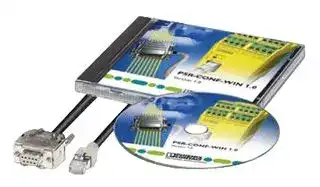
Relay Accessory, Software, PSR-RSM4
- Manufacturer: PHOENIX CONTACT
- Product type: Other Relay Accessories
- Accessory Type:Software; For Use With:PSR-RSM4; Product Range:-; SVHC:No SVHC (15-Jan-2018)
- SVHC: No SVHC (21-Jan-2025)
- For Use With: PSR-RSM4
- Product Range: -
- Accessory Type: Software
| Delivery and price | |
|---|---|
| Units per pack | 1 |
| Price | 107.55 € |
| Current stock | 10+ |
| Lead time | 30 days |
## **INTERFACE**

## **User Manual**

**UM EN PSR-CONF-WIN Order No.: 2888107**

PSR Configuration Software

09/2005

## **INTERFACE**

## **User Manual**

## **PSR Configuration Software**

Designation: UM EN PSR-CONF-WIN

Revision: 00 Order No.: 2888107

This manual is valid for:

Designation Version Order No. PSR-CONF-WIN1.0 1.0 2981554

PHOENIX CONTACT

**102671_00_en**

**PSR-CONF-WIN**

## Please Observe the Following Notes

In order to guarantee the safe use of the product described, please read this manual carefully. The following notes give you information on how to use this manual.

## **Qualifications of the User Group**

The product usage described in this manual is exclusively aimed at qualified application programmers and software engineers who are familiar with the safety concepts of automation technology, as well as the valid national standards. Phoenix Contact assumes no liability for damage to any products resulting from disregard of information contained in this manual.

## **Explanation of Symbols Used**

**==> picture [36 x 110] intentionally omitted <==**

The _attention_ symbol refers to an operating procedure which, if not carefully followed, could result in damage to equipment or personal injury.

The _note_ symbol informs you of conditions that must strictly be observed to achieve errorfree operation. It also gives you tips and advice on hardware and software optimization to save you extra work.

The _text_ symbol refers you to detailed sources of information (manuals, data sheets, literature, etc.) on the subject matter, product, etc. This text also provides helpful information for the orientation in the manual.

## **We Are Interested in Your Opinion**

We are constantly striving to improve the quality of our documents.

Should you have any suggestions or recommendations for improving the contents and layout of our documents, please send us your comments.

PHOENIX CONTACT GmbH & Co. KG Documentation Services 32823 Blomberg GERMANY

Phone +49 - (0) 52 35 - 3-00 Telefax +49 - (0) 52 35 - 3-4 20 21 E-Mail tecdoc@phoenixcontact.com

PHOENIX CONTACT

**102671_00_en**

**PSR-CONF-WIN**

## **General Terms and Conditions of Use for Technical Documentation**

Phoenix Contact GmbH & Co. KG reserves the right to alter, correct, and/or improve the technical documentation and the products described in the technical documentation at its own discretion and without giving any notice.

The receipt of technical documentation (in particular data sheets, installation instructions, manuals, etc.) does not constitute any further duty on the part of Phoenix Contact GmbH & Co. KG to furnish information on alterations to products and/or technical documentation. Any other agreement shall only apply if expressly confirmed in writing by Phoenix Contact GmbH & Co. KG. Please note that the supplied documentation is a product-specific documentation only.

Although Phoenix Contact GmbH & Co. KG makes every effort to ensure that the information content is accurate, up-to-date and state-of-the-art, technical inaccuracies and/or printing errors in the information cannot be ruled out. Phoenix Contact GmbH & Co. KG does not offer any guarantees as to the reliability, accuracy or completeness of the information appearing on the Website. Phoenix Contact GmbH & Co. KG accepts no liability or responsibility for errors or omissions in the content of the technical documentation (in particular data sheets, installation instructions, manuals, etc.).

As far as is permissible by applicable jurisdiction, no guarantee or claim for liability for defects whatsoever shall be granted in conjunction with the information available in the technical documentation, whether expressly mentioned or implied. This information does not include any guarantees on quality, does not describe any fair marketable quality and does not make any claims as to quality guarantees or guarantees on the suitability for a special purpose. Phoenix Contact GmbH & Co. KG reserves the right to alter, correct, and/ or improve the information and the products described in the information at its own discretion and without giving any notice.

PHOENIX CONTACT

**102671_00_en**

## **PSR-CONF-WIN**

## **Statement of Legal Authority**

This manual, including all illustrations contained herein, is copyright protected. This manual is to be used for its intended purpose only, all other usage is prohibited. Reproduction, translation and public disclosure, as well as electronic and photographic archiving and modification require written consent by Phoenix Contact. Violators are liable for damages.

Phoenix Contact reserves the right to make any technical changes that serve the purpose of technical progress.

Windows 3.x, Windows 95, Windows 98, Windows NT, Windows 2000, Windows XP and MS-DOS are trademarks of Microsoft Corporation.

Genesis for Windows is a trademark of ICONICS Inc.

All other product names used are trademarks of the respective organizations.

## **Internet**

You will find current information on products from Phoenix Contact on the Internet at: **www.phoenixcontact.com** .

All the latest Phoenix Contact documentation can be found on the Internet at:

**www.download.phoenixcontact.com** .

PHOENIX CONTACT

**102671_00_en**

## Table of Contents

||Table of Contents|Table of Contents|
|---|---|---|
|1|PSR-RSM Speed Monitor........................................................................................................1-1||
||1.1|Short Description................................................................................................1-1|
||1.2|Function .............................................................................................................1-1|
|||1.2.1<br>Function Diagram ...............................................................................1-1|
|||1.2.2<br>Function ..............................................................................................1-2|
||1.3|Application..........................................................................................................1-3|
|||1.3.1<br>Safety Circuits ....................................................................................1-3|
|||1.3.2<br>Requirements for Speed Monitoring ...................................................1-3|
|||1.3.3<br>Required Equipment on the Machine .................................................1-4|
||1.4|Ordering Data.....................................................................................................1-4|
||1.5|Technical Data ...................................................................................................1-5|
|2|Hardware Installation...............................................................................................................2-1||
||2.1|Mounting ............................................................................................................2-1|
||2.2|Operating Elements ...........................................................................................2-2|
||2.3|LEDs ..................................................................................................................2-2|
||2.4|Electrical Connections........................................................................................2-3|
|||2.4.1<br>RJ45 Programming and Encoder Connection ....................................2-3|
|||2.4.2<br>Initiator Connection .............................................................................2-4|
|||2.4.3<br>Supply Voltage ...................................................................................2-5|
|||2.4.4<br>Start Circuit Connection ......................................................................2-5|
|||2.4.5<br>Operating Mode Selection ..................................................................2-6|
|||2.4.6<br>Switching Outputs ...............................................................................2-7|
|||2.4.7<br>Alarm Outputs .....................................................................................2-8|
||2.5|Error Detection ...................................................................................................2-9|
|||2.5.1<br>Initiator Errors, Data Errors .................................................................2-9|
|||2.5.2<br>Encoder Errors ...................................................................................2-9|
|||2.5.3<br>Device Errors ......................................................................................2-9|
|3|Software Installation ................................................................................................................3-1||
||3.1|System Requirements........................................................................................3-1|
||3.2|Installation Instructions.......................................................................................3-1|
||3.3|Operation ...........................................................................................................3-4|
||3.4|Parameterization - Toolbar.................................................................................3-5|
|||3.4.1<br>New ....................................................................................................3-5|
|||3.4.2<br>Open ...................................................................................................3-5|
|||3.4.3<br>Save ...................................................................................................3-5|
|||3.4.4<br>Print ....................................................................................................3-6|
|||3.4.5<br>Upload Data ........................................................................................3-6|
|||3.4.6<br>Download Data ...................................................................................3-6|
|||3.4.7<br>Program Info .......................................................................................3-6|
|||3.4.8<br>History  ...............................................................................................3-6|
|||3.4.9<br>Technical Documentation ...................................................................3-7|


PHOENIX CONTACT **i**

**102671_00_en**

## **PSR-CONF-WIN**

|||3.4.10|COM Port  ...........................................................................................3-7|
|---|---|---|---|
|||3.4.11|Change Password ..............................................................................3-7|
|||3.4.12|Language Selection ............................................................................3-7|
|||3.4.13|Exit ......................................................................................................3-7|
||3.5|Parameterization - Input Fields ..........................................................................3-8||
|||3.5.1|Axis/Spindle ........................................................................................3-8|
|||3.5.2|Machine ..............................................................................................3-8|
|||3.5.3|Axial Pitch/Ratio .................................................................................3-9|
|||3.5.4|Linear Encoder/Rotary Encoder .........................................................3-9|
|||3.5.5|Automatic Operation .........................................................................3-10|
|||3.5.6|Special Operation Mode ...................................................................3-10|
|||3.5.7|Set Mode ..........................................................................................3-10|
|||3.5.8|Stop ..................................................................................................3-10|
|||3.5.9|Error Output FO ................................................................................3-11|
|||3.5.10|Alarm Output MO1 ............................................................................3-11|
|||3.5.11|Alarm Output MO2 ............................................................................3-11|
|||3.5.12|IN/RJ45 .............................................................................................3-12|
|||3.5.13|Language ..........................................................................................3-12|
|||3.5.14|Refresh .............................................................................................3-12|
|||3.5.15|Encoder ............................................................................................3-12|
||3.6|Shaft Break Monitoring.....................................................................................3-13||
||3.7|Startup..............................................................................................................3-14||
|||3.7.1|Communication With the Module ......................................................3-14|
|||3.7.2|Hardware Connection .......................................................................3-14|
|4|Example Applications ..............................................................................................................4-1|||
||4.1|Application 1.......................................................................................................4-1||
||4.2|Application 2.......................................................................................................4-2||
||4.3|Application 3.......................................................................................................4-3||
||4.4|Application 4.......................................................................................................4-4||


**ii** PHOENIX CONTACT

**102671_00_en**

**PSR-RSM Speed Monitor**

## **1 PSR-RSM Speed Monitor**

## **1.1 Short Description**

The PSR-RSM... safety relay can be used in safety circuits according to VDE 0113 Part 1. Depending on the external wiring, up to Category 4 according to EN 954-1 can be achieved. The module meets the requirements of SIL 3 according to EN 61508. The device is controlled by two proximity switches that switch with an 180° overlap, or by an encoder that is connected via a cable adapter. Two-wire or three-wire sensors can be used.

The module has 4 positively-driven N/O contacts that meet stop category 0 according to EN 60204-1. The maximum limiting continuous current is 5 A each.

## **1.2 Function**

## **1.2.1 Function Diagram**

The speed monitor is used to monitor movement on all types of machines, assuming that the required equipment is present on the machine.

The block diagram can be used to determine the signal processing. The frequency comparator uses the actual value for speed acquisition and the setpoint for operating mode selection at I1, I2, I3 or MI to update the stop contact and the speed/emergency stop contact.

**==> picture [346 x 209] intentionally omitted <==**

**----- Start of picture text -----**<br>
Speed acquisition Error output FO<br>RJ45 connection<br>RJ45 Encoder sensors Actual value<br>33-34<br>IN1 o Initiators T<br>Comparator<br>IN2<br>Comparison of the  43-44<br>measured speed with<br>the speed selected at<br>I1 Parameter I1 I1, I2, and I3<br>MO2<br>I2 Parameter I2 Setpoint<br>I3 Parameter I3<br>MI Muting MI 13-14<br>Startup monitoring 23-24<br>S34 Manual start<br>S33 MO1<br>S35 Automatic start<br>Stop<br>Speed emergency stop<br>**----- End of picture text -----**<br>


PHOENIX CONTACT **1-1**

**102671_00_en**

**PSR-CONF-WIN**

## **1.2.2 Function**

The device operates with an operating voltage of 24 V DC. Once the operating voltage has been applied at terminal blocks A1 and A2, the electronics checks (in the stop state) whether at least one of the proximity switches provides a signal at input IN1 or IN2, or whether a sine and cosine trace is present at the encoder. If so, all the output relays switch to the operated condition, according to terminal blocks S33, S34, and S35. N/O contacts 13-14, 23-24 (emergency stop), and 33-34, 43-44 (guard locking) are closed, alarm outputs MO1 (emergency stop) and MO2 (guard locking) provide 24 V DC. Output FO is a high-resistance output.

Outputs 33-34 and 43-44 (guard locking) remain active in their switch position as long as no signal change is generated at the outputs (IN1 and IN2 or at the encoder) by a movement greater than the parameterized stop frequency. Otherwise outputs 33-34 and 43-44 return to the idle position and alarm output MO2 is a high-resistance output. Output FO is a high-resistance output.

Outputs 13-14 and 23-24 (emergency stop) remain active in their switch position as long as the parameterized and preselected desired speed value is not exceeded at the inputs (IN1 and IN2 or at the encoder). Otherwise outputs 13-14 and 23-24 return to the idle position and alarm output MO1 is a high-resistance output. Output FO is a high-resistance output.

If an initiator or encoder error is detected, all the output relays shut down, the "Power" LED flashes, and error output FO provides 24 V.

Alarm outputs MO1 and MO2 and error output FO can be inverted via the PSR-CONF-WIN software.

**1-2** PHOENIX CONTACT

**102671_00_en**

**PSR-RSM Speed Monitor**

## **1.3 Application**

The Machinery Directive and various standards and safety regulations require machine manufacturers to meet a high standard of safety. These requirements can be met in a number of ways – for linear or rotary movements technical measures for monitoring the permissible limit values are required.

The PSR-RSM safety device from Phoenix Contact is a block designed for motion detection and, if necessary, bringing drives to a stop in line with stop category 0 according to EN 60204 – and even stop category 1 in conjunction with adjustable safe times.

In this document, the term "machine" is used to represent any technical system with speedcontrolled motors.

The terms "speed" and "feed rate" are synonymous with "movement" and are commonly used in general machine production.

## **1.3.1 Safety Circuits**

The PSR-RSM extends the safety circuit to include motion detection within a machine and supplements conventional components such as emergency stop, safety doors, optical data links, setup buttons, etc. The safety blocks use virtually identical mechanisms to control the connection and disconnection of the drive power supply.

Safety devices can be divided into two groups. Emergency stop switching devices can "only" be detected in the event of dangerous operation and thus operate in the background. Safety door switches (for example) are often required for operational reasons and therefore control the connection/disconnection of the drive power supply.

The PSR-RSM is a complex emergency stop switching device for motion detection, which runs in the background and is only noticed by the user when it performs its "life-saving" function.

As a general rule, safety circuits operate at a higher-level to control circuits.

## **1.3.2 Requirements for Speed Monitoring**

The requirements for a speed monitoring function can be defined as follows: depending on the operating mode specified by the user, the monitored limit must be adjusted and monitored automatically. In the event that limit values are exceeded, an immediate response must be ensured.

The automatic switching of limit values is implemented by the switching device wiring.

PHOENIX CONTACT **1-3**

**102671_00_en**

**PSR-CONF-WIN**

## **1.3.3 Required Equipment on the Machine**

The configuration and startup of speed monitoring must be planned and verified precisely. Different limit values apply for different machines, operating modes must be defined, and safety-related equipment must be provided on the machine in order to ensure optimum use of the PSR-RSM switching device. This includes protective cover switches, enable switches, operating mode selector switches, and essential sensors for motion detection (e.g., rotary pulse encoders, length measuring systems, proximity switches, and Hall sensors). The limit values may not be switched by the control circuit. In general, control circuits are not safety-related.

## **1.4 Ordering Data**

|**Products**||||
|---|---|---|---|
|**Description**|**Type**|**Order No.**|**Pcs./Pkt.**|
|Safe speed monitor with screw connection|PSR-SCP-24DC/RSM4/4X1|2981538|1|
|Safe speed monitor with spring-cage connection|PSR-SPP-24DC/RSM4/4X1|2981541|1|
|||||
|**Accessories**||||
|**Description**|**Type**|**Order No.**|**Pcs./Pkt.**|
|**PSR configuration software**with connecting cable for configuring the|**PSR-CONF-WIN1.0**|2981554|1|
|PSR-RSM safety relay, language: English, German, French, Italian, and||||
|Spanish||||
|**15/8-pos. cable adapter for PSR-RSM**,|– Siemens, Heidenhain|2981606|1|
|Cable length 2.5 m, for control system:|**CABLE-15/8/250/RSM/SIMO611D**|||
||– Indramat<br>**CABLE-15/8/250/RSM/MHD/G**|2981619|1|
||– Siemens|||
||**CABLE-15/8/250/RSM/SIN800**|2981622|1|
||– Siemens|||
||**CABLE-15/8/250/RSM/FM-NC**|2981635|1|
||– Indramat|||
||**CABLE-15/8/250/RSM/DKC**|2981648|1|
||– AMK|||
||**CABLE-15/8/250/RSM/AMK**|||
||– SEW for resolver|2981651|1|
||**CABLE-15/8/250/RSM/SEW-X15**|||
||Further types on request|2981664|1|
|**25/8-pos. cable adapter for PSR-RSM,**|– Siemens, Heidenhain|2981583|1|
|Cable length 2.5 m, for control system:|**CABLE-25/8/250/RSM/SIMO611D**|||
||– Aradex<br>**CABLE-25/8/250/RSM/ARADEX**|2981596|1|
||Further types on request|||


**1-4** PHOENIX CONTACT

**102671_00_en**

**PSR-RSM Speed Monitor**

## **1.5 Technical Data**

|**Input Data**|||
|---|---|---|
|Nominal input voltage||24 V DC|
|Permissible range (with reference to UN)||0.85 - 1.1|
|Typical current consumption at UN||100 mA|
|Voltage at input, start, and feedback circuit||24 V DC|
|Typical response time (K1, K2) at UN||15 ms|
|Typical release time (K1, K2) at UN||12 ms|
|Recovery time||1 s|
||||
|**Output Data**|||
|Contact type||4 enable current paths|
|Contact material||Silver nickel 10 (AgNi10) 5µm gold-flashed|
|Maximum/minimum switching voltage||250/10 V AC/DC|
|Limiting continuous current||5 A1|
|Maximum/minimum inrush current||6 A/10 mA|
|Maximum shutdown power||Ohmic load t = 0 ms, inductive load t = 40 ms|
||24 V DC|On request|
||48 V DC||
||110 V DC||
||220 V DC||
||250 V AC||
|Minimum switching power||0.1 W|
|Mechanical service life||20 x 106cycles, approximately|
|Switching capacity according to DIN EN 60947-5-1/|Cycles:|24 V (DC13) 5 A; 230 V (AC15) 5 A|
|VDE 0660 Part 200|360/h||
|Short-circuit protection of the output circuits||6 A gL (automatic device C8)|
|Current carrying capacity of alarm outputs FO, MO1, and MO2||100 mA, short-circuit-proof|


> 1 Total current on request.

PHOENIX CONTACT **1-5**

**102671_00_en**

## **PSR-CONF-WIN**

|**General Data**||
|---|---|
|Ambient operating temperature range|-20°C to +55°C|
|Nominal operating mode|100% operating factor|
|Air and creepage distances between circuits|DIN EN 50178/VDE 0160:1998-04, basic insulation1|
|Rated voltage|250 V|
|Impulse voltage withstand level|4 kV1|
|Pollution degree|2|
|Surge voltage category|III|
|Mounting position|Any|
|Connection data|0.2 mm2to 2.5 mm2|
|Stripping length||
|Screw connection|7 mm|
|Spring-cage connection|12 mm|
|1<br>Safe isolation, reinforced insulation, and 6 kV between the input circuit and the output contact current paths.||


## **Block Diagram**

**==> picture [326 x 201] intentionally omitted <==**

**----- Start of picture text -----**<br>
A2 A1 +S1 +S2 IN1 14 24 34 44<br>K1<br>Power<br>Output 1<br>K2<br>Output 2<br>K3<br>RJ45<br>K4<br>I1...I3 MI FO MO1 MO2 IN2 13 23 33 43<br>**----- End of picture text -----**<br>


Figure 1-1 Block diagram

**1-6** PHOENIX CONTACT

**102671_00_en**

**Hardware Installation**

## **2 Hardware Installation**

**==> picture [266 x 127] intentionally omitted <==**

**----- Start of picture text -----**<br>
(SES > <><br>| BEX<br>CS | KE<br>. SS SS Z<br>ISS Ye ; nh JE8<br>SS iS [=] YX gZZ vu SSis “eyYee A Ee<br>13 14<br>23 24<br>1 3  1 4<br>23 24<br>33 34<br>43 44<br>33 34<br>43 44<br>+S1 IN1 +S2 IN2<br>PSR-RSM4<br>PSR-RSM4<br>I1 S35 I3 MI A1     A1 A2     A2 I1 S35 I3 MI A1     A1<br>A2     A2<br>+S1   IN1<br>+S1   IN1<br>Output 2Output 1Power Output 2Output 1Power<br>I2 S33S34 I2 S33S34<br>FO S12MO1MO2 FO S12MO1MO2<br>+S2   IN2 33     3413     1443     4423 24 +S2   IN2 33     3413     1443     4423 24<br>+S1 IN1 +S2 IN2<br>APPROVAL<br>APPROVAL<br>Serial No. PSR-SCP- 24DC/>RSM4/4X1 Serial No. PSR-SPP- 24DC/RSM4/4X1<br>13  23  33  43<br>13  23  33  43<br>14  24  34  44<br>14  24  34  44<br>Order No.:  29  81  53  8<br>Order No.:  29  81  54  1<br>**----- End of picture text -----**<br>


**==> picture [346 x 20] intentionally omitted <==**

**----- Start of picture text -----**<br>
Figure 2-1 PSR-RSM4 speed monitor with screw connection (left) and with spring-<br>cage connection (right)<br>**----- End of picture text -----**<br>


## **2.1 Mounting**

Only mount and remove modules when the power supply is disconnected.

- Mount the module on a 35 mm EN DIN rail (see Figure 2-2).

**==> picture [100 x 9] intentionally omitted <==**

**----- Start of picture text -----**<br>
Figure 2-2 Mounting<br>**----- End of picture text -----**<br>


**2-1**

PHOENIX CONTACT

**102671_00_en**

## **PSR-CONF-WIN**

**==> picture [347 x 294] intentionally omitted <==**

**----- Start of picture text -----**<br>
2.2 Operating Elements<br>S35, S33, S34 start circuit A1, A2 supply voltage<br>Operating mode selection Alarm outputs<br>I1, I2, I3, MI FO, MO1, MO2<br>S35 S33 S34 A1 A1 A2 A2<br>I1 I2 I3 MI FO MO1 MO2<br>Power<br>LEDs Output 1<br>Output 2<br>RJ45 encoder/<br>programming connection<br>13 14 23 24<br>+S1 IN1+S2 IN2 33 34 43 44<br>Switching outputs (emergency stop)<br>13-14, 23-24<br>+S1, IN1, +S2, IN2<br>initiator connections Switching outputs (guard locking)<br>33-34, 43-44<br>Figure 2-3 Operating elements<br>PSR-RSM4<br>**----- End of picture text -----**<br>


## **2.3 LEDs**

**Power Supply Voltage** ON: Speed monitor ready Flashing: An error is present (see 2.5.3 „Device Errors“) **Output 1 Overspeed (Emergency Stop)** ON: Operating state OFF: Overspeed reached or exceeded **Output 2 Stop Detection** ON: Speed < stop speed OFF: Speed > stop speed

**2-2** PHOENIX CONTACT

**102671_00_en**

**Hardware Installation**

## **2.4 Electrical Connections**

## **Electrical connection**

Only qualified personnel may connect the power, start up, and operate this device. According to the safety instructions in this text, qualified personnel are persons who are authorized to start up, to ground, and to mark devices, systems, and equipment according to the standards of safety technology. In addition, these persons must be familiar with all warning instructions and maintenance measures in this text.

Disregarding this warning may result in damage to equipment and/or serious personal injury.

## **2.4.1 RJ45 Programming and Encoder Connection**

The RJ45 input is only designed for programming and for TTL, HTL, and sine/cosine encoders.

Resolver encoder, Ethernet or ISDN signals will not be processed.

## **Programming**

The speed monitor is connected to the PC for configuration via the V.24 (RS-232) programming cable. This cable is a passive interface cable with RJ45 and 9-pos. D-SUB connectors.

**•** Use this interface cable to connect the speed monitor to a free COM interface on the PC.

**==> picture [335 x 165] intentionally omitted <==**

**----- Start of picture text -----**<br>
||||||
|---|---|---|---|---|
|Signal|9-pos.|Signal|RJ45|
|V.24|RJ45|1|
|PIN|PIN|
|–|1|GND|1|
|TX|2|–|2|
|RX|3|–|3|
|–|4|–|4|
|GND|5|RX|5|
|–|6|–|6|
|–|7|TX|7|
|–|8|–|8|RS232|
|–|9|

**----- End of picture text -----**<br>


Figure 2-4 Interface cable with RJ45 and 9-pos. D-SUB connectors

PHOENIX CONTACT **2-3**

**102671_00_en**

## **PSR-CONF-WIN**

## **Encoder connection**

Connect the encoder to the front of the device using an RJ45 adapter cable (accessory). Cut-off frequency: 400 kHz Nominal input voltage: 1 VPP, 5 V TTL, and 24 V HTL The encoder supply voltage is not provided by the PSR-RSM.

|Pin 8<br>Pin 7<br>Pin 6<br>Pin 5<br>Pin 4<br>Pin 3<br>Pin 2<br>Pin 1<br>cos/(B/)<br>TX<br>cos (B)<br>RX<br>sin/(A/)<br>sin A<br>VCC<br>GND<br>**RJ45**|Pin 8<br>Pin 7<br>Pin 6<br>Pin 5<br>Pin 4<br>Pin 3<br>Pin 2<br>Pin 1<br>cos/(B/)<br>TX<br>cos (B)<br>RX<br>sin/(A/)<br>sin A<br>VCC<br>GND<br>**RJ45**|Pin 8<br>Pin 7<br>Pin 6<br>Pin 5<br>Pin 4<br>Pin 3<br>Pin 2<br>Pin 1<br>cos/(B/)<br>TX<br>cos (B)<br>RX<br>sin/(A/)<br>sin A<br>VCC<br>GND<br>**RJ45**|
|---|---|---|
||||
||||
||||


Figure 2-5 Connection with RJ45 connector

The Sin(A), Sin/(A/), Cos(B), and Cos/(B/) signals must be present. Encoders without negated traces can only be evaluated via a corresponding adapter (special accessory available on request).

## **2.4.2 Initiator Connection**

|**IN1, IN2**<br>**+S1, +S2**|24 V two or three-wire sensors can be connected directly to the plug-in connection terminal<br>blocks.|
|---|---|
||Prevent cross circuits between the initiators by using a suitable cable installation.|
||Cut-off frequency: 2 kHz<br>Nominal input voltage: 24 V HTL|
||In single-channel mode, IN1 and IN2 must be jumpered.|
||Two and three-wire sensors can be supplied directly by the module via terminal blocks +S1<br>and +S2 (Unom= 24 V DC).|


For three-wire sensors, please note that the GND potential of the sensors is the same as the device potential of the PSR-RSM.

**2-4** PHOENIX CONTACT

**102671_00_en**

**Hardware Installation**

## **2.4.3 Supply Voltage**

## **A1, A2**

The supply voltage can be between 20.4 V and 26.4 V DC (Unom = 24 V DC).

Connect the supply voltage to terminal points "A1" and "A2". "A1" (24 V) and "A2" (0 V) are arranged in pairs and each is jumpered internally.

As soon as the "Power" LED lights up, the speed monitor is ready.

**==> picture [183 x 137] intentionally omitted <==**

**----- Start of picture text -----**<br>
24 V 0 V<br>S35 S33 S34 A1 A1 A2 A2<br>I1 I2 I3 MI FO MO1 MO2<br>Power<br>Output 1<br>Figure 2-6 Connecting the supply voltage<br>R-RSM4<br>**----- End of picture text -----**<br>


The "Power" LED flashes in the event of an initiator/encoder error (see 2.5.1/2.5.2). Check the initiator/encoder connection.

## **2.4.4 Start Circuit Connection**

## **S33, S34, S35**

Jumper from S33 to S35 Automatic start.

Automatic system restart must be prevented by a higher-level control system.

Start button at S33 and S34 Start with monitored edge. Manual start after applying the supply voltage and detecting an overspeed.

PHOENIX CONTACT **2-5**

**102671_00_en**

## **PSR-CONF-WIN**

## **2.4.5 Operating Mode Selection**

**I1, I2, I3, MI** The parameters for operating modes on the connection terminal blocks are specified via the PSR-CONF-WIN configuration software (see 3.5.5 - 3.5.7).

Nominal input voltage: 24 V DC

Priority of terminal blocks:

|Terminal block|Terminal block||||||||||||
|---|---|---|---|---|---|---|---|---|---|---|---|---|
||||||||||||||
||||||||||||||
||||Terminal block I1||||||||||
||||||||||||||
||||||||||||||
|||||||Terminal block I2|||||||
||||||||||||||
||||||||||||||
|No monitoring<br>(mute), highest<br>priority|||||||||Terminal block I3||||
||||||||||||||
||||||||||||||
||||Parameter I1|||Parameter I2|||Parameter I3|||Stop|


A delay of 500 ms is observed when switching high priority inputs to a lower priority (MI -> I3). There is no delay when switching to a higher priority.

"Mute" mode (24 V at terminal block MI) disables speed monitoring. Contacts 13-14 and 23-24 are permanently in the operated condition.

If none of the input terminal blocks (MI, I1 - I3) are assigned, contacts 13-14 and 23-24 are monitored with the parameterized stop speed.

**2-6** PHOENIX CONTACT

**102671_00_en**

**Hardware Installation**

## **2.4.6 Switching Outputs**

The safety-related switching outputs (13-14, 23-24, 33-34, and 43-44) are floating N/O contacts and suitable for 250 V/5 A. They are connected via plug-in connection terminal blocks.

**13-14, 23-24**

## **Positively-Driven N/O Contacts for Evaluating the Overspeed (Emergency Stop)**

As long as the parameterized and preselected speed is not exceeded, the N/O contacts are in the operated condition.

In the event of an overspeed, the contacts open and the relays are then in the idle position.

Safe contact is achieved by connecting contacts 13-14 and 23-24 in series. Alternatively, the individual contacts can be integrated in the two-channel emergency stop circuit.

**==> picture [107 x 86] intentionally omitted <==**

**----- Start of picture text -----**<br>
13 14 23 24<br>+S1 IN1+S2 IN2 33 34 43 44<br>13 24<br>**----- End of picture text -----**<br>


Figure 2-7 Connecting contacts 13-14 and 23-24 in series

## **33-34, 43-44 Positively-Driven N/O Contacts for Evaluating the Stop**

As long as the parameterized stop speed is not exceeded, the N/O contacts are in the operated condition.

In the event that the stop speed is exceeded, the contacts open and the relays are then in the idle position.

Safe contact is achieved by connecting contacts 33-34 and 43-44 in series.

**==> picture [108 x 86] intentionally omitted <==**

**----- Start of picture text -----**<br>
13 14 23 24<br>+S1 IN1+S2 IN2 33 34 43 44<br>33 44<br>**----- End of picture text -----**<br>


Figure 2-8 Connecting contacts 33-34 and 43-44 in series

The N/O contacts are **fixed** at the parameterized stop speed. Operating mode inputs I1 - MI have no effect on these contacts.

PHOENIX CONTACT **2-7**

**102671_00_en**

## **PSR-CONF-WIN**

## **2.4.7 Alarm Outputs**

The alarm and error outputs (MO1, MO2, and FO) are non-isolated, short-circuit-proof switching outputs and can support 24 V DC/100 mA.

They are parameterized as NPN or PNP mode via the PSR-CONF-WIN configuration software (see 3.5.10 and 3.5.11).

**==> picture [135 x 146] intentionally omitted <==**

**----- Start of picture text -----**<br>
FO MO1 MO2<br>S35 S33 S34 A1 A1 A2 A2<br>I1 I2 I3 MI FO MO1 MO2<br>Power<br>Output 1<br>Output 2<br>PSR-RSM4<br>**----- End of picture text -----**<br>


Figure 2-9 Connecting the alarm and error outputs

## **FO**

## **Error Output**

In the event of an error (e.g., encoder error, cable break or internal error), a static signal is output (see 3.5.9).

Error output FO may not be used for safety-related purposes.

## **MO1**

## **Overspeed Alarm Output**

In the event of an overspeed, a static signal is output (see 3.5.10).

Alarm output MO1 may not be used for safety-related purposes.

## **MO2**

## **Stop Alarm Output**

In the event of a stop, a static signal is output (see 3.5.11).

Alarm output MO2 may not be used for safety-related purposes.

**2-8** PHOENIX CONTACT

**102671_00_en**

**Hardware Installation**

## **2.5 Error Detection**

## **2.5.1 Initiator Errors, Data Errors**

The "Power" LED flashes at 2 Hz and error output FO outputs a static signal.

Check the initiator or encoder connection and the parameterized data in the PSR-CONF-WIN software.

Check the following depending on the application:

**Encoders Initiators** – Sin/Cos or TTL/HTL selection – Operating distances/adjustment – Sin/Cos or A/B traces – In IN1/IN2 mode, at least one initiator – Negated Sin//Cos/ or A//B/ traces must be attenuated. – In IN1 mode, a jumper must be inserted from IN1 to IN2.

The error state can be acknowledged by a power on reset.

## **2.5.2 Encoder Errors**

The "Power" LED flashes and error output FO outputs a static signal.

Check the encoder connection (RJ45) and supply voltage.

The encoder supply voltage is not provided by the PSR-RSM.

Depending on the assignment of the start circuit (S33, S34, S35), the PSR-RSM is started automatically or manually via the start button.

## **2.5.3 Device Errors**

The "Power" LED flashes (at approximately 10 Hz).

In the event of a device error, all the switching and alarm outputs are disabled. The module shuts down safely.

Replace the device.

PHOENIX CONTACT **2-9**

**102671_00_en**

**PSR-CONF-WIN**

**2-10** PHOENIX CONTACT

**102671_00_en**

**Software Installation**

## **3 Software Installation**

## **3.1 System Requirements**

Any PC with a free V.24 (RS-232) interface can be connected to the speed monitor. More detailed information can be found in later sections.

A PC with one of the following operating systems is required for the PSR-CONF-WIN configuration software and the plug and play function: Windows 98, Windows 2000, Windows NT, Windows ME or Windows XP.

The application program is supplied on an installation CD. The technical documentation can be opened directly in the application program.

## **3.2 Installation Instructions**

- Insert the CD-ROM labeled "PSR-CONF-WIN" in the CD-ROM drive on your PC. Use Windows Explorer to start the "Setup.exe" file located in the "\setup" directory.

- Click "Next".

PHOENIX CONTACT **3-1**

**102671_00_en**

**PSR-CONF-WIN**

- To accept the terms of the license agreement confirm with "Yes".

- Select an installation directory and click "Next".

**3-2** PHOENIX CONTACT

**102671_00_en**

**Software Installation**

- Select "Typical" and confirm with "Next".

- Select a name for the entry in the Start menu and confirm with "Next".

PHOENIX CONTACT **3-3**

**102671_00_en**

## **PSR-CONF-WIN**

- To complete the installation click "Finish".

## **3.3 Operation**

After installation the following shortcut will appear on your desktop:

Alternatively the program can be started via the Windows Start menu.

**3-4** PHOENIX CONTACT

**102671_00_en**

**Software Installation**

## **3.4 Parameterization - Toolbar**

The toolbar is described below.

## **3.4.1 New**

Corresponds to a program restart. All existing entries are deleted. Deleted forms cannot be restored.

## **3.4.2 Open**

Load an existing file. The extension .phx is selected by default. The loaded data is displayed immediately. A previously created application that was not saved is overwritten when a file is loaded. The loaded file is displayed in the toolbar.

## **3.4.3 Save**

Save a created application. The extension .phx is selected by default. A prompt is displayed if an existing file name is selected.

PHOENIX CONTACT **3-5**

**102671_00_en**

## **PSR-CONF-WIN**

## **3.4.4 Print**

Print the displayed parameters for the system documentation.

The parameter record must be saved first.

## **3.4.5 Upload Data**

The PSR-RSM module parameters are transmitted to the PC via the data cable. The data is displayed immediately. A password is not required. The module disables the outputs during communication. ~~se~~

## **3.4.6 Download Data**

The created application is transmitted from the PC to the PSR-RSM via the data cable. This feature is password-protected. Before downloading the data, a connection must be established between the PC and the PSR-RSM using the data cable.

Please enter your user name (6 - 32 characters) together with the password.

If the password is not entered correctly, the data is not transferred to the device.

The module disables the outputs during communication.

## **3.4.7 Program Info**

Info box containing data and the software version.

## **3.4.8 History**

Following a data upload, the Firmware version, user name, date, and time of the last transmission are displayed.

**3-6** PHOENIX CONTACT

**102671_00_en**

**Software Installation**

## **3.4.9 Technical Documentation**

The technical documentation (.pdf file) is opened in the set language.

## **3.4.10 COM Port**

The COM port must be specified prior to transmission. The settings are saved in an .ini file when exiting the program and are reloaded the next time the program is started. COM port 1 is set by default.

## **3.4.11 Change Password**

The password can be changed. Default upon delivery: "00000000" (eight zeros).

Before changing the password, establish a connection between the PC and the PSR-RSM using the data cable.

## **3.4.12 Language Selection** the corresponding button: Es ~~:~~

The module disables the outputs during communication.

English, German, French, Spanish, and Italian can be selected.

The language can also be selected directly in the program interface. Click on the corresponding button:

## **3.4.13 Exit**

Exit the program. A prompt to save the data is displayed.

PHOENIX CONTACT **3-7**

**102671_00_en**

**PSR-CONF-WIN**

## **3.5 Parameterization - Input Fields**

The input fields are described below:

## **3.5.1 Axis/Spindle**

The calculation algorithms differ for rotary (Spindle) and linear (Axis) movements. The fields in the input mask change when Axis/Spindle is selected.

If the setting is changed during parameterization, the non-active data is deleted.

## **3.5.2 Machine**

Text field for entering a name with a maximum of 16 characters, e.g., the machine designation. Although not mandatory, it is useful to enter a name. Letters, numbers, and special characters can be used.

**3-8** PHOENIX CONTACT

**102671_00_en**

**Software Installation**

## **3.5.3 Axial Pitch/Ratio**

The axial pitch must be specified for the axis. It indicates the feed rate of the axis in "mm" for one rotation.

The axial pitch can only be specified for axes, whereas the ratio can be specified for both axes and spindles.

The "Ratio" field describes the ratio of the encoder (encoder or sensor(s)) to the hazardous movement. The value for the encoder is fixed at "1".

A ratio of, e.g. "4:3" must be converted into a corresponding ratio of "1:0.75".

Entries that are not integers are entered using dotted notation – 1.4, for example.

**==> picture [332 x 101] intentionally omitted <==**

**----- Start of picture text -----**<br>
Encoder Motor Gearwheel Gear 1:X Gearwheel<br>Example: A A B Hazardous movement<br>**----- End of picture text -----**<br>


Example A: The value "1:X" must be entered for the ratio. Example B: As speed acquisition depends on the gear, the ratio is 1:1.

## **3.5.4 Linear Encoder/Rotary Encoder**

The encoder resolution can be specified in impulses per rotation.

Standard encoders can be found in the table. Resolutions that are not available can be entered directly in the input field.

For proximity switches, the number of "cams" per rotation is specified in the input field.

PHOENIX CONTACT **3-9**

**102671_00_en**

## **PSR-CONF-WIN**

## **3.5.5 Automatic Operation**

The "Automatic operation" parameter is assigned to terminal block I1. The parameterized values can be achieved when terminal block I1 (+24 V) is selected.

Terminal block I1 has priority over I2 and I3.

Due to the control behavior of the motors, it is advisable to add an additional 10% to the maximum speed.

## **3.5.6 Special Operation Mode**

The "Special operation mode" parameter is assigned to terminal block I2. The parameterized values can be achieved when terminal block I2 (+24 V) is selected.

Terminal block I2 has priority over I3.

Due to the control behavior of the motors, it is advisable to add an additional 10% to the maximum speed.

## **3.5.7 Set Mode**

The "Set mode" parameter is assigned to terminal block I3. The parameterized values can be achieved when terminal block I3 (+24 V) is selected.

Due to the control behavior of the motors, it is advisable to add an additional 10% to the maximum speed.

## **3.5.8 Stop**

If there is no signal present at terminal blocks I1, I2, I3 or MI, the speed monitor monitors the application with the parameterized stop value. The value is evaluated via terminal blocks 13-14 and 23-24.

Irrespective of this, the parameter also acts as the switching threshold for the relay contacts at terminal blocks 33-34 and 43-44.

Due to possible drive synchronization fluctuations a restart hysteresis of 10% is observed. The parameterized value corresponds to the upper limit of the hysteresis.

**3-10** PHOENIX CONTACT

**102671_00_en**

**Software Installation**

## **3.5.9 Error Output FO**

In the event of sensor or internal errors, the alarm output is updated. Output FO is controlled according to the table.

|**Parameter**|**npn**|**pnp**|**"Power" LED**|
|---|---|---|---|
|No error|FO: 24 V|FO: Open|ON|
|Error|FO: Open|FO: 24 V|Flashing|


## **3.5.10 Alarm Output MO1**

Alarm output MO1 is controlled according to contacts 13-14 and 23-24 (overspeed/emergency stop).

|**Parameter**|**npn**|**pnp**|**"Output 1" LED**|
|---|---|---|---|
|Output 13-24 closed|MO1: 24 V|MO1: Open|ON|
|Output 13-24 open|MO1: Open|MO1: 24 V|OFF|


## **3.5.11 Alarm Output MO2**

Alarm output MO2 is controlled according to contacts 33-34 and 43-44 (stop detection).

|**Parameter**|**npn**|**pnp**|**"Output 2" LED**|
|---|---|---|---|
|Output 33-44 closed|MO2: 24 V|MO2: Open|ON|
|Output 33-44 open|MO2: Open|MO2: 24 V|OFF|


PHOENIX CONTACT **3-11**

**102671_00_en**

## **PSR-CONF-WIN**

## **3.5.12 IN/RJ45**

The following sensor versions can be selected:

– **IN1:** Single-channel speed monitoring with a proximity switch. IN1 and IN2 must be jumpered. The connected sensors cannot be monitored. A ~~ee~~

– **IN1,IN2:** Speed monitoring with two proximity switches at IN1,IN2. The high signals at IN1 and IN2 must overlap. In the stop state, at least one proximity switch must be attenuated.

- **RJ45:** Frequency measurement at the RJ45 input (see RJ45 assignment section).

- **RJ45+IN1:** In order to monitor the shaft for breaks, an initiator must be connected at IN1 in addition to the encoder. The frequency is measured via the RJ45 input. The values for the encoder should be parameterized accordingly in the software. The measured frequency is verified via the initiator. IN1 and IN2 must be jumpered (see 3.6).

## **3.5.13 Language**

The software language can be selected via the relevant country abbreviation.

The following are available:

German (DE), English (EN), French (FR), Spanish (ES), and Italian (IT).

The language can also be selected by via this button in the toolbar.

## **3.5.14 Refresh**

When the Refresh button is selected, the program calculates the real frequency to be monitored in Hz according to the encoder and the set speed. The optimized values for the real monitored speed overwrite the values entered (tolerance < 1.3%).

The frequency value in Hz is displayed for three seconds.

## **3.5.15 Encoder**

In "RJ45" and "RJ45+IN1" mode the Sin/Cos encoder type must be selected for a sine/cosine encoder and HTL/TTL must be selected for the corresponding HTL or TTL encoder.

**3-12** PHOENIX CONTACT

**102671_00_en**

**Software Installation**

## **3.6 Shaft Break Monitoring**

The PSR-RSM speed monitor can be used to monitor a shaft for breaks. Please observe the following:

## **Encoder Connection:**

The encoder is connected to the speed monitor via an adapter cable. A gearwheel initiator must be connected at IN1. IN1 and IN2 must be jumpered.

**==> picture [325 x 134] intentionally omitted <==**

**----- Start of picture text -----**<br>
Gear 1 Motor Gear 2<br>Encoder Shaft Gearwheel<br>Hazardous movement<br>**----- End of picture text -----**<br>


Figure 3-1 Shaft break monitoring

## **Software Configuration:**

- Enter the encoder values accordingly.

- Select the sensor version: RJ45 + IN1

- Enter the operating modes with maximum speeds.

- Calculate the corresponding stop speed.

Formula for calculating the stop speed according to the encoder and the number of teeth on the gearwheel:

fGearwheel 60 s n ≥ X Stop T x R2 Min.

Key:

nStop

fGearwheel

T

   - Minimum stop speed to be parameterized

   - Pulse frequency on the gearwheel in Hz (≥ 1 Hz)

   - Number of teeth on the gearwheel

- R2 - Ratio between motor and gearwheel (gear 2)

PHOENIX CONTACT **3-13**

**102671_00_en**

## **PSR-CONF-WIN**

## **3.7 Startup**

## **3.7.1 Communication With the Module**

1. Apply the operating voltage at A1/A2.

2. Connect the module to a serial COM port via the programming cable.

3. Select the connected COM port in the software (see "COM Port" on page 3-7). 4. Load the parameterized data to the module (see "Download Data" on page 3-6). 5. Enter the user name and password in the window. IMPORTANT: The password must be entered otherwise data cannot be transferred. Default password: "00000000" (eight zeros).

6. Once entered, the values must be verified again by the user. The values read back are displayed in a window. Please check they are correct and confirm with "Yes".

7. The values are only enabled on the module once they have been confirmed. If data is not confirmed, the values are transmitted but not enabled. The module remains inactive and indicates an error via the flashing "Power" LED.

If an encoder error is detected following transmission, the module enters the error state. It can only be started once the correct encoder signal is present.

## **3.7.2 Hardware Connection**

The following requirements must be met on the input side:

1. The sensors for motion detection are connected.

2. The maximum speed is selected at operating mode inputs I1, I2, I3, and MI. 3. Startup monitoring (S33/S34) is acknowledged or a jumper is present at (S33/S35).

The frequency comparator then uses this information to generate the status information for the following:

4. Stop contacts 33-34 and 43-44 with assigned alarm output MO2

5. Speed/emergency stop contacts 13-14 and 23-24 with assigned alarm output MO1. The parameters for the operating modes at I1, I2, I3, and MI are transmitted to the PSR-RSM module via the configuration software.

**3-14** PHOENIX CONTACT

**102671_00_en**

**Example Applications**

## **4 Example Applications**

## **4.1 Application 1**

In application 1, a machine with a drive and guard is used as an example. The drive supplies the rotary movement information to the PSR-RSM via the flange-mounted rotary pulse encoder.

When the protective cover is closed, the operating mode switches to production (I1) and the drive can rotate at the maximum programmed speed. If the drive exceeds the maximum speed, contacts 13-14 and 23-24 open and the drive is stopped via the emergency stop circuit (stop category 0).

When the protective cover is open, the PSR-RSM monitors the stop state of the drive. If the drive starts up without permission due to an error in the control circuit, contacts 13-14 and 23-24 open and the drive is stopped immediately (stop category 0).

When the drive is turning, contacts 33-34 and 43-44 prevent the protective cover from being opened. Contacts 33-34 and 43-44 only close when the drive is in the stop state and the guard locking magnet opens the protective cover.

Following an overspeed, the PSR-RSM starts automatically with a jumper at S33-S35 or manually via a button at S33-S34.

**==> picture [238 x 226] intentionally omitted <==**

**----- Start of picture text -----**<br>
Release<br>Start Emergency stop<br>Stop<br>Overspeed<br>**----- End of picture text -----**<br>


**==> picture [119 x 174] intentionally omitted <==**

**----- Start of picture text -----**<br>
Emergency stop<br>**----- End of picture text -----**<br>


Figure 4-1 Application 1: Basic machine

PHOENIX CONTACT **4-1**

**102671_00_en**

**PSR-CONF-WIN**

## **4.2 Application 2**

In application 2, a machine with a drive, guard, enabling device, and operating mode selector switch is used as an example. The basic functions are the same as application 1.

When the cover is closed, overspeed monitoring is not enabled (muting).

When the cover is open - depending on the selected input - monitoring can be enabled either for stops only (enable switch not activated, no power to I2 and I3) or for the speeds parameterized under I2 and I3.

Following an overspeed, the PSR-RSM starts automatically with a jumper at S33-S35 or manually via a button at S33-S34.

**==> picture [338 x 271] intentionally omitted <==**

**----- Start of picture text -----**<br>
Release<br>Enable<br>switch<br>Emergency stop<br>Emergency stop<br>Start<br>Stop<br>Overspeed<br>**----- End of picture text -----**<br>


Figure 4-2 Application 2: Basic machine with a monitored drive

**4-2** PHOENIX CONTACT

**102671_00_en**

**Example Applications**

## **4.3 Application 3**

In application 3, a machine with several drives is monitored in a working area. The working area is protected by a protective cover with guard locking. For speed/emergency stop monitoring both drives are switched off. Drive 1 is monitored for maximum speed during production, drive 2 is not monitored (muting). Drive 1 can be rotated in set mode via the enable switch. Drive 2 can be rotated in set mode even without the enable switch. Both drives cannot be rotated at the same time.

Following an overspeed, the PSR-RSM module starts automatically with a jumper at S33-S35 or manually via a button at S33-S34.

**==> picture [326 x 419] intentionally omitted <==**

**----- Start of picture text -----**<br>
Release<br>Emergency stop<br>Emergency stop<br>Enable switch<br>Start<br>Stop<br>Overspeed<br>Start<br>Stop<br>Overspeed<br>**----- End of picture text -----**<br>


Figure 4-3 Application 3: Machine tool with several drives and differentiated operating modes

PHOENIX CONTACT **4-3**

**102671_00_en**

**PSR-CONF-WIN**

## **4.4 Application 4**

In application 4, a machine with a drive, guard, enabling device, and operating mode selector switch is used as an example. The basic functions are the same as application 1. In addition to drive monitoring, the drive shaft is monitored.

**==> picture [350 x 401] intentionally omitted <==**

**----- Start of picture text -----**<br>
Encoder<br>Drive<br>Shaft<br>Gearwheel<br>Initiator<br>Release<br>Enable<br>switch<br>Emergency stop<br>Emergency stop<br>Figure 4-4 Application 4: Basic machine with monitored drive and additional drive<br>shaft monitoring<br>Start<br>Stop<br>Overspeed<br>**----- End of picture text -----**<br>


**4-4** PHOENIX CONTACT

**102671_00_en**
Updated at June 7, 2026
Phoenix Contact is a global leader in industrial connection technology, automation systems, and electronic interface solutions. With decades of engineering heritage originating in Germany, the company develops robust components designed to ensure reliable power, data, and signal transmission across demanding manufacturing and industrial environments. The cornerstone of the Phoenix Contact portfolio is its industry-leading selection of connection technologies. The range features an exceptional variety of terminal blocks, including pluggable headers and sockets, highly reliable wire-to-board solutions, and versatile DIN rail terminal blocks. These foundational connectivity components are supported by a comprehensive ecosystem of power distribution blocks, interface modules, marking systems, and accessories engineered for seamless control cabinet wiring. Beyond physical connectivity, Phoenix Contact provides critical components for advanced automation, control, and system protection. The wider offering encompasses a broad spectrum of process controllers, high-efficiency AC/DC converters, and a comprehensive suite of power, safety, and solid-state relays. From precision signal converters and electronic circuit breakers to fiber optic cable assemblies, Phoenix Contact equips engineers with the high-performance technologies required to build secure, highly efficient, and future-ready industrial systems.
About Novapart
Novapart is a B2B electronic component broker specialising in stock shortages and cost reduction. We source hard-to-find parts and identify compliant alternatives across a catalogue of 410,000+ components from 500+ manufacturers.
Learn more →Stock Shortage Specialist
When a component is unavailable, discontinued or has an unacceptable lead time, we tap into our network of vetted European and Asian distributors to source what you need — without compromising on quality or traceability.
Request a quote →Compliant Alternatives
We identify pin-to-pin, electrically equivalent substitutes that meet the same certifications (RoHS, AEC-Q100, REACH) as your original specification — validated against datasheets, not just part numbers. Often at a lower cost.
BOM Analysis service →