
Image not available
Illustrative purposes only

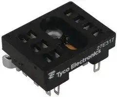
27E317
RELAY SOCKET
⚠️ Reference pricing provided. In case of supply shortages, we will connect you with our trusted procurement partners to ensure your project's continuity.
- Manufacturer: TE CONNECTIVITY - POTTER&BRUMFIELD
- Product type: Relay Sockets
- Socket Mounting:Bracket; Socket Terminals:Solder Lug; No. of Pins:10Pins; Current Rating:10A; Voltage Rating:-; Product Range:-; Accessory Type:Relay Socket; Contact Termination:Solder; No. of Contacts:60Co
- SVHC: No SVHC (25-Jun-2025)
- No. of Pins: 10Pins
| Delivery and price | |
|---|---|
| Units per pack | 540 |
| Price | 2.67 € |
| Current stock | 10+ |
| Lead time | 30 days |
Datasheet

Signal Signal Relays

**Potter & Brumfield**

## **Sockets & Accessories, R10 Relays**

> n **Sockets for 2 - 6 pole relays**

> n **Solder, PCB or screw terminal sockets**

> n **Choice of grounding provision on sockets**

> n **Hold down springs**

> n **Plates and brackets permit various mounting options**

## **Ordering Code**

|~~**Approvals**~~||
|---|---|
|UL E59244, CSA LR15734||
|Technical data of approved types on request<br>~~**Technical Data**~~||
|Socket contact material<br>Socket body material<br>2 and 4 pole models<br>6 and 8 pole models<br>Maximum current<br>Voltage drop<br>Dielectric strength<br>Insulation resistance|Spring brass, tin plated<br>Polyester<br>Phenolic<br>10A<br>30mV  max. at 10A<br>1,000Vrms<br>109megΩ|


## Solder and PC terminal sockets

Rugged, molded socket body retains floating terminals of either solder or printed circuit pin configuration.  PC terminal sockets are offered with pins in either 0.1” (2.54mm) grid or in-line arrangement.

## Grounding provisions

|27E125<br>27E126<br>27E127<br>27E162<br>27E163<br>27E164<br>27E128<br>27E129<br>27E130<br>27E212<br>27E213<br>27E271<br>27E193<br>27E194<br>27E636<br>27E637<br>27E342<br>27E629<br>27E630|2<br>4<br>6<br>2<br>4<br>6<br>2<br>4<br>6<br>2<br>4<br>6<br>2<br>4<br>2<br>4<br>2<br>4<br>6|solder terminals|strip|1393143-8<br>1393143-9<br>1-1393143-0<br>1-1393143-6<br>1-1393143-7<br>1-1393143-8<br>1-1393143-1<br>1-1393143-2<br>1-1393143-3<br>2-1393143-4<br>2-1393143-5<br>3-1393143-1<br>2-1393143-1<br>2-1393143-2<br>5-1393143-0<br>5-1393143-1<br>3-1393143-6<br>4-1393143-8<br>4-1393143-9|
|---|---|---|---|---|
||||none||
|||PCB terminals,.180”<br>(4.57mm) long,<br>staggered layout|strip||
||||none||
||||terminal||
|||PCB terminals, 210”<br>(5.33mm) long,<br>staggered layout|strip||
|||PCB terminals,.180”<br>(4.57mm) long,<br>in-line layout|none||


All accessories must be ordered separately.

Pre-installed on sockets Not for use at 5A AC and above.

Grounding Strip: Mounting stud of relay contacts grounding strip.  Grounding strip is grounded with screw or rivet through round hole in socket. Grounding Terminal (PC sockets only): Mounting stud of relay contacts ground terminal through square hole in socket.

**Strip**

**Terminal**

## **Caution:**

Printed circuit sockets are manufactured with “floating” (loose) terminals.  This permits them to align with holes in the circuit board and with the relay terminals.  During the mounting and soldering of the socket, vertical float should be eliminated and the terminals seated on the board.  (This may be accomplished by inserting a dummy relay in the socket.)  Failure to eliminate float may cause fracture of the solder joint or separation of the copper conductor from the printed circuit board when a relay is inserted in the socket after soldering.

161

10-2012, Rev. 1012 Catalog and product specification according www.te.com to IEC 61810-1 and to be used only together © 2012 Tyco Electronics Corporation, with the ‘Definitions’ section. a TE Connectivity Ltd. company.

Catalog product data, ‘Definitions’ section, application notes and all specifications are subject to change.

Catalog and product data is subject to the terms of the disclaimer and all chapters of the ‘Definitions’ section, available at http://relays.te.com/definitions

Signal Signal Relays

**Potter & Brumfield**

## **Sockets & Accessories, R10 Relays** (Continued)

## **Dimensions**

Solder and PC terminal sockets

## **PCB layout**

Sockets with staggered PC terminals

**==> picture [235 x 201] intentionally omitted <==**

**----- Start of picture text -----**<br>
2 POLE   .978 (24.84) .175<br>4 POLE 1.184 (30.07) (4.45) .750<br>6 POLE 1.390 (35.31) (19.05)<br>.210<br>.350 A (5.33)<br>(8.89)<br>.032 .065<br>.330<br>(.81) (1.65)<br>(8.38) B<br>1A .235 OTT .090 Th<br>(5.97) (2.29) .045 x .090<br>.625<br>(1.14 x 2.28)<br>(15.88)<br>CLEARANCE<br>bpOg Og 0g | |= HOLE FOR RELAY MNTG.STUD &  —  PC Socket  Term. Length  .180 in  Dim.  .180  A  Dim. .115 B<br>2 POLE (7.92).312 GROUNDSPRING .210 in  (4.57) (2.92).210  .156<br>.519 .120 DIA. (5.33) (3.96)<br>4 POLE<br>(13.18) HOLE<br>6 POLE (18.42).725 (4.19).165 (3.05) TOLERANCES (          )±  .25±.010<br>UNLESS OTHERWISE SH OWN<br>**----- End of picture text -----**<br>


**==> picture [214 x 134] intentionally omitted <==**

**----- Start of picture text -----**<br>
.500<br>(12.70)<br>.100<br>(2.54) 6<br>GRID 4 POLE<br>POLE<br>.500 2<br>(12.70) oi POLE<br>HOLES<br>.100<br>+ .004 .150<br>.056 DIA. (2.54)<br>- .000 (3.81)<br>.450<br>+   .10 HOLE FOR GROUND<br>1.42 (11.43)<br>(          )-   .00 TERMINAL (IF REQ’D.)<br>**----- End of picture text -----**<br>


Sockets with inline PC terminals

## **PCB layout (top view)**

Sockets with solder terminals

**==> picture [178 x 128] intentionally omitted <==**

**----- Start of picture text -----**<br>
.281 2 POLE .343 (8.71)<br>(7.14) 4 POLE .562 (14.27)<br>6 POLE .781 (19.84)<br>aa4<br>+ + 2 HOLES<br>9 OF .109 DIA.<br>.140 (2.77)<br>(3.56) tt .354 .281 ± .015<br>(8.99)<br>.656 ± .015 port (7.14 ± .38)<br>(16.66 ± .38)<br>**----- End of picture text -----**<br>


**==> picture [128 x 122] intentionally omitted <==**

**----- Start of picture text -----**<br>
.210<br>(5.33) .530<br>.320 .420 (13.46)<br>(8.13) (10.67)<br>.400 .550<br>.110<br>a H (10.16) (13.97)<br>(2.79) 0-0-0.— HOLES<br>+ .004<br>.450 .056 DIA.<br>- .000<br>(11.43)<br>+   .10<br>1.42<br>(         )-   .00<br>—_<br>**----- End of picture text -----**<br>


162

Catalog and product specification according to IEC 61810-1 and to be used only together with the ‘Definitions’ section.

Catalog product data, ‘Definitions’ section, application notes and all specifications are subject to change.

Catalog and product data is subject to the terms of the disclaimer and all chapters of the ‘Definitions’ section, available at http://relays.te.com/definitions

10-2012, Rev. 1012 www.te.com © 2012 Tyco Electronics Corporation, a TE Connectivity Ltd. company.

Signal Signal Relays

**Potter & Brumfield**

## **Sockets & Accessories, R10 Relays** (Continued)

## **Ordering Code**

|**Product**<br>**Code**|**Product**<br>**Poles **|**Terminal**<br>**type**|**Terminal**<br>**Mount**<br>**type**|**Grounding**<br>**provision**|**Part**<br>**number**|
|---|---|---|---|---|---|
|27E317<br>27E152|2<br>4|solder|bracket|strip|3-1393143-4<br>1-1393143-5|
|27E446<br>27E447<br>27E448|2<br>4<br>6|solder|flange|strip|4-1393143-1<br>4-1393143-2<br>4-1393143-3|
|27E460<br>27E461<br>27E462|2<br>4<br>6|screw|track/<br>chassis|none|1393837-1<br>4-1393143-4<br>4-1393143-5|


All accessories must be ordered separately.

## **Dimensions**

## Bracket Mount socket 27E317 and 27E152

Allows solder terminal relay to mount flat on a chassis.

Track mount sockets 27E460, 27E461, 27E462 Provides front wiring, screw terminal connections for R10 family relays. No grounding provision.

## 2 pole terminal wiring code

**==> picture [177 x 117] intentionally omitted <==**

**----- Start of picture text -----**<br>
X=              (24.84)2 POLE .978 .85 MAX.(21.6) P a nang<br>4 POLE 1.184<br>             (30.07) a \O) mmo<br>X<br>.075<br>.210 TYP. (1.91) .437<br>(5.33) (11.10)<br>.150<br>— .484 4 (3.81)<br>—a (12.29) L v + l )4<br>.045 x .090 TYP. .156 .058<br>(1.14 x 2.28) (3.96) .437 (1.47)MATERIAL<br>TAPPED #6-32 THREAD Fe i (11.10) - THICKNESS<br>**----- End of picture text -----**<br>


## Flange mount socket 27E446, 27E447, 27E448

Solder terminal socket with tin-plated terminals and grounding strip pre-assembled on .065” (1.65mm) steel mounting plate.  Requires only one chassis cutout.

**==> picture [193 x 171] intentionally omitted <==**

**----- Start of picture text -----**<br>
(2) MTNG. HOLES<br>.187 DIA.<br>(4.75) #6-32 SCREWS .100<br>Isl 6 om + 10 ISI aofel (2.54)<br>is 7 ++++++ 8 SI<br>5 +++ 9<br>is 1 [| +++ 4 SI A B |<br>2 3<br>fo : .062 ± .007<br>+ (1.57 ± .178)<br>?<br>C<br>2.75 ± .015 1.375 ± .010 .530 MAX.<br>(69.85 ± .381) (34.93 ± .254) (13.46)<br> Socket  Poles  Dim A  Dim B  Dim C<br> 27E446  2  1.437  1.822  .937<br>(36.50)  (46.27)  (23.80)<br> 27E447  4  1.687  2.072  1.125<br>(42.85)  (52.63)  (28.58)<br> 27E448  6  1.875  2.260  1.343<br>(47.63)  (57.40)  (34.11)<br>**----- End of picture text -----**<br>


**==> picture [217 x 113] intentionally omitted <==**

**----- Start of picture text -----**<br>
.780 MAX. .175 REF. .045 x .090<br>(19.81) (4.45) (1.14 x 2.28)<br>SLOT IN TERMINAL S<br>k .065 2 HOLES<br>ae (1.65) .687 .147 DIA.(3.73)<br>ade | . on (17.45)<br>a f<br>A B C<br>GD<br>nooo .210<br>(5.33)<br>| e- | — 7 Oo7<br>2 MTG. HOLES =e .320 REF. .25<br>.147 DIA. .187 ± .010 (8.13) (6.35)<br>(3.73) (4.75 ± .25)<br>SUGG<br>CHASSIS  CUTOUT<br>**----- End of picture text -----**<br>


**==> picture [248 x 208] intentionally omitted <==**

**----- Start of picture text -----**<br>
4 pole terminal wiring code 6 pole terminal wiring code<br>9 + 15 193 + 1221<br>MIS 10 o ++ +++ + 16 WwWIS ~~+. 11 o 22 il<br>ISIISS 875 | + + +++ +++ + | 131411 ISIISS ISS[SIist 1087 ++ +++ +++ +++ +++ + 219170 SISIis]<br>SINe 61 c 124 ISW ic~ 56 + + + 1614 Is~<br>Ist 2 °° + 3 Wl it 115 s: + 148 iat<br>2 3<br>SSI ISI ist *o is<br>Suggested track mounting Suggested chassis mounting<br>27EXXX<br>.187 MIN .(4.75) PC BOARD27EXXX .187 MIN .(4.75) PC BOARD /<br>Y Y<br>1.12L x .41W x .26HINSULATOR40G432 = (34.93)1.375 24A07124A110TRACK rT CHASSISSUGGESTED STANDOFF \<br>(28.4 x 10.4 x 6.60) MOUNTING CLIP<br>.375 (9.53) DIA. MIN;<br>.625 (15.88) DIA. MAX.<br>(CUSTOMER SUPPLIED)<br>**----- End of picture text -----**<br>


OR INSULATOR (40G432)

163

10-2012, Rev. 1012 Catalog and product specification according www.te.com to IEC 61810-1 and to be used only together © 2012 Tyco Electronics Corporation, with the ‘Definitions’ section. a TE Connectivity Ltd. company.

Catalog product data, ‘Definitions’ section, application notes and all specifications are subject to change.

Catalog and product data is subject to the terms of the disclaimer and all chapters of the ‘Definitions’ section, available at http://relays.te.com/definitions

Signal Signal Relays

**Potter & Brumfield**

## **Sockets & Accessories, R10 Relays** (Continued)

## **Ordering Code**

|**Product**<br>**Code**|**Product**<br>**Description**|**Part**<br>**number**|
|---|---|---|
|20C249<br>20C250<br>20C251<br>20C266|Hold down spring for 2 pole R10 relays<br>Hold down spring for 4 pole R10 relays<br>Hold down spring for 6 pole R10 relays<br>Hold downspringfor8 poleR10relays|3-1393159-5<br>3-1393159-6<br>3-1393159-7<br>4-1393159-1|
|20C259|Hold downstrapfor R10relaysin PC sockets|4-1393159-0|
|20C300<br>20C301|Hold down spring for 2 pole R10S relays<br>Hold downspringfor 4poleR10Srelays|4-1393159-4<br>4-1393159-5|
|37D645|Mounting strip-accepts10relays orsockets|7-1393143-3|
|24A110|Mountingtrack|1419111-6|
|24A071|Steel mounting clip with #6-32 screw -<br>usewith 27E46_ sockets on 24A110track|1419111-5|
|40G432|Plastic insulator - use with use with 27E46_|9-1393159-5|
||sockets on chassis or with 24A071 clip on||
||24A110track||


**==> picture [156 x 17] intentionally omitted <==**

**----- Start of picture text -----**<br>
Hold down spring  Hold down strap<br>(PC sockets only)<br>**----- End of picture text -----**<br>


All accessories must be ordered separately.

## **Dimensions**

## 37D645 – Mounting Strip

Strip of .060” (1.52mm) aluminum contains ten pre-punched, breakaway mounting plates. Each plate accomodates a 2, 4, 6 or 8 pole solder terminal R10 relay or socket to facilitate chassis- or rack mounting.

**==> picture [150 x 126] intentionally omitted <==**

**----- Start of picture text -----**<br>
.535 1.205<br>(13.59) 1.205 (30.61) .090 R.<br>.25 .13 (30.61) (2.29)<br>(6.4) (3.3)<br>“A” = .109 DIA.<br>2.000 (2.77)<br>(50.80)<br>2.50 .090<br>(63.5) “A”  + + “A”  + + (2.29)<br>.180<br>(4.57)<br>1.135<br>T ene (28.83) .16<br>.32 (4.1)<br>(8.1)<br>**----- End of picture text -----**<br>


## 24A110 – Mounting track

Mounting track is designed to accept snap-mount sockets, as well as other P&B screw terminal sockets.  Track is made of lightweight, sturdy extruded aluminum and is shipped in three-foot (914cm) lengths with mounting holes on six-inch (152mm) centers.  Track can be cut to shorter lengths or used end-to-end.

**==> picture [222 x 71] intentionally omitted <==**

**----- Start of picture text -----**<br>
36.00 ± .060<br>3.00 6.00 (914.4 ± 1.52) 1.375 ± .010<br>(76.2) (152.4) (34.93 ± .254)<br>.750 .187 .405 ± .007<br>(19.05) (4.75) (10.29 ± .178)<br>**----- End of picture text -----**<br>


**==> picture [213 x 61] intentionally omitted <==**

**----- Start of picture text -----**<br>
24A110<br>40G432<br>@ 24A071<br>**----- End of picture text -----**<br>


164

Catalog and product specification according to IEC 61810-1 and to be used only together with the ‘Definitions’ section.

Catalog product data, ‘Definitions’ section, application notes and all specifications are subject to change.

Catalog and product data is subject to the terms of the disclaimer and all chapters of the ‘Definitions’ section, available at http://relays.te.com/definitions

10-2012, Rev. 1012 www.te.com © 2012 Tyco Electronics Corporation, a TE Connectivity Ltd. company.
Updated at June 6, 2026
About Novapart
Novapart is a B2B electronic component broker specialising in stock shortages and cost reduction. We source hard-to-find parts and identify compliant alternatives across a catalogue of 410,000+ components from 500+ manufacturers.
Learn more →Stock Shortage Specialist
When a component is unavailable, discontinued or has an unacceptable lead time, we tap into our network of vetted European and Asian distributors to source what you need — without compromising on quality or traceability.
Request a quote →Compliant Alternatives
We identify pin-to-pin, electrically equivalent substitutes that meet the same certifications (RoHS, AEC-Q100, REACH) as your original specification — validated against datasheets, not just part numbers. Often at a lower cost.
BOM Analysis service →