
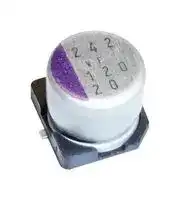


25SVF56M
Polymer Aluminium Electrolytic Capacitor, 56 µF, 25 V, Radial Can - SMD, 0.03 ohm
- Manufacturer: PANASONIC
- Product type: Aluminium Polymer Capacitors
- Capacitance:56µF; Voltage Rating:25V; AE Capacitor Case:Radial Can - SMD; Product Range:OS-CON SVF Series; ESR:0.03ohm; Lifetime @ Temperature:1000 hours @ 125°C; Operating Temperature Min:-55°C; Operatin
- ESR: 0.03ohm
- SVHC: No SVHC (25-Jun-2025)
- Capacitance: 56µF
- Voltage(DC): 25V
- Product Range: OS-CON SVF Series
- Product Width: -
- Product Height: 5.9mm
- Product Length: -
- Ripple Current: 880mA
- Product Diameter: 6.3mm
- Capacitor Mounting: Surface Mount
- Capacitor Terminals: Solder
- Capacitance Tolerance: ± 20%
- Lifetime @ Temperature: 1000 hours @ 125°C
- Capacitor Case / Package: Radial Can - SMD
- Operating Temperature Max: 125°C
- Operating Temperature Min: -55°C
| Delivery and price | |
|---|---|
| Units per pack | 20 |
| Price | 0.664 € |
| Current stock | 1000+ |
| Lead time | 30 days |
## **Conductive Polymer Aluminum**

## **Solid Capacitors**

## Surface Mount Type

**SVF** series

## Ce

## **Features**

- High voltage (50 V max.)

- Large capacitance (1000 μF max.)

- 125 ℃ 1000 h

- RoHS compliance, Halogen free

## Ce **Specifications**

|Size code|B6<br>~~a~~|C6|C6|E7|E12|F10|F12|
|---|---|---|---|---|---|---|---|
|Category temp. range|–55℃to +125℃<br>~~a~~|||||||
|Rated voltage range|16 V to 25 V<br>~~a~~<br>~~ee~~|16 V to 50 V||||16 V|16 V to 50 V|
|Nominal cap.range|27 μF to 82 μF<br>~~a~~<br>~~ee~~|10 μF to 180 μF||18 μF to 270 μF|39 μF to 560 μF|1000 μF|68 μF to 1000 μF|
|Capacitance tolerance|±20 %(120 Hz / +20℃)<br>~~ee~~|||||||
|DC leakage current|Please see the attached characteristics list|||||||
|Dissipation factor (tan δ)|Please see the attached characteristics list|||||||
|Endurance|+125℃1000 h, rated voltage applied|||||||
||Capacitance change<br>Within ±20 % of the initial value<br>~~PO~~||Within ±20 % of the initial value|||||
||Dissipation factor (tanδ)<br> <br>~~PO~~<br>~~PO~~||≦200 % of the initial limit|||||
||DC leakage current<br>Within the initial limit<br>~~PO~~<br>~~Pe~~||Within the initial limit|||||
|Damp heat<br>(Steady state)|+60℃, 90 % to 95 % RH, 1000 h, No-applied voltage<br>~~Pe~~|||||||
||Capacitance change<br>Within ±20 % of the initial value<br>~~PO~~||Within ±20 % of the initial value|||||
||Dissipation factor (tanδ)<br> <br>~~PO~~<br>~~PO~~<br>~~|~~<br>~~ti“~~<br>~~:s~sCSCsz~~||≦150 % of the initial limit|||||
||DC leakage current<br>Within the initial limit (after voltage processing)<br>~~PO~~<br>~~|~~<br>~~ti“~~<br>~~:s~sCSCsz~~||Within the initial limit (after voltage processing)|||||


|**Marking**<br>**Dimensions (not to scale)**<br>~~esee~~|**Marking**<br>**Dimensions (not to scale)**<br>~~esee~~|**Marking**<br>**Dimensions (not to scale)**<br>~~esee~~|**Marking**<br>**Dimensions (not to scale)**<br>~~esee~~|**Marking**<br>**Dimensions (not to scale)**<br>~~esee~~|**Marking**<br>**Dimensions (not to scale)**<br>~~esee~~|**Marking**<br>**Dimensions (not to scale)**<br>~~esee~~|**Marking**<br>**Dimensions (not to scale)**<br>~~esee~~|**Marking**<br>**Dimensions (not to scale)**<br>~~esee~~|**Marking**<br>**Dimensions (not to scale)**<br>~~esee~~|**Marking**<br>**Dimensions (not to scale)**<br>~~esee~~|**Marking**<br>**Dimensions (not to scale)**<br>~~esee~~|**Marking**<br>**Dimensions (not to scale)**<br>~~esee~~|**Marking**<br>**Dimensions (not to scale)**<br>~~esee~~|**Marking**<br>**Dimensions (not to scale)**<br>~~esee~~|**Marking**<br>**Dimensions (not to scale)**<br>~~esee~~|**Marking**<br>**Dimensions (not to scale)**<br>~~esee~~|**Marking**<br>**Dimensions (not to scale)**<br>~~esee~~|**Marking**<br>**Dimensions (not to scale)**<br>~~esee~~|**Marking**<br>**Dimensions (not to scale)**<br>~~esee~~|**Marking**<br>**Dimensions (not to scale)**<br>~~esee~~|**Marking**<br>**Dimensions (not to scale)**<br>~~esee~~|**Marking**<br>**Dimensions (not to scale)**<br>~~esee~~|**Marking**<br>**Dimensions (not to scale)**<br>~~esee~~|**Marking**<br>**Dimensions (not to scale)**<br>~~esee~~|
|---|---|---|---|---|---|---|---|---|---|---|---|---|---|---|---|---|---|---|---|---|---|---|---|---|
|||||||||||||||0.2 max.|||||||||||
||Polarity marking (−)|||Polarity marking (−)|||Series code*<br>Lot No.||||L<br>øD<br>~~—~~<br>~~er~~<br>~~L~~o <br>~~SS~~|||||R<br>C<br>P<br>H<br>W<br>⊖<br>⊕<br>~~a~~<br> ~~Le~~<br>~~ee~~|||||||||
||||||||||||||||||||||||||
|||||||||||||||||||||||||Unit:mm|
||R. voltage||||||R. capacitance<br>(μF)||||Size<br>code|øD±0.5||L<br>W±0.2<br>+0.1<br>-0.4||H±0.2||C±0.2||||R||P*2|
||(V)||||||||||B6|5.0||5.9<br>5.3||5.3|||6.0|||0.6 to 0.8||1.4|
||||||||||||C6|6.3||5.9<br>6.6||6.6|||7.3|||0.6 to 0.8||2.1|
||||||||||||E7|8.0||6.9<br>8.3||8.3|||9.0|||0.6 to 0.8||3.2|
||||||||||||E12|8.0||11.9<br>8.3||8.3|||9.0|||0.8 to 1.1||3.2|
||||||||||||F10|10.0||10.0*1<br>10.3||10.3||11.0||||0.8 to 1.1||4.6|
||* Depends on the case size.||||* Depends on the case size.||||||F12|10.0||10.3<br>12.6||10.3||11.0||||0.8 to 1.1||4.6|
|||||||||||||||||||||||*1 : ±0.5, *2 : Reference|||


Design and specifications are each subject to change without notice. Ask factory for the current technical specifications before purchase and/or use. Should a safety concern arise regarding this product, please be sure to contact us immediately.

28-Jun-19

**SVF series**

## **Characteristics list**

|Rated<br>voltage<br>(V)|Rated<br>capacitance<br>(±20 %)<br>(μF)|Case size<br>(mm)|Case size<br>(mm)|Size<br>code|Specifications|Specifications|Specifications|Specifications|Specifications|Standard (Reel size : ø380)|Standard (Reel size : ø380)|
|---|---|---|---|---|---|---|---|---|---|---|---|
|||øD|L||Ripple<br>current*1<br>(mA rms)|Allowable<br>ripple<br>current*1<br>(mA rms)|ESR*2<br>(mΩ max.)|tan δ*3|LC*4<br>(μA)|Part number|Min.<br>Packaging<br>Q'ty<br>(pcs)|
|16|82|5.0|5.9|B6|940|3000|27|0.12|262|16SVF82M|1500|
||180|6.3|5.9|C6|1040|3300|22|0.12|576|16SVF180M|1000|
||270|8.0|6.9|E7|1040|3300|22|0.12|864|16SVF270M|1000|
||560|8.0|11.9|E12|1560|4950|14|0.12|1792|16SVF560M|400|
||1000|10.0|10.0|F10|1350|4300|16|0.12|3200|16SVF1000MX|500|
|||10.0|12.6|F12|1700|5400|12|0.12|3200|16SVF1000M|400|
|20|56|5.0|5.9|B6|880|2800|30|0.12|224|20SVF56M|1500|
||120|6.3|5.9|C6|1010|3200|25|0.12|480|20SVF120M|1000|
||180|8.0|6.9|E7|1010|3200|25|0.12|720|20SVF180M|1000|
||390|8.0|11.9|E12|1560|4950|14|0.12|1560|20SVF390M|400|
||560|10.0|12.6|F12|1700|5400|12|0.12|2240|20SVF560M|400|
|25|27|5.0|5.9|B6|770|2450|40|0.12|135|25SVF27M|1500|
||47|6.3|5.9|C6|880|2800|30|0.12|235|25SVF47M|1000|
||56|6.3|5.9||880|2800|30|0.12|280|25SVF56M|1000|
||82|8.0|6.9|E7|940|3000|28|0.12|410|25SVF82M|1000|
||100|8.0|6.9||1010|3200|24|0.12|500|25SVF100M|1000|
||180|8.0|11.9|E12|1470|4650|16|0.12|900|25SVF180M|400|
||330|10.0|12.6|F12|1580|5000|14|0.12|1650|25SVF330M|400|
|35|22|6.3|5.9|C6|820|2600|35|0.12|154|35SVF22M|1000|
||39|8.0|6.9|E7|880|2800|30|0.12|273|35SVF39M|1000|
||82|8.0|11.9|E12|1260|4000|20|0.12|574|35SVF82M|400|
||120|10.0|12.6|F12|1390|4400|18|0.12|840|35SVF120M|400|
|50|10|6.3|5.9|C6|790|2500|40|0.12|100|50SVF10M|1000|
||18|8.0|6.9|E7|850|2700|35|0.12|180|50SVF18M|1000|
||39|8.0|11.9|E12|1200|3800|25|0.12|390|50SVF39M|400|
||68|10.0|12.6|F12|1350|4300|20|0.12|680|50SVF68M|400|


- *1: Ripple current (100 kHz / +105 ℃ < Tx ≦ +125 ℃) /Allowable ripple current (100 kHz / Tx ≦ +105 ℃)

- *2: ESR (100 kHz to 300 kHz / +20 ℃)

- *3: tan δ (120 Hz / +20 ℃)

- *4: After 2 minutes

- Please refer to each page in this catarog for “Reflow conditions” and “Taping specifications”.

## **Frequency correction factor for ripple current**

|Frequency(f)|120 Hz≦f < 1 kHz|1 kHz≦f < 10 kHz|10 kHz≦f < 100 kHz|100 kHz≦f < 500 kHz|
|---|---|---|---|---|
|Coefficient|0.05|0.3|0.7|1|


Design and specifications are each subject to change without notice. Ask factory for the current technical specifications before purchase and/or use.

Should a safety concern arise regarding this product, please be sure to contact us immediately.

28-Jun-19

## **Guidelines and precautions regarding the technical information and use of our products described in this online catalog.**

- If you want to use our products described in this online catalog for applications requiring special qualities or reliability, or for applications where the failure or malfunction of the products may directly jeopardize human life or potentially cause personal injury  (e.g. aircraft and aerospace equipment, traffic and transportation equipment, combustion equipment, medical equipment, accident prevention, anti-crime equipment, and/or safety equipment), it is necessary to verify whether the specifications of our products fit to such applications. Please ensure that you will ask and check with our inquiry desk as to whether the specifications of our products fit to such applications use before you use our products.

- The quality and performance of our products as described in this online catalog only apply to our products  when used in isolation. Therefore, please ensure you evaluate and verify our products under the specific circumstances in which our products are assembled in your own products and in which our products will actually be used.

- Please ensure the safety by means of protection circuit, redundant circuit etc. in your system design in order to prevent the occurrence of life crisis and other serious damages due to the failure of our products.

- The products and product specifications described in this online catalog are subject to change for improvement without prior notice. Therefore, please be sure to request and confirm the latest product specifications which explain the specifications of our products in detail, before you finalize the design of your applications, purchase, or use our products.

- The technical information in this online catalog provides examples of our products' typical operations and application circuits. We do not guarantee the non-infringement of  third party's intellectual property rights and we do not grant any license, right, or interest in our intellectual property.

- If any of our products, product specifications and/or technical information in this catalog is to be exported, the laws and regulations of the exporting country, especially with regard to security and export control, shall be observed.

## **<Regarding the Certificate of Compliance with**

## **the EU RoHS Directive/REACH Regulations>**

- The switchover date for compliance with the RoHS Directive/REACH Regulations varies depending on the part number or series of our products.

- When you use the inventory of our products for which it is unclear whether those products are compliant with the RoHS Directive/REACH Regulation, please select "Sales Inquiry" in the website inquiry form and contact us.

**Please note that we do not owe any liability and responsibility if our products are used beyond the description of this catalog or without complying with precautions in this catalog.**

10-Feb-23

**Notices / Items to be observed**

## **Notices**

## **■ Applicable laws and regulations**

・ This product complies with the RoHS Directive (Restriction of the use of certain hazardous substances in electrical and electronic equipment (DIRECTIVE 2011/65/EU and(EU)2015/863)).

- ・ No Ozone Depleting Chemicals(ODC's), controlled under the Montreal Protocol Agreement, are used in producing

   - this product. We do not use PBBs or PBDEs as brominated flame retardants.

- ・ Follow export procedures in accordance with the Foreign Exchange and Foreign Trade Law and other export-related laws and regulations when exporting this product.

- ・ These products are not dangerous goods on the transportation as identified by UN(United Nations) numbers or UN classification.

## **■ Limited applications**

・ This capacitor is designed to be used for electronics circuits such as audio/visual equipment, home appliances, computers and other office equipment, optical equipment, measuring equipment.

・ An advanced specification must be signed individually for high-reliability use that might threaten human life or property due to a malfunction of the capacitor.

## **■ Intellectual property rights and licenses**

・ The technical information in this specification provides examples of our products' typical operations and application circuits. We do not guarantee the non-infringement of third party's  intellectual property rights and we do not grant any license, right, or interest in our intellectual property.

## **Items to be observed**

## **■ For specification**

- ・ This specification guarantees the quality and performance of the product as individual components. The durability differs depending on the environment and the conditions of usage.

   - Before use, check and evaluate their compatibility with actual conditions when installed in the products. When safety requirements cannot be satisfied in your technical examination, inform us immediately.

- ・ Do not use the products beyond the specifications described in this document.

## **■ Upon application to products where safety is regarded as important**

If a malfunction of this product may result in the loss of human life or other serious damage, in traffic transportation equipment (trains, automobiles, traffic signals, etc.), medical equipment, aerospace equipment, electric heating equipment, combustion and gas equipment, rotating equipment, disaster prevention and security equipment, etc., ensure safety by giving sufficient consideration to a fail-safe design, for example, by considering the following items.

- (1) The system is equipped with a protection circuit and protection device.

- (2) The system is equipped with a redundant circuit or other system to prevent an unsafe status in the event of a single fault.

## **■ Conditions of use**

- ・ Before using the products, carefully check the effects on their quality and performance, and determined whether or not they can be used. These products are designed and manufactured for general-purpose and standard use in general electronic equipment. These products are not intended for use in the following special conditions.

   - (1)  In liquid, such as Water, Oil, Chemicals, or Organic solvent.

   - (2)  In direct sunlight, outdoors, or in dust.

   - (3)  In vapor, such as dew condensation water of resistive element, or water leakage, salty air, or air with a high concentration corrosive gas, such as Cl2, H2S, NH3, SO2, or NOx.

   - (4)  In an environment where strong static electricity or electromagnetic waves exist.

   - (5)  Mounting or placing heat-generating components or inflammables, such as vinyl-coated wires, near  these products.

   - (6)  Sealing or coating of these products or a printed circuit board on which these products are mounted, with resin and other material.

   - (7)  Using resolvent, water or water-soluble cleaner for flux cleaning agent after soldering. (In particular, when using water or a water-soluble cleaning agent, be careful not to leave water residues)

   - (8)  Using in the atmosphere where strays acid or alkaline.

   - (9)  Using in the atmosphere where there are excessive vibration and shock.

   - (10) Using in the atmosphere where there are low pressure or decompression.

- ・ Please arrange circuit design for preventing impulse or transitional voltage.

Ensure that the voltage is lower than the rated voltage in the following condition: shock voltage circuits, transient phenomena in which excessive high voltage is applied in a short period of time, or when pulse high voltage is applied.

- ・ Our products there is a product are using an electrolyte solution. Therefore, misuse can result in rapid deterioration of characteristics and functions of each product. Electrolyte leakage damages printed circuit and affects performance, characteristics, and functions of customer system.

10-Feb-23

**Conductive Polymer Aluminum Solid Capacitors**

## **- Application Guidelines (OS CON)**

## **1. Circuit design**

## **1.1 Prohibited circuits**

- (1) Leakage current of the OS-CON may increase in the following conditions.

   - (a) Soldering

   - (b) When voltage is not applied : high temperature no-load test, high temperature and high humiditynoload test, rapidly changing temperature test, etc.

- (2) Avoid the use of the OS-CON in the following type of circuits because leakage current may increase.

   - (a) High-impedance circuits

   - (b) Coupling circuits

   - (c) Time constant circuits

   - (d) Other circuits that are significantly affected by leakage current.

      - ✽ If you plan to use 2 or more OS-CONs in a series connection, please contact us before use。

## **1.2 Failure and life-span**

The failure rate is 0.5 % /1000 h (Confidence level : 60 %) based on JIS C 5003.

The prospective failure is not zero. The mainly failure modes are as follows.

## **1.2-1 Contingency failure**

The most common failure mode is a short circuit. Mainly caused by the soldering or operating temperature environment, along with heat stresses, electrical stresses or mechanical stressesas follows.

   - ・ Applying voltage over the rated voltage.

   - ・ Applying reverse voltage

   - ・ Excessive mechanical stress

   - ・ Applying rush current by sudden charge or discharge out of the specification.

- (1) The following phenomenon is seen when short-current is applied to the OS-CON.

   - (a) When current is relatively low. (ø10 : approx 1 A or less, ø8 : approx 0.5 A or less, ø6.3 : approx 0.2 A or less) The OS-CON becomes heated, but no effects are visible even when the current is continously carried.

   - (b) When the short circuit currents exceed the mentioned value above.

After internal temperature increase, sealing rubber may be turned over.

      - In some cases, odorous gas may be produced.

- (2) In case a short circuit occurs, ensure safety by fully considering the followings.

   - (a) If odorous gas is released, turn off the main power of the equipment.

      - In this case, keep your face and hands away from the area.

   - (b) It may take a few seconds to a few minutes for odor gas to be generated depending on the conditions. When using a protective circuit, design the product so that it operates during this period.

   - (c) If the gas comes into eyes, rinse immediately. If the gas is inhaled, gargle immediately.

   - (d) Do not lick the electrolyte. If the electrolyte touches skin, wash it off with soap immediately.

   - (e) OS-CON contains combustibles. The short-circuit part may spark and catch fire if the current value after a short-circuit is extremely large. Provide for safety designs such as redundant design and protection circuit.

## **1.2-2 Wear-out failure (life time)**

When lifetime span exceeded the specified guarantee time of endurance and damp heat, electrolyte might insulate and cause electric characteristic changed. This is called an open circuit.

The electric characteristics of capacitance and ESR may possibly change within the specified range in specifications even if it is used under the condition of the rated voltage, electric and mechanical performance. Please note it when designing.

## **1.3 Leakage current**

Mechanical stress may cause OS-CON’s leakage current increased.

In such a case, leakage current will gradually decrease by applying voltage (withinthe category voltage and the upper limit of category temperature).

## **1.4 Rapid charge and discharge limitation**

Allowance of a large rush current to flow due to rapid charge and discharge may result in short circuit or large leakage current. The protection circuit, to maintain high reliability, is recommended when rush current to flow to the OS-CON is in the following cases.

- (1) Products which 10 times of allowable ripple current is less than 10 A : It is when 10 A or over of rush current is applied.

- (2) Products which 10 times of allowable ripple current is 10 A or over : It is when rush current, which the figure is over 10 times of allowable ripple current, is applied.

05-Mar-21

**Conductive Polymer Aluminum Solid Capacitors**

## **2. Mounting**

## **2.1 Soldering with a soldering iron**

- (1) When lead terminals for radial lead type must be processed because the lead pitch and the PCB holes do not match, process them without any stresses to the OS-CON before soldering.

- (2) Solder without any excessive stresses to the OS-CON itself.

- (3) When the OS-CON has been soldered once and needs to be removed, remove it after the solder has been completely melted.

- (4) Do not let the tip of the soldering iron touch the OS-CON itself.

## **2.2 Flow soldering**

- (1) Do not apply flow soldering to OS-CON SMD type.

- (2) Do not solder the OS-CON itself by submerging it in melted solder.

- (3) Solder the opposite side that the OS-CON is mounted on.

- (4) Note that flux does not adhere to anywhere expect the lead terminal.

- (5) Note that other components do not fall over and touch the OS-CON when soldering.

## **2.3 Reflow soldering**

- (1) Do not apply reflow soldering to OS-CON Radial Lead type.

- (2) Please contact us for setting VPS conditions.

## **2.4 Capacitor handling after soldering**

Do not subject the OS-CON to excessive stress as follows.

- (1) Do not tilt, bend or twist the OS-CON.

- (2) Do not move the PCB with holding the OS-CON itself.

- (3) Do not hit the OS-CON with objects.

- (4) When stacking PCBs, make sure that the OS-CON does not touch other PCBs or components.

## **2.5 Circuit board cleaning**

Check the following items before washing PC board with these detergents: high quality alcohol-based cleaning fluid such as Pine-a ST-100S, clean thru 750H, 750L, 710M, 750K or Techno Care FRW 14 through 17 or detergents including substitute freon as AK-225AES or IPA.

- (1) Use immersion or ultrasonic waves to clean within 2 minutes.

- (2) The temperature of the cleaning fluid should be less than 60 °C.

- (3) Watch the contamination of the detergent such as conductivity, pH, specific gravity, water content, etc.

(4) Do not store the OS-CON in a location subject to gases from the cleaning fluid or in an airtight container after cleaning.

- (5) Dry the PCB or OS-CON with hot air that should be less than the upper category temperature.

- (6) Please note that indication may disappear when rubbing print side after washing depending on a cleaner.

- (7) Please contact us for details about detergents, cleaning methods and detergents other than those listed above.

## **2.6 Fixatives and coating materials**

(1) Select the appropriate covering and sealant materials for the OS-CON. In particular, don’t use acetone in the fixative, coating agent and diluent.

(2) Before applying the fixative or coating, completely remove any flux residue and foreign matter from the area where the board and the OS-CON will be jointed together.

(3) Allow any detergent to dry before applying the fixative or coating.

(4) Please contact us for the fixative and coating heat curing conditions.

## **2.7 Capacitor insulation**

Be sure to completely separate the case, negative lead terminal, positive lead terminal and PC board patterns with each other due to the following reasons.

(1) Insulation is not guaranteed at a part of resin on the surface of a case.

(2) It offers inconstant resistance between a case and a negative lead terminal and it isn’t insulated.

05-Mar-21

**Conductive Polymer Aluminum Solid Capacitors**

## **3. Storage**

Open the bags just before mounting and use up all products once opened, For keeping a good solderability, store the OS-CON as follows.

|||Before unsealing|After unsealing|
|---|---|---|---|
||SMD type*1|Within 24 months after shipment|Within 30 days from opening<br>(packaged with carrier tape)|
|Radial<br>lead type|Bag packing product<br>Taping product|Within 30 months after shipment<br>Within 24 months after shipment|Within 7 days from opening|


*1 : The JEDEC J-STD-020 standard is not applicable

## ✽ Intellectual property right

We, Panasonic Group are providing the product and service that customers can use without anxiety, and are working positively on the protection of our products underintellectual property rights.

Representative patents relating to OS-CON are as follows: US Patent No.7158367

05-Mar-21
Updated at April 11, 2026
Panasonic Industry is a global leader in the design and manufacture of high-quality electronic components. Renowned for a commitment to continuous innovation, the company provides the essential building blocks that empower modern engineering. From industrial automation to consumer electronics, Panasonic's components are trusted worldwide for their outstanding reliability, efficiency, and long-term performance. The extensive portfolio is anchored by a massive selection of passive components, featuring an industry-leading range of aluminium electrolytic, film, and polymer capacitors. Alongside these advanced capacitance solutions, engineers rely on Panasonic's robust power inductors and a highly versatile array of electromechanical devices, including solid-state, power, and signal relays engineered to excel in demanding environments. Beyond core passives and switching solutions, the offering encompasses critical circuit protection devices such as TVS varistors and NTC thermistors, as well as sophisticated thermal management materials. Panasonic also delivers precision light and motion sensors, highly reliable batteries, and advanced Bluetooth and WLAN connectivity modules, providing a comprehensive ecosystem of components to support next-generation technological design.
About Novapart
Novapart is a B2B electronic component broker specialising in stock shortages and cost reduction. We source hard-to-find parts and identify compliant alternatives across a catalogue of 410,000+ components from 500+ manufacturers.
Learn more →Stock Shortage Specialist
When a component is unavailable, discontinued or has an unacceptable lead time, we tap into our network of vetted European and Asian distributors to source what you need — without compromising on quality or traceability.
Request a quote →Compliant Alternatives
We identify pin-to-pin, electrically equivalent substitutes that meet the same certifications (RoHS, AEC-Q100, REACH) as your original specification — validated against datasheets, not just part numbers. Often at a lower cost.
BOM Analysis service →