


2092-1102/002-000
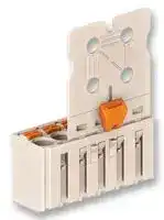
Wire-To-Board Terminal Block, 5 mm, 2 Ways, 24 AWG, 12 AWG, 1.5 mm², Push In
- Manufacturer: WAGO
- Product type: Wire-To-Board Terminal Blocks
- Pitch Spacing:5mm; No. of Positions:2Ways; Wire Size AWG Min:24AWG; Wire Size AWG Max:12AWG; Conductor Area CSA:1.5mm²; Wire Connection Method:Push In; Rated Current:16A; Rated V
- SVHC: No SVHC (21-Jan-2025)
- Pitch Spacing: 5mm
- Product Range: -
- Rated Current: 16A
- Rated Voltage: 320V
- No. of Positions: 2Ways
- Block Orientation: Through Hole Right Angle
- Wire Size AWG Max: 12AWG
- Wire Size AWG Min: 24AWG
- Conductor Area CSA: 1.5mm²
- Wire Connection Method: Push In
| Delivery and price | |
|---|---|
| Units per pack | 2500 |
| Price | 1.32 € |
| Current stock | 500+ |
| Lead time | 30 days |
!

29

## Standard Female Connectors picoMAX[®] 5.0

With gripping plate and sliding connector release Pin spacing: 5 mm / 0.197 in 0.2 – 2.5 mm[2] AWG 24 – 12 320 V/4 kV/2  16 A 300 V/15 A

Types of assembly with male headers/connectors

**==> picture [492 x 408] intentionally omitted <==**

**----- Start of picture text -----**<br>
<_______ L _______> Header with straight solder pins<br><12,3 ><br><11,5><br>_>5 <__2,5 1,1__><br>walleSapaoreo : “t / 2=eeeSessSeSis a<br>st ( foe 2 oe<br>Ltt > E < _J|s siicg<br>A - Header with angled solder pins a ie ee<br>Male header mated to a female connector with gripping<br>L = pole no. x pin spacing plate and sliding connector release.<br>Pole No. Item No.  Pack. Unit<br>Female connector with gripping plate and sliding<br>connector release, light gray<br> 2 2092-1102/002-000 100<br> 3 2092-1103/002-000 100<br> 4 2092-1104/002-000 100 Standard connector<br> 5 2092-1105/002-000 50<br> 6 2092-1106/002-000 50<br> 8 2092-1108/002-000 50<br>10 2092-1110/002-000 50<br>12 2092-1112/002-000 50<br>Push down sliding connector release (gripping plate) to<br>= open the locking latch.<br>Gripping plate dimensions (in mm):<br>Pole No. A B C D E<br>Panel feedthrough connector<br> 2  7 1.5 – 20 – Outside<br> 3 12 1.5 – 20 –<br> 4 12 1.5 – 20 –<br>a  5 22 1.5 3. 5 25  9 we a<br> 6 22 1.5 3.5 25  9 Inside<br> 8 22 6.5 3.5 25  9<br>aa 10 42 A 1.5 5.0 35 19 Caut [reaoe fee<br>12 42 6.5 5.0 35 19<br><_ <_<br>14 16,2<br>_>  _><br>_><br>1,4<__ <_____<br>ØC<___ D<br>> <______<br>**----- End of picture text -----**<br>


Pull out female connector  with gripping plate from male header.

Standard Female Connectors picoMAX[®] 5.0

28

- Universal connection for all conductor types

- Simple, push-in termination of solid and ferruled conductors

- Ability to wire while mated or unmated

- Testing port parallel to conductor entry – tip contact

- Integrated locking latches prevent accidental disconnection

|Technical data:||||||||||||||
|---|---|---|---|---|---|---|---|---|---|---|---|---|---|
|||||||||||||||
|Pin Spacing|||5 mm<br>0.197 in|||||||||||
|||||||||||||||
|Ratings per<br>Overvoltage category<br>Pollution degree<br>Rated voltage||IEC/EN 60664-1<br>III<br>III<br>II<br>3<br>2<br>2<br>250 V<br>320 V<br>630 V||||||||||||
|Rated surge voltage||4 kV|4 kV<br>4 kV|||||||||||
|Nominal current||16 A|16 A<br>16 A|||||||||||
|Approvals per|||UL/CSA*|||||||||||
|Use group UL 1059||B|C<br>D|||||||||||
|Rated voltage||300 V|–<br>300 V|||||||||||
|Nominal current UL||15 A|–<br>10 A|||||||||||
|Nominal current CSA||–|–<br>–|||||||||||
|||||||||||||||
|Conductor data:||||||||||||||
|||||||||||||||
|Connection technology<br>Conductor size: solid<br>Conductor size: fine-stranded<br>Conductor size: fine-stranded<br>Conductor size: fine-stranded<br>AWG<br>Strip length|||CAGE CLAMP® S<br>0.2 – 2.5 mm2<br>0.2 – 2.5 mm2<br>0.25 – 1.5 mm2<br>0.25 – 2.5 mm2<br>24 – 12<br>9 – 10 mm / 0.35 – 0.39 in|||(with insulated ferrule)<br>(with uninsulated ferrule)<br>12: THHN, THWN<br>9 – 10 mm / 0.35 – 0.39 in||||||||
|||||||||||||||
|Material data:||||||||||||||
|||||||||||||||
|Material group<br>Insulation material<br>Flammability rating per UL 94<br>Lower/Upper limit temperature<br>Clamping spring material<br>Contact material<br>Contactplating|||I<br>Glass-fiber-reinforced polyphthalamide (PPA-GF)<br>V0<br>–60 °C / +100 °C<br>Chrome nickel spring steel (CrNi)<br>Electrolytic copper (ECu)<br>tin-plated|||||||||||


**==> picture [144 x 178] intentionally omitted <==**

**----- Start of picture text -----**<br>
Derating Curve<br>2092-1122 female connector<br>with 2092-1402 male header<br>Pin spacing: 5 mm / Conductor size: 2.5 mm [2]  “f-st”<br>Based on: EN 60512-5-2 / Reduction factor: 0.8<br>Current in A<br>25<br>20<br>15<br>10<br>5<br>0 10 20 30 40 50 60 70 80 90 100105<br>Ambient operating temperature in °C<br>2-, 6-, 12-pole Conductor rated current<br>**----- End of picture text -----**<br>


For additional derating curves, see page 72.

|Accessories forpicoMAX®:||Page:|
|---|---|---|
||||
|Operating tools<br>Direct printing<br>Gripping plates<br>Coding pins<br>Test pin||64<br>68<br>65<br>66<br>64|


The picoMAX[®] pluggable connection system includes connectors without breaking capacity in accordance with DIN EN 61984. When used as intended, these connectors shall not be connected/disconnected when live or under load. The circuit design should ensure header pins, which can be touched, are not live when unmated.

Approvals are available online at: www.wago.com          *CSA approval pending For more technical information, see Full Line Catalog, Volume 2, Section 11

Handling picoMAX[®] Pin Spacing: 3.5 mm/0.138 in;  5.0 mm/0.197 in;  7.5 mm/0.295 in

12

**==> picture [147 x 16] intentionally omitted <==**

**----- Start of picture text -----**<br>
Inserting fine-stranded conductor into unmated female<br>connector via push-button.<br>**----- End of picture text -----**<br>


**==> picture [106 x 8] intentionally omitted <==**

**----- Start of picture text -----**<br>
Easy-to-identify PCB inputs and outputs.<br>**----- End of picture text -----**<br>


**==> picture [72 x 8] intentionally omitted <==**

**----- Start of picture text -----**<br>
“Wire-to-wire” flying leads<br>**----- End of picture text -----**<br>


**==> picture [146 x 16] intentionally omitted <==**

**----- Start of picture text -----**<br>
Male connectors with snap-in mounting feet for panel<br>mounting.<br>**----- End of picture text -----**<br>


**==> picture [67 x 38] intentionally omitted <==**

**----- Start of picture text -----**<br>
CAGE CLAMP [®]  S<br>clamps the following<br>copper conductors:<br>solid<br>**----- End of picture text -----**<br>


**==> picture [157 x 16] intentionally omitted <==**

**----- Start of picture text -----**<br>
Inserting solid and ferruled conductors via push-in termina-<br>tion (see notes on page 75).<br>**----- End of picture text -----**<br>


**==> picture [151 x 16] intentionally omitted <==**

**----- Start of picture text -----**<br>
Inserting fine-stranded conductor into mated female con-<br>nector via push-button.<br>**----- End of picture text -----**<br>


**==> picture [279 x 508] intentionally omitted <==**

**----- Start of picture text -----**<br>
The locking latch of the<br>male header interlocks<br>with the locking latch of<br>the female connector, for<br>a secure connection.<br>;<br>v7 |<br>1) (!'<br>hy<br>a ees<br>SS<br>Male connector with snap-in mounting feet on mounting  Pole marking via factory direct printing.<br>adapter for DIN 35 rail.<br>fine-stranded,<br>also with tinned<br>stranded single strands<br>_ _ _ _ ><br>**----- End of picture text -----**<br>


**==> picture [152 x 64] intentionally omitted <==**

**----- Start of picture text -----**<br>
Male connector with snap-in mounting feet on mounting<br>adapter for DIN 35 rail.<br>stranded<br>**----- End of picture text -----**<br>


!

13

Male header mated to a female connector with gripping plate and sliding connector release.

**==> picture [160 x 126] intentionally omitted <==**

**----- Start of picture text -----**<br>
1<br>2<br>| 7<br>Disconnecting female connector via sliding connector release.<br>1   Push down sliding connector release (gripping plate)<br>to open the locking latch.<br>__><br>__><br>**----- End of picture text -----**<br>


Disconnecting female connector via unlocking tool. Plug unlocking tool into the male locking latch.

**==> picture [130 x 8] intentionally omitted <==**

**----- Start of picture text -----**<br>
2  Pull out female connector from male header.<br>**----- End of picture text -----**<br>


**==> picture [109 x 57] intentionally omitted <==**

**----- Start of picture text -----**<br>
Push down sliding connector<br>release (gripping plate) to<br>open locking<br>latches easily<br>and reliably. _><br>**----- End of picture text -----**<br>


**==> picture [113 x 15] intentionally omitted <==**

**----- Start of picture text -----**<br>
Insert unlocking tool until it hits backstop.<br>Wedge opens locking latches.<br>**----- End of picture text -----**<br>


**==> picture [145 x 14] intentionally omitted <==**

**----- Start of picture text -----**<br>
Pull on both unlocking tool and conductors to remove<br>female connector from male header.<br>**----- End of picture text -----**<br>


**==> picture [329 x 65] intentionally omitted <==**

**----- Start of picture text -----**<br>
Coding a female connector (via coding key carrier and  Coding a male header (via coding key carrier and two keys<br>two keys for female connector, see symbol). for male header, see symbol).<br>fine-stranded,<br>fine-stranded,  with ferrule<br>tip-bonded (gastight crimped)<br>**----- End of picture text -----**<br>


**==> picture [50 x 23] intentionally omitted <==**

**----- Start of picture text -----**<br>
fine-stranded,<br>with ferrule<br>(gastight crimped)<br>**----- End of picture text -----**<br>


**==> picture [147 x 16] intentionally omitted <==**

**----- Start of picture text -----**<br>
Unlocking tool may be suspended on wire harness for<br>storage.<br>**----- End of picture text -----**<br>
Updated at April 29, 2026
For over six decades, WAGO has been a pioneering force in electrical engineering and automation, globally recognized for inventing the revolutionary spring CAGE CLAMP® technology. By leading the way in Spring Pressure Connection Technology, WAGO provides secure, maintenance-free connections that significantly reduce wiring time while ensuring consistent contact reliability that is independent of operator skill. Our extensive WAGO portfolio focuses heavily on their industry-leading interconnection solutions. We offer a vast array of DIN rail terminal blocks, wire-to-board terminal blocks, and pluggable terminal block headers and sockets. To support these core components, our selection also includes hundreds of essential terminal block accessories, markers, and specialized fused terminal blocks, ensuring you have everything required for safe and efficient wiring. Beyond foundational connectivity, WAGO excels in interface and automation technology. Our catalog features a curated selection of WAGO power relays, AC/DC converters, and process controllers. From robust power distribution to sophisticated system interlinks, WAGO delivers the meticulously engineered components necessary to build highly reliable, future-ready industrial solutions.
About Novapart
Novapart is a B2B electronic component broker specialising in stock shortages and cost reduction. We source hard-to-find parts and identify compliant alternatives across a catalogue of 540,000+ components from 500+ manufacturers.
Learn more →Stock Shortage Specialist
When a component is unavailable, discontinued or has an unacceptable lead time, we tap into our network of vetted European and Asian distributors to source what you need — without compromising on quality or traceability.
Request a quote →Compliant Alternatives
We identify pin-to-pin, electrically equivalent substitutes that meet the same certifications (RoHS, AEC-Q100, REACH) as your original specification — validated against datasheets, not just part numbers. Often at a lower cost.
BOM Analysis service →