
Image not available
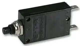
Illustrative purposes only

2-5700-IG1-P10-DD-000040 7A
Thermal Circuit Breaker, 2-5700 Series, 7 A, 1 Pole, 28 V, 250 V, Panel
⚠️ Reference pricing provided. In case of supply shortages, we will connect you with our trusted procurement partners to ensure your project's continuity.
- Manufacturer: ETA
- Product type: Thermal Circuit Breakers
- Product Range:2-5700 Series; Current Rating:7A; No. of Poles:1 Pole; Voltage Rating V DC:28VDC; Voltage Rating VAC:250VAC; Circuit Breaker Mounting:Panel; SVHC:No SVHC (15-Jan-2018); Approval Bodies:
- No. of Poles: 1 Pole
- Product Range: 2-5700 Series
- Current Rating: 7A
- Voltage Rating VAC: 250V
- Voltage Rating VDC: 28V
- Circuit Breaker Mounting: Panel
| Delivery and price | |
|---|---|
| Units per pack | 20 |
| Price | 23.29 € |
| Current stock | 25+ |
| Lead time | 30 days |
Datasheet

**Thermal Overcurrent Circuit Breakers 2-5000/2-5700-...**

**1**

## **Description**

Single pole thermal circuit breaker with press-to-reset, tease-free, trip-free, snap action mechanism. Type 2-5000 is available with optional manual release (-H), type 2-5700 can be supplied as a pushpush switch/circuit breaker (R-type TO CBE to EN 60934 in press-toreset configuration; M-type when fitted with manual release -H; S- type with push-push operation). Fitted with flange or threadneck for panel mounting. Options include an additional unprotected circuit tap (-A3). Approved to CBE standard EN 60934 (IEC 60934).

## **Typical applications**

Motors, transformers, solenoids, battery chargers, power supplies, appliances, machinery, extra low voltage systems.

## **Ordering information**

## **Type No.**

**==> picture [247 x 500] intentionally omitted <==**

**----- Start of picture text -----**<br>
|||||||||||
|---|---|---|---|---|---|---|---|---|---|
|2-5000|flange mounting|
|2-5700|threadneck panel mounting|
|(hardware bulk shipped)|
|Threadneck design – type 2-5700 only|
|iG1|moulded threadneck 3/8"-27UNS-2A|
|iG2|moulded threadneck M12x1|
|Terminal design|
|P10|blade terminals 6.3-0.8 mm (QC .250)|
|K10|screw terminals M4x6|
|Shunt terminal (optional) -P10 only|
|A3|shunt terminal (up to IN|2.5 A/6 A max. load)|
|Manual release (optional)|
|H|manual release facility|(type 2-5000 only)|
|DD|push to release/push to reset (type 2-5700 only)|
|Current ratings|
|0.05...25 A|
|=|
|2-5700 - iG1 -|P10 -|.. -|DD -|8 A|ordering example|
|The exact part number required can be built up from the table of choices shown|
|above. Ordering references for optional features should be omitted if not required.|
|Standard current ratings and typical internal resistance values|
|Current|Internal|Current|Internal|
|rating|(A)|resistance (|Ω|)|rating|(A)|resistance (|Ω|)|
|0.05|280|3|0.1|
|0.08|100|3.5|0.06|
|0.1|110|4|0.06|
|0.2|29|4.5|0.05|
|0.3|14|5|0.05|
|0.4|7|6|0.02|
|0.5|4.9|7|0.02|
|0.6|3.4|8|0.02|
|0.7|2.5|10|< 0.02|
|0.8|1.8|12|< 0.02|
|1|1.2|13|< 0.02|
|1.2|0.8|15|< 0.02|
|1.5|0.6|16|< 0.02|
|1.8|0.4|20|< 0.02|
|2|0.3|22|< 0.02|
|2.5|0.2|25|< 0.02|

**----- End of picture text -----**<br>


**2-5000-...                        2-5700-...**

## **Technical data**

**==> picture [250 x 345] intentionally omitted <==**

**----- Start of picture text -----**<br>
|||||
|---|---|---|---|
|Voltage rating|AC 250 V; DC 28 V|
|(UL: AC 250 V; DC 50 V)|
|Current rating range|0.05...25 A|
|Typical life                        5,000 operations at 2 x IN|
|Ambient temperature|-20...+60 °C  (-4...+140 °F)|
|Insulation co-ordination|rated impulse|pollution|
|(IEC 60664 and 60664 A)|withstand voltage|degree|
|2.5 kV|2|
|reinforced insulation in operating area|
|Dielectric strength|
|(IEC 60664 and 60664A)   test voltage|
|operating area|AC 3,000 V|
|Insulation resistance|> 100 M|Ω|(DC 500 V)|
|Interrupting capacity Icn|0.05...2.5 A|8 x IN|
|3...  5 A|20 x IN|
|6...12 A|200 A|
|(higher interrupting capacity|
|available to special order)|
|13...25 A|400 A|
|Interrupting capacity|IN|UN|
|(UL 1077)|0.05...20 A       AC 250 V   2,000 A|
|0.05...25 A|DC   50 V|2,000 A|
|Degree of protection|operating area IP40|
|(IEC 60529/DIN 40050)|terminal area IP00|
|Vibration                           8 g (57-500 Hz) ±0.61 mm (10-57 Hz),|
|to IEC 60068-2-6, test Fc,|
|10 frequency cycles/axis|
|Shock                               25 g (11 ms)|
|to IEC 60068-2-27, test Ea|
|Corrosion                          96 hours at 5 % salt mist,|
|to IEC 60068-2-11, test Ka|
|Humidity|240 hours at 95 % RH|
|to IEC 60068-2-3, test Ca|
|Mass                                approx. 29 g|

**----- End of picture text -----**<br>


## **Approvals**

**==> picture [229 x 91] intentionally omitted <==**

**----- Start of picture text -----**<br>
||||
|---|---|---|
|Authority|Voltage ratings|Current ratings|
|VDE (EN 60934)|AC 250 V; DC 28 V|0.05...25 A|
|CSA/ UL|AC 250 V; DC 50 V|0.05...20 A|
|Semko (EN 60934)|AC 250 V; DC 28 V|0,05...25 A|
|SEV|AC 250 V; DC 28 V|0,05...25 A|
|Type 2-5700 only:|
|LRoS|AC 250 V; DC 28 V|0.1  ...25 A|
|BV|AC 250 V; DC 28 V|0.2  ...25 A|

**----- End of picture text -----**<br>


Issue G

103

Germany (0 91 87) 10-0  -  USA (847) 827-7600  -  UK (01296) 420336 - www.e-t-a.com

## **Thermal Overcurrent Circuit Breakers 2-5000/2-5700-...**

## **Dimensions**

**==> picture [286 x 579] intentionally omitted <==**

**----- Start of picture text -----**<br>
2-5000-P10<br>ø9.5 ø13.5<br>.374 .531<br>1<br>A<br>1 4 3 2<br>19.8 14.5<br>.780 .571<br>31<br>blade terminal DIN 46244-A6.3-0.8<br>current rating in A 1.22 (QC .250)<br>2-5000-P10-A3<br>5 0.05...2.5 A<br>1 4 3 2<br>40<br>1.57<br>50 13<br>1.97 .512<br>2-5700-P10<br>iG1= [3] /8-27UNS-2A tightening torque max. 1 Nm<br>iG2=M12x1 tightening torque max. 1.5 Nm ø6.5<br>.256<br>A<br>1 4 3 2<br>blade terminal<br>19.8 DIN 46244-A6.3-0.8 14.5<br>.780 (QC .250) .571<br>29<br>1.14<br>D-shaped threadneck current rating in A for standard<br>(-DD version without push button marking)<br>mounting hole<br>5<br>SW 14<br>.551<br>iG1=ø9.6 -0.1<br>iG2=ø12.2 -0.1<br>iG1=.378 -.004<br>iG2=.480 -.004<br>ON OFF<br>12.2 .480 18.2 .717<br>5 .197 7 .276<br>44 1.73<br>10.4 .409<br>18.5 .728<br>ø4.5 .177<br>22.5 .886 16.5 .650 10 .394<br>OFF ON<br>46.5 1.83<br>10.4 .409<br>iG1=8.8 iG2=11.3 iG1=.346 iG2=.445 -0.1 -0.1 -.004 -.004<br>iG1=8.9  iG2=11.5  iG1=.350  iG2=. 453<br>**----- End of picture text -----**<br>


## **Terminal design**

**==> picture [249 x 114] intentionally omitted <==**

**----- Start of picture text -----**<br>
-P10-A3 -K10<br>0.05...2.5 A<br>1 4 3 2 1 4 3 2<br>13<br>.512 flat head screw M4x6 ISO1580<br>tightening torque 1.2 Nm<br>10.4 .409<br>**----- End of picture text -----**<br>


## **Installation drawings**

**==> picture [44 x 6] intentionally omitted <==**

**----- Start of picture text -----**<br>
2-5000-P10<br>**----- End of picture text -----**<br>


**==> picture [192 x 277] intentionally omitted <==**

**----- Start of picture text -----**<br>
operating area<br>A<br>1 4 3 2<br>mounting area<br>operating area<br>A<br>1 4 3 2<br>mounting area<br>1 1<br>.039 .039<br>max. 2.5 max .098<br>max. 2.5 max .098<br>25 .984 25 .984<br>**----- End of picture text -----**<br>


**==> picture [44 x 7] intentionally omitted <==**

**----- Start of picture text -----**<br>
2-5700-P10<br>**----- End of picture text -----**<br>


This is a metric design and millimeter dimensions take precedence ~~(~~[mm ] inch ~~)~~

Issue G

104

�[Germany (0 91 87) 10-0  -  USA (847) 827-7600  -  UK (01296) 420336 - www.e-t-a.com]

**Thermal Overcurrent Circuit Breakers 2-5000/2-5700-...**

**1**

## **Internal connection diagrams**

**==> picture [249 x 114] intentionally omitted <==**

**----- Start of picture text -----**<br>
0.05 ... 2.5 A 3 ... 25 A<br>(with or without shunt terminal) (without shunt terminal)<br>1 1<br>(3)<br>(-A3) 2 2<br>**----- End of picture text -----**<br>


## **Typical time/current characteristics at +23°C/+73.4°F**

**==> picture [249 x 316] intentionally omitted <==**

**----- Start of picture text -----**<br>
10000<br>0.05 - 2.5 A<br>3 - 25 A<br>1000<br>100<br>10<br>1<br>0.1<br>1 2 4 6 8 10 20 40<br>… times rated current<br>The time/current characteristic curve depends on the ambient temperature<br>prevailing. In order to eliminate nuisance tripping, please multiply the circuit<br>breaker current ratings by the derating factor shown below. See also<br>section 9 – Technical information.<br>Ambient temperature °F    -4 +14 +32   +73.4 +104 +122 +140<br>°C    -20 -10  0 +23 +40 +50 +60<br>Derating factor  0.76 0.84 0.92 1 1.08 1.16  1.24<br>Trip time in seconds<br>**----- End of picture text -----**<br>


This is a metric design and millimeter dimensions take precedence ~~(~~[mm ] inch ~~)~~

Issue G

105

�[Germany (0 91 87) 10-0  -  USA (847) 827-7600  -  UK (01296) 420336 - www.e-t-a.com]

**Thermal Overcurrent Circuit Breakers 2-5000/2-5700-...**

**1**

## **Accessories for types 2-5000 and 2-5700 with screw terminals -K10**

**==> picture [511 x 114] intentionally omitted <==**

**----- Start of picture text -----**<br>
Bus bar 176<br>Y 303 563 01 6.93<br>162<br>X<br>7 18 6.38 60 °<br>.276 .709<br>X<br>10 .394 M4<br>1.1 .043<br>2<br>.079<br>**----- End of picture text -----**<br>


## **Accessories for type 2-5000-...**

**==> picture [249 x 313] intentionally omitted <==**

**----- Start of picture text -----**<br>
Water splash cover, transparent Fixing plate<br>for push button  (IP64) Y 3012 056 02<br>Y 300 728 01<br>50<br>31.5 14.5<br>1.97<br>1.24 4.5 .57118 40<br>.177 .709 1.57<br>40<br>1.57<br>50<br>1.97<br>Rear terminal shroud, transparent  (IP64)<br>Y 300 476 01<br>12.5 29<br>.492 1.14<br>E - T - A<br>ø12 ø6<br>.472 .236<br>2.3 .091 0.5 .020<br>1.5 .059<br>.756<br>18.5 .728<br>49 1.93<br>19.2<br>**----- End of picture text -----**<br>


## **Accessories for type 2-5700-...**

**With 3/8" threadneck** (-iG1)

**Water splash cover, transparent Y 300 538 01 and knurled nut Y 300 628 01 X 200 799 01** (IP64)

**==> picture [43 x 7] intentionally omitted <==**

**----- Start of picture text -----**<br>
3/8-27 UNS-2B<br>**----- End of picture text -----**<br>


**Water splash cover, Hex nut with splash transparent with cover black with O ring special knurled nut X 210 739 01** (IP64) **X 200 798 02** (IP64) **transparent splash cover X 201 296 03** (IP64)

**==> picture [231 x 155] intentionally omitted <==**

**----- Start of picture text -----**<br>
3/8-27 UNS-2B 3/8-27 UNS-2B<br>Separate hardware<br>Hex nut Knurled nut<br>Y 300 192 01 Y 307 117 02<br>3/8-27 UNS-2B 3/8-27 UNS-2B<br>SW14 2.5 ø15 3<br>.551 .098 .591 .118<br>**----- End of picture text -----**<br>


**With M12 threadneck** (-iG2)

**Hex nut with splash cover, black X 201 296 01 without O ring** (IP64) **X 200 801 03 with O ring** (IP66) **Hex nut with splash cover, transparent X 200 801 08 with O ring** (IP66)

**Water splash cover, transparent with knurled nut and O ring X 210 663 01** (IP64)

**==> picture [485 x 150] intentionally omitted <==**

**----- Start of picture text -----**<br>
M12x1 M12x1<br>Hex nut Knurled nut<br>Y 300 116 02 Y 302 065 01<br>M12x1 M12x1 3.2<br>.126<br>This is a metric design and millimeter dimensions take precedence  (  [mm ] inch )<br>All dimensions without tolerances are for reference only. In the interest of improved design,performance and cost effectiveness the right to make changes in these specificationswithout notice is reserved.Product markings may not be exactly as the ordering codes. SW14.551 .0982.5 .669ø17 .020 x 450.5 x 45 °°<br>Errors and omissions excepted.<br>**----- End of picture text -----**<br>


Issue G

106

�[Germany (0 91 87) 10-0  -  USA (847) 827-7600  -  UK (01296) 420336 - www.e-t-a.com]
Updated at June 5, 2026
About Novapart
Novapart is a B2B electronic component broker specialising in stock shortages and cost reduction. We source hard-to-find parts and identify compliant alternatives across a catalogue of 410,000+ components from 500+ manufacturers.
Learn more →Stock Shortage Specialist
When a component is unavailable, discontinued or has an unacceptable lead time, we tap into our network of vetted European and Asian distributors to source what you need — without compromising on quality or traceability.
Request a quote →Compliant Alternatives
We identify pin-to-pin, electrically equivalent substitutes that meet the same certifications (RoHS, AEC-Q100, REACH) as your original specification — validated against datasheets, not just part numbers. Often at a lower cost.
BOM Analysis service →