


1SAM550000R1008
MOTOR STARTER, 3-PH, 37KW, 75A, 690V
- Manufacturer: ABB
- Product type: Motor Starters
- SVHC: To Be Advised
- No. of Poles: 3 Pole
- Power Rating: 37kW
- No. of Phases: Single Phase, Three Phase
- Product Range: MS495
- Current Rating: 75A
- IP / NEMA Rating: IP20
- Motor Starter Type: Manual Starter
- Supply Voltage Max: 690VAC
- Supply Voltage Min: 230VAC
| Delivery and price | |
|---|---|
| Units per pack | 1 |
| Price | 411.23 € |
| Current stock | 10+ |
| Lead time | 30 days |
Catalog
Motor protection and control Manual motor starters
**2**
2/0 | ABB
## Manual motor starters
**==> picture [288 x 737] intentionally omitted <==**
**----- Start of picture text -----**<br>
Benefits 2/2<br>Features 2/3<br>Overview 2/4<br>0.10 to 65 A – with thermal and electromagnetic protection 2<br>MS116 manual motor starters 2/6<br>MS132 manual motor starters 2/7<br>MS165 manual motor starters 2/8<br>0.16 to 65 A – with electromagnetic protection<br>MO132 manual motor starters magnetic only 2/9<br>MO165 manual motor starters magnetic only 2/10<br>0.10 to 25 A – with thermal and electromagnetic protection<br>MS132-T circuit breakers for transformer protection 2/11<br>Technical data<br>MS116, MS132, MS165, MO132, MO165, MS132-T 2/12<br>Main accessories<br>MS116, MS132, MS165, MO132, MO165, MS132-T 2/22<br>MS116, MS132, MS165, MO132, MO165 2/27<br>MS116, MS132, MO132, MS132-T 2/28<br>MS165, MO165 2/29<br>MS116, MS132, MS165, MO132, MO165 2/30<br>MS116, MS132, MO132 2/31<br>22 to 100 A – with thermal and electromagnetic protection<br>MS450, MS495, MS497 manual motor starters 2/32<br>Technical data<br>MS450, MS495, MS497 manual motor starters 2/33<br>32 to 100 A – with electromagnetic protection<br>MO450, MO495, MO496 manual motor starters magnetic only 2/36<br>Technical data<br>MO450, MO495, MO496 manual motor starters magnetic only 2/37<br>Main accessories<br>MS45x, MS49x, MO45x, MO49x manual motor starters 2/40<br>0.10 to 25 A – with thermal and electromagnetic protection<br>MS325 manual motor starters 2/46<br>0.4 to 25 A – with electromagnetic protection<br>MO325 manual motor starters magnetic only 2/47<br>Technical data<br>MS325, MO325 manual motor starters 2/48<br>MS325 manual motor starters 2/49<br>MS325, MO325 manual motor starters 2/50<br>Main accessories<br>MS325, MO325 manual motor starters 2/51<br>General accessories<br>MS116, MS132, MO132, MS4xx, MO4xx, MS325, MO325 2/55<br>2CDC131068C0201<br>**----- End of picture text -----**<br>
ABB | 2/1
**2**
## Manual motor starters Benefits
Manual motor starters (MMS) are protection devices for the main circuit. They combine motor control and protection in a single device. MMS are used mainly to switch motors manually ON/OFF and protect them and the installation fuse-less against short-circuit, overload and phase failures. Fuse-less protection with a manual motor starter saves costs, space and ensures a quick reaction under short-circuit condition, by switching off the motor within milliseconds.
Safe, compact, and cost-saving solution
Various motor protection functions in one device
- Overload
## Comprehensive accessory range
Manual motor starters can be equipped with busbars, auxiliary contacts, signalling contacts, undervoltage releases and shunt trips. Moreover it is possible to order IP65 (UL/CSA Type 12) door mounting kits, IP65 (UL/CSA Type 12) enclosures and shafts for doors.
MS116, MS132, MS165, MO132, MO165 and MS132-T share almost the same accessory range. Customers can optimize administration costs and inventory costs through reduced number of order codes by benefiting from a compatible range of accessories.
- Short-circuit
- Phase loss sensitivity
Efficient planning and installation perfectly matching the ABB contactor family, leads to high flexibility and increased exchangeability. Simple connecting links ensure the electrical and mechanical connection.
Products range for different applications available
Manual motor starters with busbar connection
- Short-circuit breaking capacity up to 100 kA
- Magnetic-only devices (only short-circuit protection)
- Selected types are certified according to ATEX
- Special version for transformer protection
The manual motor starter range is compatible with all major national and international standards.
Product range
Direct-on-line starters
Accessory range
Door mounting kits
2/2 | ABB
**2**
## Manual motor starters Features
## Features
- Manual control
- Disconnect function
- Handle can be locked in the off position
- Remote control via undervoltage release or shunt trip
- Trip indication
- Temperature compensation
- Magnetic trip indication for several types available (MS132, MS165, and MS132-T)
- One product family in 45 mm width (MS116, MS132, MO132, and MS132-T)
- Setting ranges from 0.1 up to 65 A (MS116, MS132, MS165, MO132, and MO165)
- Short-circuit service breaking capacity ICS up to 100 kA
- Adjustable current setting
- 1 Terminals (1L1, 3L2, 5L3)
- 2 Switch position TRIP
- 3 Lockable handle
- 4 Test function
- 1 Clear trip indication
- 2 Handle in TRIP position
- 3 Optical indication for short-circuit
- 4 Easy locking
- 5 Status indication for short-circuit
- 6 Current setting range
- 7 Terminals 2T1, 4T2, 6T3
**==> picture [149 x 8] intentionally omitted <==**
**----- Start of picture text -----**<br>
Magnetic tripping Thermal tripping<br>**----- End of picture text -----**<br>
Features of type MS132
**==> picture [5 x 10⁵] intentionally omitted <==**
**----- Start of picture text -----**<br>
11<br>2<br>3<br>4<br>5<br>6<br>7<br>**----- End of picture text -----**<br>
**==> picture [253 x 108] intentionally omitted <==**
**----- Start of picture text -----**<br>
1<br>2<br>) )<br>The ai Tr Wai<br>al i al i<br>2 4<br>3<br>**----- End of picture text -----**<br>
TRIP indication
ABB | 2/3
**2**
## Manual motor starters Overview
|Type|MS116|MS132|MS165|MS450|MS495|MS497|
|---|---|---|---|---|---|---|
|Thermal and electromagnetic<br>protection|Yes|Yes|Yes|Yes|Yes||
|Electromagnetic protection|-|-|-|-|-||
|Phase loss sensitivity|Yes|Yes|Yes|Yes|Yes||
|Switch position|ON/OFF|ON/OFF/TRIP|ON/OFF/TRIP|ON/OFF/TRIP|ON/OFF/TRIP||
|Magnetic trip indication|-|Yes|Yes|-|-||
|Lockable handle without<br>accessories|-|Yes|Yes|Yes|Yes||
|Disconnectingfeature|Yes|Yes|Yes|Yes|Yes||
|Width|45 mm|45 mm|55 mm|55 mm|70 mm||
|Rated operational current Ie|0.16 ... 32 A|0.16 ... 32 A|16 ... 65 A|40 ... 50 A|63 ... 100 A|32 ... 100 A|
|Settingrange|0.1 ... 32 A|0.1 ... 32 A|10 ... 65 A|28 ... 50 A|45 ... 100 A|22 ... 100 A|
|Ambient air temperature|-25 ... +55 °C *)|-25 ... +60 °C *)|-20 ... +60 °C *)|-20 ... +60 °C *)|-20 ... +60 °C *)||
*[)] Compensated
Table for short-circuit ratings for 400/415 V
|Rated operational<br>power|Setting range for<br>thermal release|Type|Short-circuit<br>breaking capacity<br>Icu<br>Ics|Short-circuit<br>breaking capacity<br>Icu<br>Ics|Type|Short-circuit<br>breaking capacity<br>Icu<br>Ics|Short-circuit<br>breaking capacity<br>Icu<br>Ics|Type|
|---|---|---|---|---|---|---|---|---|
|0.03 kW1)|0.1 ... 0.16 A|MS116-0.16|50 kA|50 kA|MS132-0.16|100 kA|100 kA|MS325-0.16|
|0.06 kW|0.16 ... 0.25 A|MS116-0.25|50 kA|50 kA|MS132-0.25|100 kA|100 kA|MS325-0.25|
|0.09 kW|0.25 ... 0.4 A|MS116-0.4|50 kA|50 kA|MS132-0.4|100 kA|100 kA|MS325-0.4|
|0.18 kW|0.4 ... 0.63 A|MS116-0.63|50 kA|50 kA|MS132-0.63|100 kA|100 kA|MS325-0.63|
|0.25 kW|0.63 ... 1.0 A|MS116-1.0|50 kA|50 kA|MS132-1.0|100 kA|100 kA|MS325-1|
|0.55 kW|1.0 ... 1.6 A|MS116-1.6|50 kA|50 kA|MS132-1.6|100 kA|100 kA|MS325-1.6|
|0.75 kW|1.6 ... 2.5 A|MS116-2.5|50 kA|50 kA|MS132-2.5|100 kA|100 kA|MS325-2.5|
|1.5 kW|2.5 ... 4.0 A|MS116-4.0|50 kA|50 kA|MS132-4.0|100 kA|100 kA|MS325-4|
|2.2 kW|4.0 ... 6.3 A|MS116-6.3|50 kA|50 kA|MS132-6.3|100 kA|100 kA|MS325-6.3|
|4.0 kW|6.3 ... 10 A|MS116-10|50 kA|50 kA|MS132-10|100 kA|100 kA|MS325-9|
|5.5 kW|8 ... 12 A|MS116-12|25 kA|25 kA|MS132-12|100 kA|100 kA|MS325-12.5|
|7.5 kW|10 ... 16 A|MS116-16|16 kA|16 kA|MS132-16 /<br>MS165-16|100 kA|100 kA|MS325-16|
|7.5 kW|14 ... 20 A||||MS165-20|100 kA|100 kA||
|7.5 kW|16 ... 20 A|MS116-20|15 kA|10 kA|MS132-20|100 kA|100 kA|MS325-20|
|11 kW|18 ... 25 A||||MS165-25|100 kA|100 kA||
|11 kW|20 ... 25 A|MS116-25|15 kA|10 kA|MS132-25|50 kA|50 kA|MS325-25|
|15 kW|25 ... 32 A|MS116-32|10 kA|10 kA|MS132-32|50 kA|25 kA||
|15 kW|22 ... 32 A||||MS497-32|100 kA|50 kA||
|15 kW|23 ... 32 A||||MS165-32|100 kA|75 kA||
|18.5 kW|28 ... 40 A|MS450-40|50 kA|25 kA|MS497-40|100 kA|50 kA||
|22 kW|30 ... 42 A||||MS165-42|50 kA|25 kA||
|22 kW|36 ... 45 A|MS450-45|50 kA|25 kA|||||
|22 kW|40 ... 50 A|MS450-50|50 kA|25 kA|MS497-50|100 kA|50 kA||
|22 kW|40 ... 54 A||||MS165-54|50 kA|25 kA||
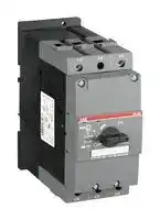
|30 kW|45 ... 63 A|MS495-63|50 kA|25 kA|MS497-63|100 kA|50 kA||
|30 kW|52 ... 65 A||||MS165-65|50 kA|25 kA||
|37 kW|57 ... 75 A|MS495-75|50 kA|25 kA|MS497-75|100 kA|50 kA||
|45 kW|70 ... 90 A|MS495-90|50 kA|25 kA|MS497-90|100 kA|50 kA||
|55 kW|80 ... 100 A|MS495-100|50 kA|25 kA|MS497-100|100 kA|50 kA||
1) 690 V
2/4 | ABB
**2**
|MO132|MO165|MO450|MO495|MO496|MO325|MS132-T|
|---|---|---|---|---|---|---|
|-|-|-|-||-|Yes|
|Yes|Yes|Yes|Yes||Yes|-|
|-|-|-|-||-|Yes|
|ON/OFF/TRIP|ON/OFF/TRIP|ON/OFF/TRIP|ON/OFF/TRIP||ON/OFF|ON/OFF/TRIP|
|-|-|-|-||-|Yes|
|Yes|Yes|Yes|Yes||-|Yes|
|Yes|Yes|Yes|Yes||Yes|Yes|
|45 mm|55 mm|55 mm|70 mm||54 mm|45 mm|
|0.16 ... 32 A|16 ... 65 A|40 ... 50 A|63 ... 100 A|32 ... 100 A|0.4 ... 25 A|0.16 ... 32 A|
|-|-|-|-||-|0.1 ... 25 A|
|-25 ... +60 °C|-25 ... +60 °C|-20 ... +60 °C|-20 ... +60 °C||-25 ... +50 °C|-25 ... +60 °C *)|
|Standard range<br>MO132, MO450, MO495|Standard range<br>MO132, MO450, MO495|Standard range<br>MO132, MO450, MO495|Performance range<br>MO132, MO165, MO496|Performance range<br>MO132, MO165, MO496|Performance range<br>MO132, MO165, MO496|Modular DIN rail design<br>MO325|Modular DIN rail design<br>MO325|Transformer protection<br>MS132-T|Transformer protection<br>MS132-T|
|---|---|---|---|---|---|---|---|---|---|
|||||||||||
|Type|Short-circuit<br>breaking capacity<br>Icu<br>Ics||Type|Short-circuit<br>breaking capacity<br>Icu<br>Ics||Type|Short-circuit<br>breaking capacity<br>Ics/ Icu|Type|Short-circuit<br>breaking capacity<br>Ics/ Icu|
|MO132-0.16|100 kA|100 kA|MO132-0.16|100 kA|100 kA||100 kA|MS132-0.16T|100 kA|
|MO132-0.25|100 kA|100 kA|MO132-0.25|100 kA|100 kA||100 kA|MS132-0.25T|100 kA|
|MO132-0.4|100 kA|100 kA|MO132-0.4|100 kA|100 kA|MO325-0.4|100 kA|MS132-0.4T|100 kA|
|MO132-0.63|100 kA|100 kA|MO132-0.63|100 kA|100 kA|MO325-0.63|100 kA|MS132-0.63T|100 kA|
|MO132-1.0|100 kA|100 kA|MO132-1.0|100 kA|100 kA|MO325-1|100 kA|MS132-1.0T|100 kA|
|MO132-1.6|100 kA|100 kA|MO132-1.6|100 kA|100 kA|MO325-1.6|100 kA|MS132-1.6T|100 kA|
|MO132-2.5|100 kA|100 kA|MO132-2.5|100 kA|100 kA|MO325-2.5|100 kA|MS132-2.5T|100 kA|
|MO132-4.0|100 kA|100 kA|MO132-4.0|100 kA|100 kA|MO325-4|100 kA|MS132-4.0T|100 kA|
|MO132-6.3|100 kA|100 kA|MO132-6.3|100 kA|100 kA|MO325-6.3|100 kA|MS132-6.3T|100 kA|
|MO132-10|100 kA|100 kA|MO132-10|100 kA|100 kA|MO325-9|100 kA|MS132-10T|100 kA|
|MO132-12|100 kA|100 kA|MO132-12|100 kA|100 kA|MO325-12.5|75 kA|MS132-12T|100 kA|
|MO132-16|100 kA|100 kA|MO132-16 /<br>MO165-16|100 kA|100 kA|MO325-16|60 kA|MS132-16T|100 kA|
||||MO165-20|100 kA|100 kA|||||
|MO132-20|100 kA|100 kA|MO132-20|100 kA|100 kA|MO325-20|55 kA|MS132-20T|100 kA|
|||||||||||
|MO132-25|50 kA|50 kA|MO132-25 /<br>MO165-25|50 kA /<br>100 kA|50 kA /<br>100 kA|MO325-25|50 kA|MS132-25T|50 kA|
|MO132-32|50 kA|25 kA|MO132-32|50 kA|25 kA|||Transformer protection:<br>The instantaneous short-circuit current<br>setting is 20 times the rated operational<br>current.||
||||MO496-32|100 kA|50 kA|||||
||||MO165-32|100 kA|50 kA|||||
|MO450-40|50 kA|25 kA|MO496-40|100 kA|50 kA|||||
||||MO165-42|50 kA|25 kA|||||
|MO450-45|50 kA|25 kA||||||||
|MO450-50|50 kA|25 kA|MO496-50|100 kA|50 kA|||||
||||MO165-54|50 kA|25 kA|||||
|MO495-63|50 kA|25 kA|MO496-63|100 kA|50 kA|||||
||||MO165-65|50 kA|25 kA|||||
|MO495-75|50 kA|25 kA|MO496-75|100 kA|50 kA|||||
|MO495-90|50 kA|25 kA|MO496-90|100 kA|50 kA|||||
|MO495-100|50 kA|25 kA|MO496-100|100 kA|50 kA|||||
ABB | 2/5
**2**
## 0.10 to 65 A – with thermal and electromagnetic protection MS116 manual motor starters
## Description
**==> picture [4 x 37] intentionally omitted <==**
**----- Start of picture text -----**<br>
2CDC241010F0011<br>**----- End of picture text -----**<br>
MS116-16
**==> picture [4 x 37] intentionally omitted <==**
**----- Start of picture text -----**<br>
2CDC241001F0011<br>**----- End of picture text -----**<br>
MS116-25
**==> picture [82 x 178] intentionally omitted <==**
**----- Start of picture text -----**<br>
MS116-0.16-HKF1-11<br>‘wh<br>MS116-32-HKF1-11<br>2CDC241013F0011<br>2CDC241012F0011<br>**----- End of picture text -----**<br>
MS116 is a compact and economic range for motor protection up to 15 kW (400 V) / 32 A in width of 45 mm. Further features are the build-in disconnect function, temperature compensation, trip-free mechanism and a rotary handle with a clear switch position indication. The manual motor starter is suitable for three- and single-phase applications. Auxiliary contacts, signaling contacts, undervoltage releases, shunt trips, power in-feed blocks and locking devices for protection against unauthorized changes are available as accessory. These are suitable throughout the MS116/MS132/MS165-range.
## Ordering details
|Rated<br>operational<br>power<br>400 V<br>AC-3<br>kW|operational<br>Setting<br>range<br>A|Short-circuit<br>breaking<br>capacity ICSat<br>400 V AC<br>kA|Rated instan-<br>taneous short-<br>circuit current<br>setting li<br>A|Type|Order code||Weight<br>(1 pc)<br>kg|
|---|---|---|---|---|---|---|---|
|0.032)|0.10 ... 0.16|50|2.001)|MS116-0.16|1SAM250000R1001||0.225|
|0.06|0.16 ... 0.25 50|0.16 ... 0.25 50|3.101)|MS116-0.25|1SAM250000R1002||0.225|
|0.09|0.25 ... 0.40|50|5.001)|MS116-0.4|1SAM250000R1003||0.225|
|0.18|0.40 ... 0.63 50|0.40 ... 0.63 50|7.901)|MS116-0.63|1SAM250000R1004||0.225|
|0.25|0.63 ... 1.00 50|0.63 ... 1.00 50|12.51)|MS116-1.0|1SAM250000R1005||0.225|
|0.55|1.00 ... 1.60 50|1.00 ... 1.60 50|20.01)|MS116-1.6|1SAM250000R1006||0.265|
|0.75|1.60 ... 2.50 50|1.60 ... 2.50 50|31.31)|MS116-2.5|1SAM250000R1007||0.265|
|1.50|2.50 ... 4.00 50|2.50 ... 4.00 50|50.0|MS116-4.0|1SAM250000R1008||0.265|
|2.20|4.00 ... 6.30 50|4.00 ... 6.30 50|78.8|MS116-6.3|1SAM250000R1009||0.265|
|4.00|6.30 ... 10.0 50|6.30 ... 10.0 50|150|MS116-10|1SAM250000R1010||0.265|
|5.50|8.00 ... 12.0 25|8.00 ... 12.0 25|180|MS116-12|1SAM250000R1012||0.265|
|7.50|10.0 ... 16.0 16|10.0 ... 16.0 16|240|MS116-16|1SAM250000R1011||0.265|
|7.50|16.0 ... 20.0|10|300|MS116-20|1SAM250000R1013||0.310|
|11.0|20.0 ... 25.0|10|375|MS116-25|1SAM250000R1014||0.310|
|15.0|25.0 ... 32.0|10|480|MS116-32|1SAM250000R1015||0.310|
|0.032)|0.10 ... 0.16|50|2.001)|MS116-0.16-HKF1-11|1SAM250005R1001||0.240|
|0.06|0.16 ... 0.25 50|0.16 ... 0.25 50|3.101)|MS116-0.25-HKF1-11|1SAM250005R1002||0.240|
|0.09|0.25 ... 0.40|50|5.001)|MS116-0.4-HKF1-11|1SAM250005R1003||0.240|
|0.18|0.40 ... 0.63 50|0.40 ... 0.63 50|7.901)|MS116-0.63-HKF1-11|1SAM250005R1004||0.240|
|.25|0.63... 1.00|50|12.51)|MS116-1.0-HKF1-11|1SAM250005R1005||0.240|
|0.55|1.00 ... 1.60 50|1.00 ... 1.60 50|20.01)|MS116-1.6-HKF1-11|1SAM250005R1006||0.280|
|0.75|1.60 ... 2.50 50|1.60 ... 2.50 50|31.31)|MS116-2.5-HKF1-11|1SAM250005R1007||0.280|
|1.50|2.50 ... 4.00 50|2.50 ... 4.00 50|50.0|MS116-4.0-HKF1-11|1SAM250005R1008||0.280|
|2.20|4.00 ... 6.30 50|4.00 ... 6.30 50|78.8|MS116-6.3-HKF1-11|1SAM250005R1009||0.280|
|4.00|6.30 ... 10.0 50|6.30 ... 10.0 50|150|MS116-10.0-HKF1-11|1SAM250005R1010||0.280|
|5.50|8.00 ... 12.0 25|8.00 ... 12.0 25|180|MS116-12.0-HKF1-11|1SAM250005R1012||0.280|
|7.50|10.0 ... 16.0 16|10.0 ... 16.0 16|240|MS116-16.0-HKF1-11|1SAM250005R1011||0.280|
|7.50|16.0 ... 20.0|10|300|MS116-20-HKF1-11|1SAM250005R1013||0.326|
|11.0|20.0 ... 25.0|10|375|MS116-25-HKF1-11|1SAM250005R1014||0.326|
|15.0|25.0 ... 32.0|10|480|MS116-32-HKF1-11|1SAM250005R1015||0.326|
Note: Manual motor starters should always be selected so that the actual motor current is within the setting range. 1) The data is valid for products, produced after week 34, 2014.
2) 690 V
Main dimensions mm, _inches_
**==> picture [390 x 122] intentionally omitted <==**
**----- Start of picture text -----**<br>
79.9 3.15"<br>1.5 0.06" 70 80.1 2.76"3.15" 1.5 0.06" 5.5 0.22" 43.3 69.8 1.7" 2.75"<br>5.5 0.22" 43.5 1.71"<br>a =| 7 i: on F i °t<br>1 c_ ] oe I @ 5<br>14 0.55" 14 0.55" LH B I<br>c 45 1.77" : 14 0.55" 14 0.55"<br>MS116 ≤ 16 A & MS116-HKF1-11 ≤ 16 A MS116 ≥ 20 A & MS116-HKF1-11 ≥ 20 A<br>0.07"<br>0.07"<br>90 3.54" 1.7 1.1" 2.95" 75 35 1.38" 1.77" 45 57.8 2.3" 97.8 3.85" 1.7 1.1" 2.95" 75 35 1.38" 1.77" 45 2.3"<br>27.5 57.8<br>2CDC242002F0010 27.5 2CDC242001F0011<br>**----- End of picture text -----**<br>
MS116 ≤ 16 A & MS116-HKF1-11 ≤ 16 A
2/6 | ABB
**2**
## 0.10 to 65 A – with thermal and electromagnetic protection MS132 manual motor starters
## Description
**==> picture [97 x 37] intentionally omitted <==**
**----- Start of picture text -----**<br>
7<br>a—<br>1SBC101232F0010<br>**----- End of picture text -----**<br>
MS132-10
**==> picture [4 x 37] intentionally omitted <==**
**----- Start of picture text -----**<br>
2CDC241001F0011<br>**----- End of picture text -----**<br>
MS132-32
**==> picture [4 x 160] intentionally omitted <==**
**----- Start of picture text -----**<br>
2CDC241014F0011<br>2CDC241015F0011<br>**----- End of picture text -----**<br>
MS132-0.16-HKF1-11
MS132-32-HKF1-11
MS132 is a compact and powerful range for motor protection up to 15 kW (400 V) / 32 A in width of 45 mm. This type has also a clear and reliable indication of fault in a separate window in the event of short-circuit tripping. Further features are the build-in disconnect function, temperature compensation, trip-free mechanism and a rotary handle with a clear switch position indication. The manual motor starter is suitable for three- and single-phase applications. The handle is lockable to protect against unauthorized changes. Auxiliary contacts, signaling contacts, undervoltage releases, shunt trips, power in-feed blocks are available as accessory. These are suitable throughout the MS116/MS132/MS165-range.
## Ordering details
|Rated<br>operational<br>power<br>400 V<br>AC-3<br>kW|operational<br>Setting<br>range<br>A|Short-circuit<br>breaking<br>capacity ICSat<br>400 V AC<br>kA|Rated instan-<br>taneous short-<br>circuit current<br>setting li<br>A|Type|Order code||Weight<br>(1 pc)<br>kg|
|---|---|---|---|---|---|---|---|
|0.032)|0.10 … 0.16|100|2.001)|MS132-0.16|1SAM350000R1001||0.215|
|0.06|0.16 … 0.25|100|3.101)|MS132-0.25|1SAM350000R1002||0.215|
|0.09|0.25 … 0.40|100|5.001)|MS132-0.4|1SAM350000R1003||0.215|
|0.18|0.40 … 0.63|100|7.901)|MS132-0.63|1SAM350000R1004||0.215|
|0.25|0.63 … 1.00|100|12.51)|MS132-1.0|1SAM350000R1005||0.215|
|0.55|1.00 … 1.60|100|20.01)|MS132-1.6|1SAM350000R1006||0.265|
|0.75|1.60 … 2.50|100|31.31)|MS132-2.5|1SAM350000R1007||0.265|
|1.50|2.50 … 4.00|100|50.0|MS132-4.0|1SAM350000R1008||0.265|
|2.20|4.00 … 6.30|100|78.8|MS132-6.3|1SAM350000R1009||0.265|
|4.00|6.30 … 10.0|100|150|MS132-10|1SAM350000R1010||0.265|
|5.50|8.00 … 12.0|100|180|MS132-12|1SAM350000R1012||0.310|
|7.50|10.0 … 16.0|100|240|MS132-16|1SAM350000R1011||0.310|
|7.50|16.0 … 20.0|100|300|MS132-20|1SAM350000R1013||0.310|
|11.0|20.0 … 25.0|50|375|MS132-25|1SAM350000R1014||0.310|
|15.0|25.0 … 32.0|25|480|MS132-32|1SAM350000R1015||0.310|
|0.032)|0.10 ... 0.16|100|2.001)|MS132-0.16-HKF1-11|1SAM350005R1001||0.231|
|0.06<br>~~—~~|0.16 ... 0.25<br>~~—"Le~~|100<br>~~"Le~~|3.101)<br>~~"Le~~|MS132-0.25-HKF1-11<br>~~"Le~~|1SAM350005R1002<br>~~"Le~~|~~"Le~~|0.231<br>~~"Le~~|
|0.09<br>~~—~~|0.25 ... 0.40<br>~~—"Le~~|100<br>~~"Le~~|5.001)<br>~~"Le~~|MS132-0.4-HKF1-11<br>~~"Le~~|1SAM350005R1003<br>~~"Le~~|~~"Le~~|0.231<br>~~"Le~~|
|0.18<br>~~—~~|0.40 ... 0.63<br>~~—"Le~~|100<br>~~"Le~~|7.901)<br>~~"Le~~|MS132-0.63-HKF1-11<br>~~"Le~~|1SAM350005R1004<br>~~"Le~~|~~"Le~~|0.231<br>~~"Le~~|
|0.25|0.63... 1.00|100|12.5 1)|MS132-1.0-HKF1-11|1SAM350005R1005||0.231|
|0.55|1.00 ... 1.60|100|20.01)|MS132-1.6-HKF1-11|1SAM350005R1006||0.281|
|0.75|1.60 ... 2.50|100|31.31)|MS132-2.5-HKF1-11|1SAM350005R1007||0.281|
|1.50|2.50 ... 4.00|100|50.0|MS132-4.0-HKF1-11|1SAM350005R1008||0.281|
|2.20|4.00 ... 6.30|100|78.8|MS132-6.3-HKF1-11|1SAM350005R1009||0.281|
|4.00|6.30 ... 10.0|100|150|MS132-10.0-HKF1-11|1SAM350005R1010||0.281|
|5.50|8.00 ... 12.0|100|180|MS132-12.0-HKF1-11|1SAM350005R1012||0.326|
|7.50|10.0 ... 16.0|100|240|MS132-16.0-HKF1-11|1SAM350005R1011||0.326|
|7.50|16.0 ... 20.0|100|300|MS132-20-HKF1-11|1SAM350005R1013||0.326|
|11.0|20.0 ... 25.0|50|375|MS132-25-HKF1-11|1SAM350005R1014||0.326|
|15.0|25.0 ... 32.0|25|480|MS132-32-HKF1-11|1SAM350005R1015||0.326|
Note: Manual motor starters should always be selected so that the actual motor current is within the setting range. 1) The data is valid for products, produced after week 34, 2014.
2) 690 V
## Main dimensions mm, _inches_
**==> picture [353 x 119] intentionally omitted <==**
**----- Start of picture text -----**<br>
81.05 3.19"<br>81.25 3.2" 72.2 2.84"<br>72.4 2.85" 1.5 0.06" 5.5 0.22" 43.3 0.22"<br>1.5 0.06" 5.5 0.22" 43.5 1.71"<br>i— a a<br>TT i O ©<br>Lifer ams.<br>iN | | ESP o l )<br>@ 6 a rw , 4 }<br>ANT TTT |gl ©© |R STA C o ‘| @© :<br>14 0.55" 14 0.55" 14 0.55" 14 0.55"<br>i 45 1.77" { 45 1.77"<br>MS132 ≤ 10 A MS132 ≥ 12 A<br>0.1"<br> 3.54" 90 0.1" 1.7 2.95" 75 1.38" 35 1.77" 45" 3.85" 97.8 1.7 2.95" 75 1.38" 35 1.77" 45<br>2CDC242015F0009<br>**----- End of picture text -----**<br>
MS132 ≤ 10 A
ABB | 2/7
**2**
## 0.10 to 65 A – with thermal and electromagnetic protection MS165 manual motor starters
## Description
MS165-65
**==> picture [4 x 37] intentionally omitted <==**
**----- Start of picture text -----**<br>
2CDC241004V0015<br>**----- End of picture text -----**<br>
MS165 is a compact and powerful range for motor protection up to 30 kW (400 V) / 65 A in width of 55 mm. This type has also a clear and reliable indication of fault in a separate window in the event of short-circuit tripping. Further features are the build-in disconnect function, temperature compensation, trip-free mechanism and a rotary handle with a clear switch position indication. The manual motor starter is suitable for three- and single-phase applications. The handle is lockable to protect against unauthorized changes. Auxiliary contacts, signaling contacts, undervoltage releases, shunt trips, power in-feed blocks are available as accessory. These are suitable throughout the MS116/MS132/MS165-range.
## Ordering details
|Ordering details||||||
|---|---|---|---|---|---|
|operational<br>Setting<br>range<br>A|Short-circuit<br>breaking<br>capacity ICSat<br>400 V AC<br>kA|Rated instan-<br>taneous short-<br>circuit current<br>setting li<br>A|Type|Order code||
|10 ... 16|100|240|MS165-16|1SAM451000R1011||
|14 ... 20|100|300|MS165-20|1SAM451000R1012||
|18 ... 25|100|375|MS165-25|1SAM451000R1013||
|23 ... 32|75|480|MS165-32|1SAM451000R1014||
|30 ... 42|25|630|MS165-42|1SAM451000R1015||
|40 ... 54|25|810|MS165-54|1SAM451000R1016||
|52 ... 65|25|975|MS165-65|1SAM451000R1017||
Note: Manual motor starters should always be selected so that the actual motor current is within the setting range.
Main dimensions mm, _inches_
**==> picture [199 x 134] intentionally omitted <==**
**----- Start of picture text -----**<br>
17.5 0.69" PT 55 2.17" 17.5 0.69" 5.5 0.22" 95.5 122.1 3.76" 4.81"<br>ill i;<br>(TT B oT<br>[ e c o °<br>e | ae3 a | 6 p<br>TOOT2 t y 8 qo<br>2.05 0.08" 93.5 3.68"<br>MS165<br>"0.07<br>1.75 "4.17 "5.62 "1.38 " 1.77 " 3.01<br>106 142.65 35 44.9 76.35<br>2CDC242001F0014<br>**----- End of picture text -----**<br>
2/8 | ABB
**2**
## 0.16 to 65 A – with electromagnetic protection MO132 manual motor starters magnetic only
## Description
Manual motor starters magnetic only are electromechanical protection devices for the main circuit. They are used mainly to switch motors manually ON/OFF and protect them fuse-less against short-circuit.
MO132-6.3
MO132-32
**==> picture [4 x 172] intentionally omitted <==**
**----- Start of picture text -----**<br>
2CDC241009F0011<br> 2CDC241008F0011<br>**----- End of picture text -----**<br>
Fuse-less protection with a manual motor starter saves costs, space and ensures a quick reaction under short-circuit condition, by switching off the motor within milliseconds. Fuse-less starter combinations are setup together with contactors and overload relays.
## Ordering details
|Rated<br>operational<br>power<br>400 V<br>AC-31)<br>kW|Rated<br>operational<br>current<br>A|Short-circuit<br>breaking<br>capacity ICSat<br>400 V AC<br>kA|Rated instan-<br>taneous short-<br>circuit current<br>setting li<br>A|Type|Order code||Weight<br>(1 pc)<br>kg|
|---|---|---|---|---|---|---|---|
|0.033)|0.16|100|2.002)|MO132-0.16|1SAM360000R1001||0.215|
|0.06|0.25|100|3.102)|MO132-0.25|1SAM360000R1002||0.215|
|0.09|0.40|100|5.002)|MO132-0.4|1SAM360000R1003||0.215|
|0.12|0.63|100|7.902)|MO132-0.63|1SAM360000R1004||0.215|
|0.25|1.0|100|12.52)|MO132-1.0|1SAM360000R1005||0.215|
|0.55|1.6|100|20.02)|MO132-1.6|1SAM360000R1006||0.265|
|0.75|2.5|100|31.32)|MO132-2.5|1SAM360000R1007||0.265|
|1.5|4.0|50|50.0|MO132-4.0|1SAM360000R1008||0.265|
|2.2|6.3|50|78.8|MO132-6.3|1SAM360000R1009||0.265|
|4.0|10|50|125|MO132-10|1SAM360000R1010||0.265|
|5.5|12|50|150|MO132-12|1SAM360000R1012||0.310|
|7.5|16|50|200|MO132-16|1SAM360000R1011||0.310|
|7.5|20|50|250|MO132-20|1SAM360000R1013||0.310|
|11|25|50|313|MO132-25|1SAM360000R1014||0.310|
|15|32|25|400|MO132-32|1SAM360000R1015||0.310|
- 1) For overload protection of motors, an appropriate thermal or electronic overload relay must be used
2) The data is valid for products, produced after week 34, 2014.
3) 690 V
Main dimensions mm, _inches_
**==> picture [392 x 135] intentionally omitted <==**
**----- Start of picture text -----**<br>
81.05 3.19"<br>81.25 3.2" 72.2 2.84"<br>72.4 2.85" 1.5 0.06" 5.5 0.22" 43.3 0.22"<br>1.5 0.06" 5.5 0.22" 43.5 1.71"<br>—is cr a | ld ° 4<br>4 ° 4 awe y L<br>p S a i SC) |<br>CCT GI] © Gy 4}<br>14 0.55" 14 0.55" 14 0.55" 14 0.55"<br>Co 45 1.77" y [| 45 1.77"<br>MO132 ≤ 10 A MO132 ≥ 12 A<br>0.1"<br> 0.1" 1.7<br> 3.54" 90 1.7 2.95" 75 1.38" 35 1.77" 45" 3.85" 97.8 2.95" 75 1.38" 35 1.77" 45<br>2CDC242005F0011 2CDC242006F0011<br>**----- End of picture text -----**<br>
ABB | 2/9
**2**
## 0.16 to 65 A – with electromagnetic protection MO165 manual motor starters magnetic only
## Description
Manual motor starters magnetic only are electromechanical protection devices for the main circuit. They are used mainly to switch motors manually ON/OFF and protect them fuse-less against short-circuit. Fuse-less protection with a manual motor starter saves costs, space and ensures a quick reaction under short-circuit condition, by switching off the motor within milliseconds. Fuse-less starter combinations are setup together with contactors and overload relays.
**==> picture [82 x 55] intentionally omitted <==**
**----- Start of picture text -----**<br>
MO165-65<br>2CDC241005V0015<br>**----- End of picture text -----**<br>
## Ordering details
|Ordering details|||||
|---|---|---|---|---|
|Short-circuit<br>breaking capacity<br>ICSat 400 V AC<br>kA|Rated instantane-<br>ous short-circuit<br>current setting li<br>A|Type|Order code||
|100|240|MO165-16|1SAM461000R1011||
|100|300|MO165-20|1SAM461000R1012||
|100|375|MO165-25|1SAM461000R1013||
|50|480|MO165-32|1SAM461000R1014||
|25|630|MO165-42|1SAM461000R1015||
|25|810|MO165-54|1SAM461000R1016||
|25|975|MO165-65|1SAM461000R1017||
Main dimensions mm, _inches_
**==> picture [202 x 134] intentionally omitted <==**
**----- Start of picture text -----**<br>
17.5 0.69" PT 55 2.17" 17.5 0.69" 5.5 0.22" 95.5 122.1 3.76" 4.81"<br>ill i;<br>VM : of<br>qi 6 6 ]<br>o i(__|l t f A&o fo | L7° eeot<br>TT CB e<br>a a —<br>2.05 0.08" 93.5 3.68"<br>M0165<br>"0.07<br>1.75 "4.17 "5.62 "1.38 1.77" " 3.01<br>106 142.65 35 44.9 76.35<br>2CDC242002F0014<br>**----- End of picture text -----**<br>
2/10 | ABB
**2**
## 0.10 to 25 A – with thermal and electromagnetic protection MS132-T circuit breakers for transformer protection
## Description
**==> picture [82 x 172] intentionally omitted <==**
**----- Start of picture text -----**<br>
“oat<br>MS132-10T<br>MS132-25T<br>2CDC241001F0014<br>2CDC241002F0014<br>**----- End of picture text -----**<br>
Circuit breakers for transformer protection are electro mechanical protection devices specially designed to protect control transformers on the primary side. They allow fuse-less protection against overload and shortcircuit, saving space and cost and ensuring a quick reaction under short-circuit condition by switching off the transformer within milliseconds. The short-circuit current setting is fixed to 20 times the operating current to handle the high inrush current generated by transformers. The device allows manual connection and disconnection of the transformer from the mains.
MS132-T is a 45 mm (width) compact and powerful range for transformer protection up to 12.5 kW (400 V) / 25 A. This type has also a clear and reliable indication of fault in a separate window in the event of shortcircuit tripping. Further features are the build-in disconnect function, temperature compensation, trip-free mechanism and a rotary handle with a clear switch position indication. The handle is lockable to protect against unauthorized changes. Auxiliary contacts, signaling contacts, undervoltage releases, shunt trips, power in-feed blocks are available as accessory. These are suitable throughout the MS116/MS132/MS165-range. Moreover ABB offers special accessories for fast single-phase setup.
## Ordering details
|Setting range<br>A|Short-circuit<br>breaking capacity<br>ICSat 400 V AC<br>kA|Rated instantane-<br>ous short-circuit<br>current setting li<br>A|Type|Order code||Weight<br>(1 pc)<br>kg|
|---|---|---|---|---|---|---|
|0.10 … 0.16|100|3.2|MS132-0.16T|1SAM340000R1001||0.215|
|0.16 … 0.25|100|5|MS132-0.25T|1SAM340000R1002||0.215|
|0.25 … 0.40|100|8|MS132-0.4T|1SAM340000R1003||0.215|
|0.40 … 0.63|100|12.6|MS132-0.63T|1SAM340000R1004||0.215|
|0.63 … 1.00|100|20|MS132-1.0T|1SAM340000R1005||0.215|
|1.00 … 1.60|100|32|MS132-1.6T|1SAM340000R1006||0.265|
|1.60 … 2.50|100|50|MS132-2.5T|1SAM340000R1007||0.265|
|2.50 … 4.00|100|80|MS132-4.0T|1SAM340000R1008||0.265|
|4.00 … 6.30|100|126|MS132-6.3T|1SAM340000R1009||0.265|
|6.30 … 10.0|100|200|MS132-10T|1SAM340000R1010||0.265|
|8.00 … 12.0|100|240|MS132-12T|1SAM340000R1012||0.310|
|10.0 … 16.0|100|320|MS132-16T|1SAM340000R1011||0.310|
|16.0 … 20.0|100|400|MS132-20T|1SAM340000R1013||0.310|
|20.0 … 25.0|50|500|MS132-25T|1SAM340000R1014||0.310|
Please check for single-phase equipment chapter Main accessories.
Main dimensions mm, _inches_
**==> picture [403 x 138] intentionally omitted <==**
**----- Start of picture text -----**<br>
81.05 3.19"<br>81.25 3.2" 72.2 2.84"<br>72.4 2.85" 1.5 0.06" 5.5 0.22" 43.3 0.22"<br>1.5 0.06" 5.5 0.22" 43.5 1.71"<br>+ —h =] |<br>TT TM iy °<br>:|<br>i<br>14 0.55" 14 0.55" 14 0.55" 14 0.55"<br>| 45 1.77" L 45 1.77" o<br>MS132T ≤ 10 A MS132T ≥ 12 A<br>0.1"<br> 3.54" 90 0.1" 1.7 2.95" 75 1.38" 35 1.77" 45" 3.85" 97.8 1.7 2.95" 75 1.38" 35 1.77" 45<br>2CDC242015F0009 2CDC242016F0009<br>2CDC131062C0201<br>**----- End of picture text -----**<br>
ABB | 2/11
**2**
## Technical data MS116, MS132, MS165, MO132, MO165, MS132-T
Main circuit – Utilization characteristics according to IEC/EN
**==> picture [527 x 232] intentionally omitted <==**
**----- Start of picture text -----**<br>
Type MS116 MS132 MS165 MO132 MO165 MS132-T<br>Standards IEC/EN 60947–2, IEC/EN 60947-4-1, IEC/EN 60947-1<br>Rated operational voltage Ue 690 V AC 690 V AC / 250 V DC 690 V AC 690 V AC 690 V AC 690 V AC<br>Rated frequency 50/60 Hz DC, 50/60 Hz 50/60 Hz 50/60 Hz 50/60 Hz 50/60 Hz<br>Trip class 10A 10 (10A for 1SA 10 - - 10<br>M350000R1001)<br>Number of poles 3<br>Duty time 100 %<br>Mechanical durability 100000 cycles 100000 cycles 50000 cycles 100000 cycles 50000 cycles 100000 cycles<br>Electrical durability up to 16 A 100000 cycles 50000 cycles 25000 cycles 50000 cycles 25000 cycles 50000 cycles<br>20 ... 65 A 50000 cycles 50000 cycles 25000 cycles 50000 cycles 25000 cycles 50000 cycles<br>Rated impulse withstand voltage U imp 6 kV 6 kV 8 kV 6 kV 8 kV 6 kV<br>Rated insulation voltage U i 690 V 690 V 1000 V 690 V 1000 V 690 V<br>Rated operational current I e See ordering details<br>Rated operational current DC-5 I3 conducting paths in series up to 250 Ve - See "Rated operational cur- - - - -<br>rent I e "<br>Rated instantaneous short-circuit current setting I i See ordering details<br>Rated service short-circuit breaking capacity I cs See table "Short-circuit breaking capacity and back-up fuses"<br>Rated ultimate short-circuit breaking capacity I cu See table "Short-circuit breaking capacity and back-up fuses"<br>Rated service short-circuit breaking capacity DC I3 conducting paths in series up to 250 V cs - 10 kA - - - -<br>**----- End of picture text -----**<br>
## Short-circuit breaking capacity and back-up fuses
lCS Rated service short-circuit breaking capacity
lCU Rated ultimate short-circuit breaking capacity ICC Prospective short-circuit current at installation location
Note: Maximum rated current of the back-up fuses if ICC > ICS
**==> picture [527 x 188] intentionally omitted <==**
**----- Start of picture text -----**<br>
Type 230 V AC 400 V AC 440 V AC 500 V AC 690 V AC<br>ICS ICU gG, aM ICS ICU gG, aM ICS ICU gG, aM ICS ICU gG, aM ICS ICU gG, aM<br>kA kA A kA kA A kA kA A kA kA A kA kA A<br>MS116-0.16<br>MS116-0.25<br>MS116-0.4<br>MS116-0.63 No back-up fuse required up to ICC = 30 kA<br>MS116-1.0<br>MS116-1.6 No back-up fuse required up to ICC = 50 kA<br>MS116-2.5 10 10 25 10 10 25 5 5 25<br>MS116-4.0 6 6 25 6 6 25 2 2 25<br>MS116-6.3 6 6 63 6 6 63 2 2 40<br>MS116-10 6 6 63 6 6 63 2 2 50<br>MS116-12 25 25 80 25 25 80 6 6 63 6 6 63 2 2 50<br>MS116-16 16 16 80 16 16 80 6 6 63 4 4 63 2 2 63<br>MS116-20 10 15 125 10 15 125 3 6 125 3 4 125 2 2 80<br>MS116-25 10 15 125 10 15 125 3 6 125 3 4 125 2 2 100<br>MS116-32 10 10 125 10 10 125 3 6 125 3 4 125 2 2 100<br>**----- End of picture text -----**<br>
MS116-10: No need for back-up fuse in networks with a prospective current of up to 50 kA at 400 V.
MS116-16: No need for back-up fuse in networks with a prospective current of up to 16 kA at 400 V.
With an approbiate 80 A type gG fuse the device can be used in a network with a prospective current of up to 100 kA.
MS116-32: No need for back-up fuse in networks with a prospective current of up to 10 kA at 400 V.
2/12 | ABB
**2**
## Technical data
## MS116, MS132, MS165, MO132, MO165, MS132-T
**==> picture [527 x 188] intentionally omitted <==**
**----- Start of picture text -----**<br>
Type 230 V AC 400 V AC 440 V AC 500 V AC 690 V AC<br>ICS ICU gG, aM ICS ICU gG, aM ICS ICU gG, aM ICS ICU gG, aM ICS ICU gG, aM<br>kA kA A kA kA A kA kA A kA kA A kA kA A<br>MS132-0.16<br>MS132-0.25<br>MS132-0.4<br>MS132-0.63 No back-up fuse required up to ICC = 100 kA<br>MS132-1.0<br>MS132-1.6<br>MS132-2.5<br>MS132-4.0 20 20 35 20 20 35 3 3 32<br>MS132-6.3 20 20 63 20 20 63 3 3 50<br>MS132-10 20 20 100 20 20 100 3 3 50<br>MS132-12 20 20 100 20 20 100 3 3 63<br>MS132-16 20 20 125 20 20 125 3 3 63<br>MS132-20 20 20 125 20 20 125 3 3 80<br>MS132-25 50 50 125 50 50 125 20 20 125 10 10 125 3 3 100<br>MS132-32 25 50 125 25 50 125 20 20 125 10 10 125 3 3 100<br>**----- End of picture text -----**<br>
MS132-16: No need for back-up fuse in networks with a prospective current of up to 100 kA at 400 V.
MS132-32: No need for back-up fuse in networks with a prospective current of up to 50 kA at 400 V.
With an approbiate 125 A type gG fuse the device can be used in a network with a prospective current of up to 100 kA.
**==> picture [527 x 331] intentionally omitted <==**
**----- Start of picture text -----**<br>
Type 230 V AC 400 V AC 440 V AC 500 V AC 690 V AC<br>ICS ICU gG ICS ICU gG ICS ICU gG ICS ICU gG ICS ICU gG<br>kA kA A kA kA A kA kA A kA kA A kA kA A<br>MS165-16 100 100 - 100 100 - 8 8 125 8 8 125 8 8 63<br>MS165-20 100 100 - 100 100 - 8 8 125 8 8 125 8 8 63<br>MS165-25 100 100 - 100 100 - 8 8 125 8 8 125 8 8 80<br>MS165-32 75 100 - 75 100 - 5 5 125 5 5 125 5 5 100<br>MS165-42 25 50 125 25 50 125 5 5 125 5 5 125 5 5 100<br>MS165-54 25 50 125 25 50 125 5 5 125 5 5 125 5 5 100<br>MS165-65 25 50 125 25 50 125 5 5 125 5 5 125 5 5 100<br>Type 230 V AC 400 V AC 440 V AC 500 V AC 690 V AC<br>ICS ICU gG, aM ICS ICU gG, aM ICS ICU gG, aM ICS ICU gG, aM ICS ICU gG, aM<br>kA kA A kA kA A kA kA A kA kA A kA kA A<br>MO132-0.16<br>MO132-0.25<br>MO132-0.4<br>MO132-0.63 No back-up fuse required up to ICC = 100 kA<br>MO132-1.0<br>MO132-1.6<br>MO132-2.5<br>MO132-4.0 20 20 35 20 20 35 3 3 32<br>MO132-6.3 20 20 63 20 20 63 3 3 50<br>MO132-10 20 20 100 20 20 100 3 3 50<br>MO132-12 20 20 100 20 20 100 3 3 63<br>MO132-16 20 20 125 20 20 125 3 3 63<br>MO132-20 20 20 125 20 20 125 3 3 80<br>MO132-25 50 50 125 50 50 125 10 10 125 10 10 125 3 3 100<br>MO132-32 25 50 125 25 50 125 10 10 125 10 10 125 3 3 100<br>**----- End of picture text -----**<br>
MO132-20: No need for back-up fuse in networks with a prospective current of up to 100 kA at 400 V. MO132-32: No need for back-up fuse in networks with a prospective current of up to 50 kA at 400 V. With an approbiate 125 A type gG fuse the device can be used in a network with a prospective current of up to 100 kA.
ABB | 2/13
**2**
## Technical data MS116, MS132, MS165, MO132, MO165, MS132-T
**==> picture [527 x 302] intentionally omitted <==**
**----- Start of picture text -----**<br>
Type 230 V AC 400 V AC 440 V AC 500 V AC 690 V AC<br>ICS ICU gG ICS ICU gG ICS ICU gG ICS ICU gG ICS ICU gG<br>kA kA A kA kA A kA kA A kA kA A kA kA A<br>MO165-16 100 100 - 100 100 - 8 8 125 8 8 125 8 8 63<br>MO165-20 100 100 - 100 100 - 8 8 125 8 8 125 8 8 63<br>MO165-25 100 100 - 100 100 - 8 8 125 8 8 125 8 8 80<br>MO165-32 50 100 - 50 100 - 5 5 125 5 5 125 5 5 100<br>MO165-42 25 50 125 25 50 125 5 5 125 5 5 125 5 5 100<br>MO165-54 25 50 125 25 50 125 5 5 125 5 5 125 5 5 100<br>MO165-65 25 50 125 25 50 125 5 5 125 5 5 125 5 5 100<br>Type 230 V AC 400 V AC 440 V AC 500 V AC 690 V AC<br>ICS ICU gG, aM ICS ICU gG, aM ICS ICU gG, aM ICS ICU gG, aM ICS ICU gG, aM<br>kA kA A kA kA A kA kA A kA kA A kA kA A<br>MS132-0.16T<br>MS132-0.25T<br>MS132-0.4T<br>MS132-0.63T No back-up fuse required up to ICC = 100 kA<br>MS132-1.0T<br>MS132-1.6T<br>MS132-2.5T<br>MS132-4.0T 30 30 35 20 20 35 3 3 32<br>MS132-6.3T 30 30 63 20 20 63 3 3 50<br>MS132-10T 30 30 100 20 20 100 3 3 50<br>MS132-12T 30 30 100 20 20 100 3 3 63<br>MS132-16T 30 30 125 20 20 125 3 3 63<br>MS132-20T 30 30 125 20 20 125 3 3 80<br>MS132-25T 50 50 125 50 50 125 30 30 125 10 10 125 3 3 100<br>**----- End of picture text -----**<br>
## Main circuit – Utilization characteristics according to UL/CSA
**==> picture [527 x 84] intentionally omitted <==**
**----- Start of picture text -----**<br>
Type MS116 MS132 MS165 MO132 MO165 MS132-T<br>Standards UL 60947-1, UL 60947-4-1 (UL 508), CSA C22.2 No.60947-4-1 (CSA C22.2 -<br>No.14)<br>Rated operational voltage U e acc. to UL/CSA 600 V AC -<br>Trip class 10A 10 - -<br>Motor ratings [1)] Horsepower See table "Motor ratings, three-phase" -<br>Full Load Amps (FLA) See table "Motor ratings, three-phase" -<br>-<br>Locked Rotor Amps (LRA) See table "Motor ratings, three-phase"<br>**----- End of picture text -----**<br>
1) See product data sheets for UL/CSA single-phase motor and general use (AC-1) ratings.
## UL/CSA ratings overview
**==> picture [527 x 100] intentionally omitted <==**
**----- Start of picture text -----**<br>
Type MS116 MS132 MS165 MO132 MO165 MS132-T<br>Manual Motor Controller x x x x x -<br>Manual Motor Controller, Suitable as Motor Disconnect x x x x x -<br>Manual Motor Controller, Suitable for use in Group Installations x x x x x -<br>Manual Motor Controller, Suitable for Tap Conductor Protection in Group - x x x x -<br>Installations<br>Manual self-protected Combination Motor Controller (Type E) - x x - - -<br>Combination Motor Controller - with AF with AF with AF - -<br>(Type F) contactor contactor contactor and<br>EOL<br>**----- End of picture text -----**<br>
2/14 | ABB
**2**
## Technical data
## MS116, MS132, MS165, MO132, MO165, MS132-T
## UL/CSA Motor ratings, three-phase – MS116
**==> picture [527 x 180] intentionally omitted <==**
**----- Start of picture text -----**<br>
Type 200 V AC 208 V AC 220 … 240 V AC 440 … 480 V AC 550 … 600 V AC<br>hp FLA LRA hp FLA LRA hp FLA LRA hp FLA LRA hp FLA LRA<br>MS116-0.16 - 0.16 0.96 - 0.16 0.96 - 0.16 0.96 - 0.16 0.96 - 0.16 0.96<br>MS116-0.25 - 0.25 1.5 - 0.25 1.5 - 0.25 1.5 - 0.25 1.5 - 0.25 1.5<br>MS116-0.40 - 0.4 2.4 - 0.4 2.4 - 0.4 2.4 - 0.4 2.4 - 0.4 2.4<br>MS116-0.63 - 0.63 3.78 - 0.63 3.78 - 0.63 3.78 - 0.63 3.78 - 0.63 3.78<br>MS116-1.0 - 1 6 - 1 6 - 1 6 - 1 6 1/2 1 6<br>MS116-1.6 - 1.6 9.6 - 1.6 9.6 - 1.6 9.6 3/4 1.6 9.6 3/4 1.6 9.6<br>MS116-2.5 1/2 2.5 15 1/2 2.5 15 1/2 2.5 15 1 2.5 15 1 1/2 2.5 15<br>MS116-4.0 3/4 4 24 3/4 4 24 1 4 24 2 4 24 3 3.9 25.6<br>MS116-6.3 1 6.3 37.8 1 6.3 37.8 1 1/2 6.3 37.8 3 4.8 32 5 6.1 36.8<br>MS116-10 2 7.8 57.5 2 7.5 55 3 9.6 64 5 7.6 46 7 1/2 9 50.8<br>MS116-12 3 11 73.6 3 10.6 71 3 9.6 64 7 1/2 11 63.5 10 11 64.8<br>MS116-16 3 11 73.6 3 10.6 71 5 15.2 92 10 14 81 10 11 64.8<br>MS116-20 5 17.5 105.8 5 16.7 102 5 15.2 92 10 14 81 15 17 93<br>MS116-25 5 17.5 105.8 7 1/2 24.2 140 7 1/2 22 127 15 21 116 20 22 116<br>MS116-32 7 1/2 25.3 146 10 30.8 179 10 28 162 20 27 145 25 27 146<br>**----- End of picture text -----**<br>
## UL/CSA Motor ratings, three-phase – MS132
**==> picture [527 x 180] intentionally omitted <==**
**----- Start of picture text -----**<br>
Type 200 V AC 208 V AC 220 … 240 V AC 440 … 480 V AC 550 … 600 V AC<br>hp FLA LRA hp FLA LRA hp FLA LRA hp FLA LRA hp FLA LRA<br>MS132-0.16 - 0.16 0.96 - 0.16 0.96 - 0.16 0.96 - 0.16 0.96 - 0.16 0.96<br>MS132-0.25 - 0.25 1.5 - 0.25 1.5 - 0.25 1.5 - 0.25 1.5 - 0.25 1.5<br>MS132-0.40 - 0.4 2.4 - 0.4 2.4 - 0.4 2.4 - 0.4 2.4 - 0.4 2.4<br>MS132-0.63 - 0.63 3.78 - 0.63 3.78 - 0.63 3.78 - 0.63 3.78 - 0.63 3.78<br>MS132-1.0 - 1 6 - 1 6 - 1 6 - 1 6 1/2 1 6<br>MS132-1.6 - 1.6 9.6 - 1.6 9.6 - 1.6 9.6 3/4 1.6 9.6 3/4 1.6 9.6<br>MS132-2.5 1/2 2.5 15 1/2 2.5 15 1/2 2.5 15 1 2.5 15 1-1/2 2.5 15<br>MS132-4.0 3/4 4 24 3/4 4 24 1 4 24 2 4 24 3 3.9 25.6<br>MS132-6.3 1 6.3 37.8 1 6.3 37.8 1 1/2 6.3 37.8 3 4.8 32 5 6.1 36.8<br>MS132-10 2 7.8 57.5 2 7.5 55 3 9.6 64 5 7.6 46 7 1/2 9 50.8<br>MS132-12 3 11 73.6 3 10.6 71 3 9.6 64 7 1/2 11 63.5 10 11 64.8<br>MS132-16 3 11 73.6 3 10.6 71 5 15.2 92 10 14 81 10 11 64.8<br>MS132-20 5 17.5 105.8 5 16.7 102 5 15.2 92 10 14 81 15 17 93<br>MS132-25 5 17.5 105.8 7 1/2 24.2 140 7 1/2 22 127 15 21 116 20 22 116<br>MS132-32 7 1/2 25.3 146 10 30.8 179 10 28 162 20 27 145 25 27 146<br>**----- End of picture text -----**<br>
## UL/CSA Motor ratings, three-phase – MS165
**==> picture [527 x 96] intentionally omitted <==**
**----- Start of picture text -----**<br>
Type 200 V AC 208 V AC 220 … 240 V AC 440 … 480 V AC 550 … 600 V AC<br>hp FLA LRA hp FLA LRA hp FLA LRA hp FLA LRA hp FLA LRA<br>MS165-16 3 11 73.6 3 10.6 71 5 15.2 92 10 14 81 10 11 64.8<br>MS165-20 5 17.5 105.8 5 16.7 102 5 15.2 92 10 14 81 15 17 93<br>MS165-25 5 17.5 105.8 7 1/2 24.2 140 7 1/2 22 127 15 21 116 20 22 116<br>MS165-32 7 1/2 25.3 146 10 30.8 179 10 28 162 20 27 145 30 32 174<br>MS165-42 10 32.2 186.3 10 30.8 179 15 42 232 30 40 218 40 41 232<br>MS165-54 15 48.3 267 15 46.2 257 20 54 290 40 52 290 50 52 290<br>MS165-65 20 62.1 334 20 59.4 321 20 54 290 50 65 363 60 62 348<br>**----- End of picture text -----**<br>
hp Horsepower FLA Full Load Amps LRA Locked Rotor Amps
Note: Manual motor starters should always be selected so that the actual motor current is within the setting range; see ordering detail pages. Horsepower (hp) ratings are for reference only.
ABB | 2/15
**2**
## Technical data MS116, MS132, MS165, MO132, MO165, MS132-T
## UL/CSA Motor ratings, three-phase – MO132
**==> picture [527 x 180] intentionally omitted <==**
**----- Start of picture text -----**<br>
Type 200 V AC 208 V AC 220 … 240 V AC 440 … 480 V AC 550 … 600 V AC<br>hp FLA LRA hp FLA LRA hp FLA LRA hp FLA LRA hp FLA LRA<br>MO132-0.16 - 0.16 0.96 - 0.16 0.96 - 0.16 0.96 - 0.16 0.96 - 0.16 0.96<br>MO132-0.25 - 0.25 1.5 - 0.25 1.5 - 0.25 1.5 - 0.25 1.5 - 0.25 1.5<br>MO132-0.40 - 0.4 2.4 - 0.4 2.4 - 0.4 2.4 - 0.4 2.4 - 0.4 2.4<br>MO132-0.63 - 0.63 3.78 - 0.63 3.78 - 0.63 3.78 - 0.63 3.78 - 0.63 3.78<br>MO132-1.0 - 1 6 - 1 6 - 1 6 - 1 6 1/2 1 6<br>MO132-1.6 - 1.6 9.6 - 1.6 9.6 - 1.6 9.6 3/4 1.6 9.6 3/4 1.6 9.6<br>MO132-2.5 1/2 2.5 15 1/2 2.5 15 1/2 2.5 15 1 2.5 15 1 1/2 2.5 15<br>MO132-4.0 3/4 4 24 3/4 4 24 1 4 24 2 4 24 3 3.9 25.6<br>MO132-6.3 1 6.3 37.8 1 6.3 37.8 1 1/2 6.3 37.8 3 4.8 32 5 6.1 36.8<br>MO132-10 2 7.8 57.5 2 7.5 55 3 9.6 64 5 7.6 46 7 1/2 9 50.8<br>MO132-12 3 11 73.6 3 10.6 71 3 9.6 64 7 1/2 11 63.5 10 11 64.8<br>MO132-16 3 11 73.6 3 10.6 71 5 15.2 92 10 14 81 10 11 64.8<br>MO132-20 5 17.5 105.8 5 16.7 102 5 15.2 92 10 14 81 15 17 93<br>MO132-25 5 17.5 105.8 7 1/2 24.2 140 7 1/2 22 127 15 21 116 20 22 116<br>MO132-32 7 1/2 25.3 146 10 30.8 179 10 28 162 20 27 145 25 27 146<br>**----- End of picture text -----**<br>
## UL/CSA Motor ratings, three-phase – MO165
**==> picture [527 x 97] intentionally omitted <==**
**----- Start of picture text -----**<br>
Type 200 V AC 208 V AC 220 … 240 V AC 440 … 480 V AC 550 … 600 V AC<br>hp FLA LRA hp FLA LRA hp FLA LRA hp FLA LRA hp FLA LRA<br>MO165-16 3 11 73.6 3 10.6 71 5 15.2 92 10 14 81 10 11 64.8<br>MO165-20 5 17.5 105.8 5 16.7 102 5 15.2 92 10 14 81 15 17 93<br>MO165-25 5 17.5 105.8 7 1/2 24.2 140 7 1/2 22 127 15 21 116 20 22 116<br>MO165-32 7 1/2 25.3 146 10 30.8 179 10 28 162 20 27 145 30 32 174<br>MO165-42 10 32.2 186.3 10 30.8 179 15 42 232 30 40 218 40 41 232<br>MO165-54 15 48.3 267 15 46.2 257 20 54 290 40 52 290 50 52 290<br>MO165-65 20 62.1 334 20 59.4 321 20 54 290 50 65 363 60 62 348<br>**----- End of picture text -----**<br>
hp Horsepower FLA Full Load Amps LRA Locked Rotor Amps
2/16 | ABB
**2**
## Technical data
## MS116, MS132, MS165, MO132, MO165, MS132-T
UL/CSA Maximum short-circuit current ratings – MS116
**==> picture [527 x 208] intentionally omitted <==**
**----- Start of picture text -----**<br>
Type Manual Motor Controllers<br>Branch circuit protection, max. size per NEC/CEC [1)] for motor disconnect [2)] for group installations<br>Fuses Circuit breaker 480 V 600 V 480 V 600 V<br>A A kA kA kA kA<br>MS116-0.16 100 - 30 5 30 5<br>MS116-0.25 100 - 30 5 30 5<br>MS116-0.40 100 - 30 5 30 5<br>MS116-0.63 100 - 30 5 30 5<br>MS116-1.0 100 - 30 5 30 5<br>MS116-1.6 100 - 30 5 30 5<br>MS116-2.5 100 - 30 5 30 5<br>MS116-4.0 100 - 18 5 18 5<br>MS116-6.3 100 - 18 5 18 5<br>MS116-10 100 - 18 5 18 5<br>MS116-12 100 - 18 5 18 5<br>MS116-16 100 - 18 5 18 5<br>MS116-20 100 - 18 5 18 5<br>MS116-25 100 - 18 5 18 5<br>MS116-32 100 - 18 5 18 5<br>**----- End of picture text -----**<br>
- 1) NEC: NFPA®70 National Electrical Code®; CEC: CSA C22.1 Canadian Electrical Code.
- 2) Suitable as motor disconnect only when provide with padlock adaptor SA1 or SA3.
UL/CSA Maximum short-circuit current ratings – MS132
**==> picture [527 x 226] intentionally omitted <==**
**----- Start of picture text -----**<br>
Type Manual Motor Controllers Manual self-protected Com-<br>Branch circuit protection, for motor disconnect for group installations for tap conductor protection bination Motor Controllers<br>max. size per NEC/CEC [1)] in group installations (Type E) [2)]<br>Fuses Circuit 480 V 600 V 480 V 600 V 480 V 600 V 480Y / 277 V 600Y / 374 V<br>breaker<br>A A kA kA kA kA kA kA kA kA<br>MS132-0.16 Any Listed Any Listed 65 47 65 47 65 47 65 47<br>MS132-0.25 fuses. Size UL489 / 65 47 65 47 65 47 65 47<br>per NEC/CEC CSA C22.2<br>MS132-0.40 65 47 65 47 65 47 65 47<br>No.5 circuit<br>MS132-0.63 breaker. 65 47 65 47 65 47 65 47<br>MS132-1.0 Size per 65 47 65 47 65 47 65 47<br>NEC/CEC<br>MS132-1.6 65 47 65 47 65 47 65 47<br>MS132-2.5 65 47 65 47 65 47 65 47<br>MS132-4.0 65 47 65 47 65 47 65 47<br>MS132-6.3 65 18 65 35 65 18 65 18<br>MS132-10 65 18 65 35 65 18 65 18<br>MS132-12 30 18 35 35 30 18 30 -<br>MS132-16 30 18 35 35 30 18 30 -<br>MS132-20 30 18 35 35 30 18 30 -<br>MS132-25 30 18 35 35 30 18 30 -<br>MS132-32 30 18 35 35 30 18 30 -<br>**----- End of picture text -----**<br>
- 1) NEC: NFPA®70 National Electrical Code®; CEC: CSA C22.1 Canadian Electrical Code.
- 2) Requires the use of S1-M3-xx line-side terminal feeder block.
ABB | 2/17
**2**
## Technical data
## MS116, MS132, MS165, MO132, MO165, MS132-T
UL/CSA Maximum short-circuit current ratings – MS132 with AF contactors
**==> picture [340 x 206] intentionally omitted <==**
**----- Start of picture text -----**<br>
Type Combination Motor Controllers<br>(Type F) [1)]<br>Minimum contactor size 480Y / 277 V 600Y / 374 V<br>kA kA<br>MS132-0.16 AF09 65 47<br>MS132-0.25 AF09 65 47<br>MS132-0.40 AF09 65 47<br>MS132-0.63 AF09 65 47<br>MS132-1.0 AF09 65 47<br>MS132-1.6 AF09 65 47<br>MS132-2.5 AF09 65 47<br>MS132-4.0 AF09 65 47<br>MS132-6.3 AF09 65 47 [2)]<br>MS132-10 AF09 65 47<br>MS132-12 AF09 65 -<br>MS132-16 AF09 65 -<br>MS132-20 AF26 30 -<br>MS132-25 AF26 30 -<br>MS132-32 AF30 30 -<br>**----- End of picture text -----**<br>
1) Requires the use of S1-M3-xx line-side terminal feeder block.
2) Requires AF26 contactor as minimum.
UL/CSA Maximum short-circuit current ratings – MS165
**==> picture [527 x 139] intentionally omitted <==**
**----- Start of picture text -----**<br>
Type Manual Motor Controllers Manual self-protected Com-<br>Branch circuit protection, for motor disconnect for group installations for tap conductor protection bination Motor Controllers<br>max. size per NEC/CEC [1)] in group installations (Type E)<br>Fuses Circuit 480 V 600 V 480 V 600 V 480 V 600 V 480Y / 277 V 600Y / 374 V<br>breaker<br>A A kA kA kA kA kA kA kA kA<br>MS165-16 Any Listed Any Listed 65 30 65 30 65 30 65 30<br>MS165-20 fuses. Size UL489 / 65 30 65 30 65 30 65 30<br>per NEC/CEC CSA C22.2<br>MS165-25 65 30 65 30 65 30 65 30<br>No.5 circuit<br>MS165-32 breaker. 65 30 65 30 65 30 65 30<br>MS165-42 Size per 65 30 65 30 65 30 65 -<br>MS165-54 NEC/CEC 65 30 65 30 65 30 65 -<br>MS165-65 65 30 65 30 65 30 65 -<br>**----- End of picture text -----**<br>
- 1) NEC: NFPA®70 National Electrical Code®; CEC: CSA C22.1 Canadian Electrical Code.
UL/CSA Maximum short-circuit current ratings – MS165 with AF contactors
**==> picture [340 x 118] intentionally omitted <==**
**----- Start of picture text -----**<br>
Type Combination Motor Controllers<br>(Type F)<br>Minimum contactor size 480Y / 277 V 600Y / 374 V<br>kA kA<br>MS165-16 AF09 65 30<br>MS165-20 AF26 65 30<br>MS165-25 AF26 65 30<br>MS165-32 AF26 65 30<br>MS165-42 AF40 65 -<br>MS165-54 AF40 65 -<br>MS165-65 AF40 65 -<br>**----- End of picture text -----**<br>
2/18 | ABB
**2**
## Technical data
## MS116, MS132, MS165, MO132, MO165, MS132-T
UL/CSA Maximum short-circuit current ratings – MO132
**==> picture [527 x 217] intentionally omitted <==**
**----- Start of picture text -----**<br>
Type Manual Motor Controllers<br>Branch circuit protection, max. size for motor disconnect for group installations for tap conductor protection in group<br>per NEC/CEC [1)] installations<br>Fuses Circuit breaker 480 V 600 V 480 V 600 V 480 V 600 V<br>A A kA kA kA kA kA kA<br>MO132-0.16 Any Listed fuses. Any Listed 65 47 65 47 65 47<br>MO132-0.25 Size per NEC/ UL489 / CSA 65 47 65 47 65 47<br>CEC C22.2 No.5<br>MO132-0.40 65 47 65 47 65 47<br>circuit breaker.<br>MO132-0.63 Size per NEC/ 65 47 65 47 65 47<br>MO132-1.0 CEC 65 47 65 47 65 47<br>MO132-1.6 65 47 65 47 65 47<br>MO132-2.5 65 47 65 47 65 47<br>MO132-4.0 65 47 65 47 65 47<br>MO132-6.3 65 18 65 35 65 18<br>MO132-10 65 18 65 35 65 18<br>MO132-12 30 18 35 35 30 18<br>MO132-16 30 18 35 35 30 18<br>MO132-20 30 18 35 35 30 18<br>MO132-25 30 18 35 35 30 18<br>MO132-32 30 18 35 35 30 18<br>**----- End of picture text -----**<br>
1) NEC: NFPA®70 National Electrical Code®; CEC: CSA C22.1 Canadian Electrical Code.
UL/CSA Maximum short-circuit current ratings – MO165
**==> picture [527 x 139] intentionally omitted <==**
**----- Start of picture text -----**<br>
Type Manual Motor Controllers<br>Branch circuit protection, max. size for motor disconnect for group installations for tap conductor protection in group<br>per NEC/CEC [1)] installations<br>Fuses Circuit breaker 480 V 600 V 480 V 600 V 480 V 600 V<br>A A kA kA kA kA kA kA<br>MO165-16 Any Listed fuses. Any Listed 65 30 65 30 65 30<br>MO165-20 Size per NEC/ UL489 / CSA 65 30 65 30 65 30<br>CEC C22.2 No.5<br>MO165-25 65 30 65 30 65 30<br>circuit breaker.<br>MO165-32 Size per NEC/ 65 30 65 30 65 30<br>MO165-42 CEC 65 30 65 30 65 30<br>MO165-54 65 30 65 30 65 30<br>MO165-65 65 30 65 30 65 30<br>**----- End of picture text -----**<br>
- 1) NEC: NFPA®70 National Electrical Code®; CEC: CSA C22.1 Canadian Electrical Code.
ABB | 2/19
**2**
## Technical data MS116, MS132, MS165, MO132, MO165, MS132-T
## General technical data
|General technical data|||||||
|---|---|---|---|---|---|---|
|Type|MS116|MS132|MS165|MO132|MO165|MS132-T|
|Pollution degree|3|3|3|3|3|3|
|Phase loss sensitivity|Yes|Yes|Yes|No|No|Yes|
|Disconnect function acc. to IEC/EN 60947-2|Yes|Yes|Yes|Yes|Yes|Yes|
|Ambient air temperature<br>Operation<br>Open - compensated<br>Open<br>Enclosed(IB132)<br>Storage|||||||
||-25 ... +55 °C|-25 ... +60 °C|-25 ... +60 °C|-|-|-25 ... +60 °C|
||-25 ... +70 °C|-25 ... +70 °C|-25 ... +60 °C|-25 ... +60 °C|-25 ... +60 °C|-25 ... +70 °C|
||0 ... +40 °C|0 ... +40 °C|-|-|-|0 ... +40 °C|
||-50 ... +80 °C|-50 ... +80 °C|-50 ... +80 °C|-50 ... +80 °C|-50 ... +80 °C|-50 ... +80 °C|
|Ambient air temperature compensation|Acc. to IEC/<br>EN60947-4-1|Acc. to IEC/<br>EN60947-4-1|Acc. to IEC/<br>EN60947-4-1|-|-|Acc. to IEC/<br>EN60947-4-1|
|Maximum operatingaltitudepermissible|2000 m|2000 m|2000 m|2000 m|2000 m|2000 m|
|Resistance to shock acc. to IEC 60068-2-27|25g/ 11 ms|25g/ 11 ms|25g/ 11 ms|25g/ 11 ms|25g/ 11 ms|25g/ 11 ms|
|Resistance to vibrations acc. to IEC 60068-2-6|5g / 3 ... 150 Hz|5g / 3 ... 150 Hz|5g / 3 ... 150 Hz|5g / 3 ... 150 Hz|5g / 3 ... 150 Hz|5g / 3 ... 150 Hz|
|Mounting position|Position 1-6<br>(optional for single<br>mounting)|(optional for single<br>Position 1-6<br>(optional for single<br>mounting)|(optional for single<br>Position 1-6<br>(optional for single<br>mounting)|(optional for single<br>Position 1-6<br>(optional for single<br>mounting)|(optional for single<br>Position 1-6<br>(optional for single<br>mounting)|(optional for single<br>Position 1-6<br>(optional for single<br>mounting)|
|Mounting|DIN-rail (EN<br>60715)|DIN-rail (EN<br>60715)|DIN-rail (EN<br>60715)|DIN-rail (EN<br>60715)|DIN-rail (EN<br>60715)|DIN-rail (EN<br>60715)|
|Groupmounting|On request|On request|On request|On request|On request|-|
|Minimum distance to other<br>units same type<br>Horizontal<br>Vertical|0 mm|0 mm|0 mm|0 mm|0 mm|0 mm|
||150 mm|150 mm|150 mm|150 mm|150 mm|150 mm|
|Minimum distance to<br>electrical conductive board<br>Horizontal,upto 400 V<br>Horizontal,upto 690 V<br>Vertical|0 mm|0 mm|0 mm|0 mm|0 mm|0 mm|
||> 1.5 mm|> 1.5 mm|> 1.5 mm|> 1.5 mm|> 1.5 mm|> 1.5 mm|
||75 mm|75 mm|75 mm|75 mm|75 mm|75 mm|
|Degree of protection<br>Housing<br>Main circuit terminals|IP20|IP20|IP20|IP20|IP20|IP20|
||IP20|IP20|IP10|IP20|IP10|IP20|
## Connecting characteristics
|Main circuit|||
|---|---|---|
|Type|MS116 ≤ 16 A|MS116 ≥ 20 A|
|Connecting capacity<br>Rigid<br>1 or 2 x <br>Flexible with ferrule<br>1 or 2 x <br>Flexible with insulated ferrule<br>1 or 2 x <br>Flexible<br>1 or 2 x <br>Stranded acc. to UL/CSA<br>1 or 2 x|||
||1 ... 4 mm²|2.5 ... 6 mm²|
||0.75 ... 2.5 mm²|1 ... 6 mm²|
||0.75 ... 2.5 mm²|1 ... 6 mm²|
||0.75 ... 2.5 mm²|1 ... 6 mm²|
||AWG 16-12|AWG 16-8|
|Strippinglength|9 mm|10 mm|
|Tighteningtorque|0.8 ... 1.2 Nm / 10 … 12 Ib.in|2.0 Nm / 18 Ib.in|
|Recommended screw driver|Pozidriv 2|Pozidriv 2|
|Main circuit|||
|---|---|---|
|Type|MS132 ≤ 10 A|MS132 ≥ 12 A|
|Connecting capacity<br>Rigid<br>1 or 2 x <br>Flexible with ferrule<br>1 or 2 x <br>Flexible with insulated ferrule<br>1 or 2 x <br>Flexible<br>1 or 2 x <br>Stranded acc. to UL/CSA<br>1 or 2 x|||
||1 ... 4 mm²|1 ... 2.5 mm²<br>2.5 ... 6 mm²|
||0.75 ... 2.5 mm²|0.75 ... 6 mm²|
||0.75 ... 2.5 mm²|0.75 ... 6 mm²|
||0.75 ... 2.5 mm²|1 ... 2.5 mm²<br>2.5 ... 6 mm²|
||AWG 16-12|AWG 16-8|
|Strippinglength|9 mm|10 mm|
|Tighteningtorque|0.8 ... 1.2 Nm / 10 … 12 Ib.in|2.0 Nm / 18 Ib.in|
|Recommended screw driver|Pozidriv 2|Pozidriv 2|
2/20 | ABB
**2**
## Technical data
## MS116, MS132, MS165, MO132, MO165, MS132-T
## Connecting characteristics
|Main circuit|||
|---|---|---|
|Type||MS165|
|Connecting capacity<br>Rigid<br>1 or 2 x||1 ... 50 mm²|
||Flexible with ferrule<br>1 or 2 x|1 ... 35 mm²|
||Flexible with insulated ferrule<br>1 or 2 x|1 ... 35 mm²|
||Flexible<br>1 or 2 x|1 ... 35 mm²|
||Stranded acc. to UL/CSA<br>1 or 2 x|AWG 16-3|
|Strippinglength||16 mm|
|Tighteningtorque||4.0 Nm / 35 Ib.in|
|Recommended screw driver||Pozidriv 2|
|Main circuit|||
|---|---|---|
|Type|MO132 ≤ 10 A|MO132 ≥ 12 A|
|Connecting capacity<br>Rigid<br>1 or 2 x <br>Flexible with ferrule<br>1 or 2 x <br>Flexible with insulated ferrule<br>1 or 2 x <br>Flexible<br>1 or 2 x <br>Stranded acc. to UL/CSA<br>1 or 2 x|||
||1 ... 4 mm²|1 ... 2.5 mm²<br>2.5 ... 6 mm²|
||0.75 ... 2.5 mm²|0.75 ... 6 mm²|
||0.75 ... 2.5 mm²|0.75 ... 6 mm²|
||0.75 ... 2.5 mm²|1 ... 2.5 mm²<br>2.5 ... 6 mm²|
||AWG 16-12|AWG 16-8|
|Strippinglength|9 mm|10 mm|
|Tighteningtorque|0.8 ... 1.2 Nm / 10 … 12 Ib.in|2.0 Nm / 18 Ib.in|
|Recommended screw driver|Pozidriv 2|Pozidriv 2|
|Main circuit|||
|---|---|---|
|Type||MO165|
|Connecting capacity<br>Rigid<br>1 or 2 x||1 ... 50 mm²|
||Flexible with ferrule<br>1 or 2 x|1 ... 35 mm²|
||Flexible with insulated ferrule<br>1 or 2 x|1 ... 35 mm²|
||Flexible<br>1 or 2 x|1 ... 35 mm²|
||Stranded acc. to UL/CSA<br>1 or 2 x|AWG 16-3|
|Strippinglength||16 mm|
|Tighteningtorque||4.0 Nm / 35 Ib.in|
|Recommended screw driver||Pozidriv 2|
|Main circuit|||
|---|---|---|
|Type|MS132-T ≤ 10 A|MS132-T ≥ 12 A|
|Connecting capacity<br>Rigid<br>1 or 2 x <br>Flexible with ferrule<br>1 or 2 x <br>Flexible with insulated ferrule<br>1 or 2 x <br>Flexible<br>1 or 2 x|||
||1 ... 4 mm²|1/2 x 1 ... 2.5 mm²<br>1/2 x 2.5 ... 6 mm²|
||0.75 ... 2.5 mm²|1/2 x 0.75 ... 6 mm²|
||0.75 ... 2.5 mm²|1/2 x 0.75 ... 6 mm²|
||0.75 ... 2.5 mm²|1/2 x 1 ... 2.5 mm²<br>1/2 x 2.5 ... 6 mm²|
|Strippinglength|9 mm|10 mm|
|Tighteningtorque|0.8 ... 1.2 Nm / 10 … 12 Ib.in|2.0 Nm / 18 Ib.in|
|Recommended screw driver|Pozidriv 2|Pozidriv 2|
ABB | 2/21
**2**
## Main accessories MS116, MS132, MS165, MO132, MO165, MS132-T
Manual motor starters with accessories (MS116, MO132, MO165)
**==> picture [383 x 250] intentionally omitted <==**
**----- Start of picture text -----**<br>
HK1<br>SK1 HK1<br>8] .<br>MS116<br>MO132 )<br>HK1<br>MO165 : SS<br>4<br>8<br>LF, HKF1<br>AA1<br>UA1 2CDC242001F0015<br>**----- End of picture text -----**<br>
Manual motor starters with accessories (MS132, MS165) and circuit breaker for transformer protection (MS132-T)
**==> picture [464 x 233] intentionally omitted <==**
**----- Start of picture text -----**<br>
HK1<br>SK1<br>HK1<br>MS132 HK1<br>MS132-T SK1<br>CK1 HK1<br>CK1<br>MS165<br>AA1 oO: HKF1<br>e. | og<br>UA1<br>**----- End of picture text -----**<br>
2/22 | ABB
Main accessories MS116, MS132, MS165, MO132, MO165, MS132-T
**2**
**==> picture [109 x 55] intentionally omitted <==**
**----- Start of picture text -----**<br>
HKF1-11<br>1SBC101208F0014<br>**----- End of picture text -----**<br>
## Description
MMS and MS132-T can be equipped with auxiliary contacts for lateral/front mounting, signaling contacts for lateral mounting, undervoltage releases and shunt trips. Two different signaling contacts are available. The accessories can be fitted wiring free and without tools. A variety of combinations is possible as required for the application. The auxiliary contacts change position with the main contacts. The signaling contact SK signals tripping regardless if it was caused by short-circuit or overload. The signaling contact CK signals tripping in case it was caused by short-circuit. Undervoltage releases are used for remote tripping of the manual motor starters especially for emergency stop circuits. Shunt trips release the MMS used for remote tripping. These main accessories are suitable throughout the MS116/MS132/MS165range.
## Ordering details
**==> picture [54 x 286] intentionally omitted <==**
**----- Start of picture text -----**<br>
HK1-11<br>SK1-11<br>CK1-11<br> 1SBC101209F0014<br> 1SBC101210F0014<br>1SBC101286F0014<br>**----- End of picture text -----**<br>
|Ordering details|Ordering details|Ordering details|||||||
|---|---|---|---|---|---|---|---|---|
|Suitable for<br>Auxiliary<br>contacts<br>N.O.<br>Auxiliary<br>contacts<br>N.C.<br>Auxiliarycontacts – mountable on the front|||contacts<br>Description<br>contacts – mountable on the front|Type|Order code||Pkg<br>qty<br>pcs|Weight<br>(1 pc)<br>kg|
|MS116,|1|1||HKF1-11|1SAM201901R1001||10|0.015|
|MS132, MS165<br>MO132, MO165<br>MS132-T|1<br>0<br>2|0<br>1<br>0||HKF1-10<br>HKF1-01<br>HKF1-20|1SAM201901R1003<br>1SAM201901R1004<br>1SAM201901R1002||10<br>10<br>10|0.013<br>0.013<br>0.015|
|Auxiliarycontacts – mountable on the ri|||contacts – mountable on the right||||||
|MS116,|1|1|max. 2pieces|HK1-11|1SAM201902R1001||2|0.035|
|MS132, MS165<br>MO132, MO165<br>MS132-T<br>2<br>0<br>max. 2pieces<br>0<br>2<br>max. 2pieces<br>2<br>0<br>with lead contacts<br>Signalingcontacts – mountable on the right<br>MS116,<br>MS132, MS165<br>1<br>1<br>for tripped alarm,<br>max. 2pieces||||HK1-20<br>HK1-02<br>HK1-20L<br>SK1-11|1SAM201902R1002<br>1SAM201902R1003<br>1SAM201902R1004<br>1SAM201903R1001||2<br>2<br>2<br>2|0.035<br>0.035<br>0.035<br>0.035|
|MO132, MO165<br>MS132-T|2|0|for tripped alarm,<br>max. 2pieces|SK1-20|1SAM201903R1002||2|0.035|
||0|2|for tripped alarm,<br>max. 2pieces|SK1-02|1SAM201903R1003||2|0.035|
|MS132,MS165,<br>MS132-T|MS165,<br>1|1|for short-circuit alarm,<br>max. 2pieces|CK1-11|1SAM301901R1001||2|0.035|
||2<br>0|0<br>2|for short-circuit alarm,<br>max. 2pieces<br>for short-circuit alarm,<br>max. 2pieces|CK1-20<br>CK1-02|1SAM301901R1002<br>1SAM301901R1003||2<br>2|0.035<br>0.035|
**==> picture [186 x 149] intentionally omitted <==**
**----- Start of picture text -----**<br>
Main dimensions mm, inches<br>eo f =<br>i, re O°<br>9 0.35" 5.5 0.22" 27.8 1.09"<br>42.3 1.67"<br>#_E+ 68.8 2.71" =<br>HK1<br>"66 1.77" 2.83" 3.54"<br>1.<br>42.1 45 72 90<br>2CDC242001F0012<br>**----- End of picture text -----**<br>
ABB | 2/23
**2**
## Main accessories MS116, MS132, MS165, MO132, MO165, MS132-T
## Ordering details
**==> picture [54 x 166] intentionally omitted <==**
**----- Start of picture text -----**<br>
AA1-24<br>UA1-24<br> 1SBC101211F0014<br> 1SBC101212F0014<br>**----- End of picture text -----**<br>
|Suitable for|Rated control supply voltage|Rated control supply voltage|Type|Order code||Pkg<br>qty|Weight<br>(1 pc)|
|---|---|---|---|---|---|---|---|
||50 Hz<br>V AC|60 Hz<br>V AC||||pcs|kg|
|Shunt trips – mountable on the left||||||||
|MS116, MS132,<br>MS165, MO132,<br>MO165, MS132-T|20 ... 24<br>110<br>200 ... 240<br>350 ... 415|20 ... 24<br>110<br>200 ... 240<br>350 ... 415|AA1-24<br>AA1-110<br>AA1-230<br>AA1-400|1SAM201910R1001<br>1SAM201910R1002<br>1SAM201910R1003<br>1SAM201910R1004||1<br>1<br>1<br>1|0.100<br>0.100<br>0.100<br>0.100|
|Undervoltage releases – mountable on the left||||||||
|MS116, MS132,|20|24|UA1-20|1SAM201904R1010||1|0.100|
|MS165, MO132,<br>MO165, MS132-T|24<br>48|-<br>-|UA1-24<br>UA1-48|1SAM201904R1001<br>1SAM201904R1002||1<br>1|0.100<br>0.100|
||60|-|UA1-60|1SAM201904R1003||1|0.100|
||110|120|UA1-110|1SAM201904R1004||1|0.100|
||-|208|UA1-208|1SAM201904R1008||1|0.100|
||230<br>400<br>415<br>-|240<br>-<br>480<br>575|UA1-230<br>UA1-400<br>UA1-415<br>UA1-575|1SAM201904R1005<br>1SAM201904R1006<br>1SAM201904R1007<br>1SAM201904R1009||1<br>1<br>1<br>1|0.100<br>0.100<br>0.100<br>0.100|
**==> picture [115 x 9] intentionally omitted <==**
**----- Start of picture text -----**<br>
Main dimensions mm, inches<br>**----- End of picture text -----**<br>
**==> picture [205 x 98] intentionally omitted <==**
**----- Start of picture text -----**<br>
43.5 1.71" 5.5 0.22" 18 0.71"<br>70 2.76" [e] [z][a] [l][|] ce<br>AA1, UA1 [—]<br>4"35. "1.77 "1.46<br>90 45 37<br>2CDC242002F0012<br>**----- End of picture text -----**<br>
2/24 | ABB
Main accessories MS116, MS132, MS165, MO132, MO165, MS132-T **2** General technical data Type HK1, SK1, CK1 HKF1 Standards IEC/EN 60947-2, IEC/EN 60947-4-1, IEC/EN 60947-1 Rated operational voltage U ~~e~~ 690 V AC / 600 DC 250 V AC / 250 V DC Conventional free-air thermal current I ~~th~~ 6 A 5 A Rated frequency 50/60 Hz Rated impulse withstand voltage U ~~imp~~ 6 kV Rated insulation voltage U ~~i~~ 690 V AC 250 V AC Pollution degree 3 Ambient air temperature Operation -25 ... +70 °C Storage -50 ... +80 °C Resistance to shock acc. to IEC 60068-2-27 25g / 11 ms Resistance to vibrations acc. to IEC 60068-2-6 5g / 3 ... 150 Hz Iacc. to IEC/EN 60947-5-1 for utilization categorye / Rated operational current AC-15 24 V, 120 V 6 A 3 A 240 V 4 A 1.5 A 400 V 3 A - 440 V, 690 V 1 A - Iacc. to IEC/EN 60947-5-1 for utilization categorye / Rated operational current DC-13 24 V 2 A 1 A 125 V 0.55 A 0.27 A 250 V 0.27 A 0.11 A 440 V, 600 V 0.15 A - Minimum switching capacity 17 V / 5 mA Short-circuit protective device N.C., 95-96 10 A Type gG N.O., 97-98 10 A Type gG Duty time 100 % Mounting Right side of MMS / MS132-T Front of MMS / MS132-T Mounting positions 1-6 - Mechanical durability 50000 cycles - Electrical durability 50000 cycles Contact utilization characteristics according to UL/CSA Type HK1, SK1, CK1 HKF1 Standards UL 60947-1, UL 60947-4-1 (UL 508), CSA C22.2 No.60947-4-1 (CSA C22.2 No.14) Rated operational voltage U ~~e~~ acc. to UL/CSA 600 V AC / 600 V DC 250 V AC / 250 V DC Pilot duty A600, Q600 B300, Q300 AC thermal rated current 10 A 5 A AC maximum volt-ampere making 7200 VA 3600 VA AC maximum volt-ampere breaking 720 VA 360 VA DC thermal rated current 2.5 A 2.5 A DC maximum volt-ampere making-breaking 69 VA 69 VA Connecting characteristics Auxiliary circuit Type HK1, SK1, CK1 HKF1 Connecting capacity Rigid 1 or 2 x 1 ... 1.5 mm² 1 ... 2.5 mm² Flexible with ferrule 1 or 2 x 0.75 ... 1.5 mm² Flexible with insulated ferrule 1 or 2 x 0.75 ... 1.5 mm² Flexible 1 or 2 x 0.75 ... 1.5 mm² Stranded acc. to UL/CSA 1 or 2 x AWG 16-14 Stripping length 8 mm Tightening torque 0.8 ... 1.2 Nm / 7 Ib.in Recommended screw driver Pozidriv 2 ABB | 2/25 ~~=~~
**2**
## Main accessories
## MS116, MS132, MS165, MO132, MO165, MS132-T
## General technical data
|General technical data|||
|---|---|---|
|Type|UA1|AA1|
|Standards|IEC/EN 60947-1, IEC/EN 60947-4-1, UL 60947-1, UL 60947-4-1 (UL 508), CSA C22.2<br>No.60947-4-1(CSA C22.2 No.14)||
|Rated control supply voltage|see ordering details|AA1-24: 20-24 V 50/60 Hz; 20-70 V 50/60 Hz<br>KB = 5 s, 20-70 V DC KB = 5 s<br>AA1-100: 110 V 50/60 Hz; 110-200 V 50/60 Hz<br>KB = 5 s, 110-200 V DC KB = 5 s<br>AA1-230: 200-240 V 50/60 Hz, 200-350 V<br>50/60 Hz KB = 5 s, 200-350 V DC KB = 5 s<br>AA1-400: 350-415 V 50/60 Hz, 350-500 V<br>50/60 Hz KB = 5 s,350-500 V DC KB = 5 s|
|Rated frequency|see orderingdetails|50/60 Hz,DC|
|Operating voltage<br>Tripping<br>Coil operatingvoltage|0.35 … 0.7 x U~~s~~|0.7 … 1.1 x U~~s~~|
||~~s~~<br>0.85 … 1.1 x U~~s~~|~~s~~<br>-|
|Power consumption<br>Pull-in<br>AC<br>DC<br>Holding<br>AC<br>DC|~~s~~<br>on request|on request|
||on request|on request|
||on request|-|
||on request|-|
|Rated impulse withstand voltage U~~imp~~|6 kV|6 kV|
|~~imp~~<br>Rated insulation voltage U~~i~~|690 V|690 V|
|~~i~~<br>Pollution degree|3|3|
|Ambient air temperature<br>Operation<br>Storage|-25 …. +60 °C|-25 …. +60 °C|
||-50 …+80 °C|-50 …+80 °C|
|Resistance to shock acc. to IEC 60068-2-27|25g / 11 ms|25g / 11 ms|
|Resistance to vibrations acc. to IEC 60068-2-6|5g / 3 ... 150 Hz|5g / 3 ... 150 Hz|
|Mounting|left side of MMS / MS132-T|left side of MMS / MS132-T|
|Mounting positions|-|-|
## Connecting characteristics
|Auxiliarycircuit|||
|---|---|---|
|Type|UA1|AA1|
|Connecting capacity<br>Rigid<br>1 or 2 x <br>Flexible with ferrule<br>1 or 2 x <br>Flexible with insulated ferrule<br>1 x<br>2 x<br>Flexible<br>1 or 2 x <br>Stranded acc. to UL/CSA<br>1 or 2 x|1 ... 4 mm²||
||0.75 ... 2.5 mm²||
||0.75 ... 2.5 mm²<br>0.75 ... 1.5 mm²||
||0.75 ... 2.5 mm²||
||AWG 16-12||
|Strippinglength|10 mm||
|Tighteningtorque|0.8 ... 1.2 Nm / 7 Ib.in||
|Recommended screw driver|Pozidriv 2||
2/26 | ABB
**2**
## Main accessories MS116, MS132, MS165, MO132, MO165
Manual motor starter with three-phase busbar systems (MS116, MS132, MO132)
**==> picture [284 x 210] intentionally omitted <==**
**----- Start of picture text -----**<br>
S1-M2-25<br>() PS1-..-65<br>S1-M1-25<br>BS1-3<br>PS1-..-65<br>Of as<br>SA1<br>**----- End of picture text -----**<br>
Three-phase busbar up to 65 A
**==> picture [4 x 37] intentionally omitted <==**
**----- Start of picture text -----**<br>
2CDC242020F0013<br>**----- End of picture text -----**<br>
**==> picture [142 x 232] intentionally omitted <==**
**----- Start of picture text -----**<br>
S1-M3-35<br>6 PS1-..-100<br>ES<br>2CDC242021F0013<br>**----- End of picture text -----**<br>
Three-phase busbar up to 100 A
Manual motor starter with three-phase busbar systems (MS165, MO165)
**==> picture [233 x 111] intentionally omitted <==**
**----- Start of picture text -----**<br>
PS2-2-0-125<br>PS2-4-0-125<br>BS2-3<br>**----- End of picture text -----**<br>
**==> picture [111 x 8] intentionally omitted <==**
**----- Start of picture text -----**<br>
Three-phase busbar up to 125 A<br>**----- End of picture text -----**<br>
**==> picture [190 x 297] intentionally omitted <==**
**----- Start of picture text -----**<br>
PS2-4-0-125<br>A <<br>“iay NrU J<br>AY<br>Gj U<br>ES<br>;<br>AS ~ or 4A,<br>R<br>2CDC242005F0015 Aer6: 2CDC242006F0015<br>**----- End of picture text -----**<br>
**==> picture [111 x 8] intentionally omitted <==**
**----- Start of picture text -----**<br>
Three-phase busbar up to 125 A<br>**----- End of picture text -----**<br>
ABB | 2/27
**2**
## Main accessories MS116, MS132, MO132, MS132-T
## Description
**==> picture [122 x 104] intentionally omitted <==**
**----- Start of picture text -----**<br>
An fh ie<br>PS1-2-0-65<br>2CDC241017F0010<br>2CDC241014F0010<br>**----- End of picture text -----**<br>
PS1-3-1-100
=i aa ae S1-M1-25 S1-M2-25 SA2 SA1 " PB1-1-32 S1-PB1-25
Three-phase busbars ensure a quick and safe connection and are therefore a cost effective solution. A variety of different three-phase busbars up to 100 A are in the assortment. Between 2 and 5 manual motor starters with none, one or two lateral auxiliary contacts can be connected. Different three-phase feeder terminals are available according to the application.
Phase connecting links and phase power infeed blocks are also available for single-phase applications.
## Ordering details
|Three-phase busbars<br>~~—~~|A<br>hase busbars<br>~~—~~|~~|~~|~~|~~<br>|||<br>:|:|—|pcs<br>—|kg<br>—|
|---|---|---|---|---|---|---|---|---|
|MS116,<br>MS132,<br>MO132<br>~~—~~<br>~~—————~~|65<br>~~—~~<br>~~—————~~|2<br>~~|~~<br>~~—————~~|0<br>~~|~~<br>|<br>~~—————~~|PS1-2-0-65<br>|<br>:|1SAM201906R1102<br>:||10|0.034|
||65<br>~~—~~<br>~~—————~~|3<br>~~|~~<br>~~—————~~|0<br>~~|~~<br>|<br>~~—————~~|PS1-3-0-65<br>|<br>:|1SAM201906R1103<br>:||10|0.055|
||65<br>~~— ~~<br>~~—————~~|4<br> ~~|~~<br>~~—————~~|0<br>~~|~~<br>|<br>~~—————~~|PS1-4-0-65<br>|<br>:|1SAM201906R1104<br>:||10|0.077|
||65<br>~~—————~~|5<br>~~—————~~|0<br>~~—————~~|PS1-5-0-65|1SAM201906R1105||10|0.098|
||65|2|1|PS1-2-1-65|1SAM201906R1112||10|0.036|
||65|3|1|PS1-3-1-65|1SAM201906R1113||10|0.060|
||65|4|1|PS1-4-1-65|1SAM201906R1114||10|0.087|
||65|5|1|PS1-5-1-65|1SAM201906R1115||10|0.108|
||65|2|2|PS1-2-2-65|1SAM201906R1122||10|0.040|
||65|3|2|PS1-3-2-65|1SAM201906R1123||10|0.067|
||65|4|2|PS1-4-2-65|1SAM201906R1124||10|0.095|
||65|5|2|PS1-5-2-65|1SAM201906R1125||10|0.122|
|MS116,<br>MS132,<br>MO132|100|3|0|PS1-3-0-100|1SAM201916R1103||10|0.084|
||100|4|0|PS1-4-0-100|1SAM201916R1104||10|0.117|
||100|5|0|PS1-5-0-100|1SAM201916R1105||10|0.154|
||100|3|1|PS1-3-1-100|1SAM201916R1113||10|0.094|
||100|4|1|PS1-4-1-100|1SAM201916R1114||10|0.134|
||100|5|1|PS1-5-1-100|1SAM201916R1115||10|0.172|
||100|3|2|PS1-3-2-100|1SAM201916R1123||10|0.105|
|Suitable for||Rated<br>operational<br>current<br>A|Rated cross<br>section<br>mm²|Mounting<br>form|Type|Order code||Pkg<br>qty<br>pcs|Weight<br>(1 pc)<br>kg|
|---|---|---|---|---|---|---|---|---|---|
|Three-phase feeder terminals|hase feeder terminals|||||||||
|MS116,||65|25|Flat|S1-M1-25|1SAM201907R1101||10|0.038|
|MS132,<br>MO132||65<br>65|25<br>25|High<br>UL/CSA Type<br>E/F and IEC|S1-M2-25<br>S1-M3-25|1SAM201907R1102<br>1SAM201907R1103||10<br>10|0.051<br>0.042|
|||100|35|UL/CSA Type<br>E/F and IEC|S1-M3-35|1SAM201913R1103||10|0.060|
|Suitable for|Description|Type|Order code||Pkg<br>qty<br>pcs|Weight<br>(1 pc)<br>kg|
|---|---|---|---|---|---|---|
|MS116,MS132,MO132|Protection cover for busbars|BS1-3|1SAM201908R1001||50|0.003|
|MS116, MS132, MO132,<br>MS132-T|Screw fixingkit|FS116|1SAM201909R1001||1|0.020|
||Padlock + two keys|SA2|GJF1101903R0002||10|0.020|
|MS116|Lock handle|SA1|GJF1101903R0001||10|0.003|
||Lock handle box SA1/SA2|SA3|GJF1101903R0003||10|0.050|
2/28 | ABB
Main accessories MS165, MO165
**2**
## Description
|Description<br>.|Description<br>.|Description<br>.|Description<br>.|Description<br>.|Description<br>.|Description<br>.|Description<br>.|Description<br>.|
|---|---|---|---|---|---|---|---|---|
|Three-phase busbars ensure a quick and safe connection and are therefore a cost effective solution. A<br>variety of different three-phase busbars up to 125 A are in the assortment. Between 2 and 5 manual motor<br>starters with none, one or two lateral auxiliary contacts can be connected.<br>Ordering details<br>Suitable for<br>Rated<br>operational<br>current<br>Number of<br>MMS<br>Number of<br>lateral aux.<br>Type<br>Order code<br>Pkg<br>qty<br>Weight<br>(1 pc)<br>A<br>pcs<br>kg<br>Three-phase busbars<br>MS165,<br>125<br>2<br>0<br>PS2-2-0-125<br>1SAM401920R1002<br>10<br>0.100<br>PS2-2-0-125<br>2CDC241003V0015<br>2CDC241002V0015<br>.<br>Lan~~a~~|||||||||
|PS2-3-0-125|||MO165<br>125<br>3<br>0|PS2-3-0-125<br>1SAM401920R1003|||10|0.162|
||||125<br>4<br>0|PS2-4-0-125<br>1SAM401920R1004|||10|0.226|
||||125<br>2<br>2|PS2-2-2-125<br>1SAM401920R1022|||10|0.117|
||||125<br>3<br>2|PS2-3-2-125<br>1SAM401920R1023|||10|0.197|
||||125<br>4<br>2|PS2-4-2-125<br>1SAM401920R1024|||10|0.277|
|KA165|2CDC241010V0014<br>2CDC241001V0015||Other busbar types on request.<br>Suitable for<br>Description<br>MS165, MO165<br>Terminal shroud<br>Protection cover for busbars<br>Padlock + two keys|Type<br>Order code<br>KA165<br>1SAM401922R1001<br>BS2-3<br>1SAM401921R1001<br>SA2<br>GJF1101903R0002|||Pkg<br>qty<br>pcs<br>10<br>50<br>10|Weight<br>(1 pc)<br>kg<br>0.025<br>0.005<br>0.020|
|BS2-3|||||||||
||2CDC241023F0013||||||||
SA2
ABB | 2/29
**2**
## Main accessories MS116, MS132, MS165, MO132, MO165
## General technical data
|General technical data|General technical data|General technical data|General technical data||
|---|---|---|---|---|
|Type<br>PS1-xxx-65<br>PS1-xxx-100<br>S1-Mx-25<br>S1-Mx-35<br>Standards<br>IEC/EN 60947-4-1, IEC/EN 60947-1, UL 60947-1, UL 60947-4-1 (UL 508), CSA C22.2 No.60947-4-1<br>(CSA C22.2 No.14)<br>Rated operational voltage U~~e~~<br>690 V<br>Rated operational voltage U~~e~~acc. to UL/CSA<br>600 V AC<br>Rated operational current I~~e~~<br>65 A<br>100 A<br>65 A<br>100 A<br>Rated operational current I~~e~~acc. to UL/CSA<br>65 A<br>92 A<br>65 A<br>92 A<br>Rated frequency<br>50/60 Hz<br>Rated impulse withstand voltage U~~imp~~<br>6 kV<br>Rated insulation voltage U~~i~~<br>690 V AC<br>Pollution degree<br>3<br>Cross-section<br>10 mm²<br>16 mm²<br>25 mm²<br>35 mm²<br>Ambient air temperature<br>Operation<br>-25 ... +70 °C<br>Storage<br>-50 ... +80 °C<br>Resistance to shock acc. to IEC 60068-2-27<br>25g/ 11 ms<br>Resistance to vibrations acc. to IEC 60068-2-6<br>5g / 3 ... 150 Hz<br>Electrical connection<br>Main circuit<br>Type<br>S1-Mx-25<br>S1-Mx-35<br>Connecting capacity<br>Rigid<br>1 x 6 ... 25 mm²<br>10 ... 35 mm²<br>Flexible with ferrule<br>1 x 6 ... 16 mm²<br>10 ... 35 mm²<br>Flexible with insulated ferrule<br>1 x 6 ... 16 mm²<br>10 ... 35 mm²<br>Flexible<br>1 x 6 ... 16 mm²<br>10 ... 35 mm²<br>Stranded acc. to UL/CSA<br>1 x AWG 10-4<br>AWG 8-2<br>Strippinglength<br>10 mm<br>12 mm<br>Tighteningtorque<br>2.5 Nm / 22 Ib.in<br>4.5 Nm / 40 Ib.in<br>Recommended screw driver<br>Pozidriv 2<br>Hexagon SW4<br>Technical data for PS2-xxx on request.<br>~~T=~~|||||
|||||2CDC131050C0201|
|2/30| ABB|||||
Main accessories MS116, MS132, MO132
**2**
## Description
IB132 are IP65 (UL/CSA Type 12) enclosures for single MMS installation. Additional mounting of auxiliary and signaling contacts, shunt trips and undervoltage release is possible. The handle is lockable in OFF position. For detailed specification see installation instruction.
**==> picture [4 x 37] intentionally omitted <==**
**----- Start of picture text -----**<br>
2CDC241004F0010<br>**----- End of picture text -----**<br>
IB132-Y
**==> picture [79 x 55] intentionally omitted <==**
**----- Start of picture text -----**<br>
IB132-G<br>2CDC241003F0010<br>**----- End of picture text -----**<br>
DMS132 are IP65 (UL/CSA Type 12) door mounting kits for MMS installation in any enclosure. Additional mounting of auxiliary, signaling, shunt trips and undervoltage release is possible. The handle is lockable in OFF position. For detailed specification see installation instruction.
## Ordering details
|Ordering details||||||||
|---|---|---|---|---|---|---|---|
|Suitable for<br>Description||Color|Type|Order code||Pkg<br>qty<br>pcs|Weight<br>(1 pc)<br>kg|
|IP65 enclosures(UL/CSA Type 12)||||||||
|MS116, MS132,<br>Padlockable max.||Yellow/red|IB132-Y|1SAM201911R1011||1|0.370|
|MO132<br>3 padlocks with<br>bail diameter 4 ...<br>6.5 mm<br>IP65 door mountingkits(UL/CSA Type 12<br>MS116, MS132,<br>Padlockable max.||Grey/black<br>e 12)<br>Yellow/red|IB132-G<br>DMS132-Y|1SAM201911R1010<br>1SAM201912R1011||1<br>1|0.370<br>0.170|
|MO132<br>3 padlocks with<br>bail diameter 4 ...<br>6.5 mm||Grey/black|DMS132-G|1SAM201912R1010||1|0.170|
Indication I-O-T and ON-OFF-T
DMS132-Y DMS132-G es °
Please check for further equipment chapter General accessories.
## Main dimensions mm, _inches_
**==> picture [392 x 118] intentionally omitted <==**
**----- Start of picture text -----**<br>
118 4.65" 119 4.69"<br>135.7 5.34" 92 3.62" 24 .94"<br>|<br>I ON<br>I ON<br>0<br>OFF 0<br>OFF<br>a<br>116.15 4.57"<br>IB132 DMS132<br>7.2" 6.85" 7.64"<br>183 174 194 4.76"<br>121<br>2CDC242011F0011 2CDC242012F0011<br>**----- End of picture text -----**<br>
ABB | 2/31
**2**
## 22 to 100 A – with thermal and electromagnetic protection MS450, MS495, MS497 manual motor starters
## Description
Manual motor starters (MMS) are protection devices for the main circuit. They combine motor control and protection in a single device. MMS are used mainly to switch motors manually ON/OFF and protect them and the installation fuse-less against short-circuit, overload and phase failures. Fuse-less protection with a manual motor starter saves costs, space and ensures a quick reaction under short-circuit condition, by switching off the motor within milliseconds.
MS450-40
MS495-40
**==> picture [4 x 37] intentionally omitted <==**
**----- Start of picture text -----**<br>
2CDC241004F0009<br>**----- End of picture text -----**<br>
Further features are the build-in disconnect function, temperature compensation, trip-free mechanism and a rotary handle with a clear switch position indication. The manual motor starter is suitable for threeand single-phase applications. The handle is lockable to protect against unauthorized changes. Auxiliary contacts, signalling contacts, undervoltage releases, shunt trips, three-phase busbars, power in-feed blocks are available as accessory.
## Ordering details
|Rated<br>operational<br>power<br>400 V<br>AC-3<br>kW|Setting<br>range<br>A|Short-circuit<br>breaking<br>capacity ICSat<br>400 V AC<br>kA|Rated instan-<br>taneous short-<br>circuit current<br>setting li<br>A|Type|Order code||Weight<br>(1 pc)<br>kg|
|---|---|---|---|---|---|---|---|
|MS450 manual motor starters||||||||
|18.5<br>28.0 … 40.0<br>25<br>22<br>36.0 … 45.0<br>25<br>22<br>40.0 … 50.0<br>25<br>MS495 manual motor starters|||520.00<br>585.00<br>650.00|MS450-40<br>MS450-45<br>MS450-50|1SAM450000R1005<br>1SAM450000R1006<br>1SAM450000R1007||1.047<br>1.039<br>1.027|
|30|45.0 … 63.0|25|819.00|MS495-63|1SAM550000R1007||2.247|
|37|57.0 … 75.0|25|975.00|MS495-75|1SAM550000R1008||2.253|
|45|70.0 … 90.0|25|1170.00|MS495-90|1SAM550000R1009||2.280|
|55|80.0 … 100.0|25|1235.00|MS495-100|1SAM550000R1010||2.295|
|MS497 manual motor starters||||||||
|15|22.0 … 32.0|50|416.00|MS497-32|1SAM580000R1004||2.222|
|18.5|28.0 … 40.0|50|520.00|MS497-40|1SAM580000R1005||2.203|
|22|36.0 … 50.0|50|650.00|MS497-50|1SAM580000R1006||2.230|
|30|45.0 … 63.0|50|819.00|MS497-63|1SAM580000R1007||2.255|
|37<br>45<br>55|57.0 … 75.0<br>70.0…90.0<br>80.0 … 100.0|50<br>50<br> 50|975.00<br>1170.00<br>1235.00|MS497-75<br>MS497-90<br>MS497-100|1SAM580000R1008<br>1SAM580000R1009<br>1SAM580000R1010||2.266<br>2.268<br>2.275|
MS497-100
Main dimensions mm, _inches_
**==> picture [403 x 138] intentionally omitted <==**
**----- Start of picture text -----**<br>
17 0.67"<br> 10 0.39" 20 0.79" 12 0.47" 23 0.91" 8 0.31"<br>aa) ERS<br> 30 1.18" 8 0.32"<br> 55 2.17" 5 0.20" i 109127132 4.29"5.0"5.2" 70 30 1.18"2.56" 5 0.20" JI 7 0.28" 132153 5.20"6.02"<br>144 5.67" 169 6.65"<br>leh Led<br>MS450 MS495, MS497<br>4.92" 1.77" 3.35" 5.12" 5.51"<br>6.50" 6.10" 1.77" 4.57" 5.91"<br>125 45 85 130 140<br>165 155 45 116 150<br>2CDC242013F0011 2CDC242014F0011<br>2CDC131042C0201<br>**----- End of picture text -----**<br>
2/32 | ABB
MS450, MS495, MS497 manual motor starters
**2**
## Technical data
Main circuit – Utilization characteristics according to IEC/EN
**==> picture [527 x 159] intentionally omitted <==**
**----- Start of picture text -----**<br>
Type MS450, MS495, MS497<br>Standards IEC/EN 60947–2, IEC/EN 60947-4-1, IEC/EN 60947-1<br>Rated operational voltage U e 690 V AC / 450 V DC<br>Rated frequency 50/60 Hz<br>Trip class 10<br>Number of poles 3<br>Duty time 100 %<br>Mechanical durability 50000 cycles<br>Electrical durability 25000 cycles<br>Rated impulse withstand voltage U imp 6 kV<br>Rated insulation voltage U i 690 V AC<br>Rated operational current I e See ordering details<br>Rated instantaneous short-circuit current setting I i See ordering details<br>Rated service short-circuit breaking capacity I cs See table "Short-circuit breaking capacity and back-up fuses"<br>Rated ultimate short-circuit breaking capacity I cu See table "Short-circuit breaking capacity and back-up fuses"<br>**----- End of picture text -----**<br>
Short-circuit breaking capacity and back-up fuses
lCS Rated service short-circuit breaking capacity
lCU Rated ultimate short-circuit breaking capacity
ICC Prospective short-circuit current at installation location
Note: Maximum rated current of the back-up fuses if ICC > ICS
**==> picture [527 x 78] intentionally omitted <==**
**----- Start of picture text -----**<br>
Type 240 V AC 400 V AC 440 V AC 500 V AC 690 V AC<br>ICS ICU gG, aM ICS ICU gG, aM ICS ICU gG, aM ICS ICU gG, aM ICS ICU gG, aM<br>kA kA A kA kA A kA kA A kA kA A kA kA A<br>Short-circuit protection MS450<br>MS450-40 25 50 160 15 50 125 5 10 100 2 4 63<br>MS450-45 No back-up fuse required up to 25 50 160 15 50 125 5 10 100 2 4 63<br>MS450-50 ICC = 100 kA 25 50 160 15 50 125 5 10 100 2 4 80<br>**----- End of picture text -----**<br>
MS450: No need for back-up fuse in networks with a prospective current of up to 50 kA at 400 V.
With an approbiate 160 A type gG fuse the device can be used in a network with a prospective current of up to 100 kA.
**==> picture [527 x 73] intentionally omitted <==**
**----- Start of picture text -----**<br>
Short-circuit protection MS495<br>MS495-40 25 50 125 20 50 125 6 12 125 3 6 63<br>MS495-50 25 50 125 20 50 125 6 12 125 3 6 80<br>MS495-63 No back-up fuse required up to 25 50 160 20 50 160 6 12 160 3 6 80<br>MS495-75 ICC = 100 kA 25 50 160 20 50 160 6 8 160 3 5 100<br>MS495-90 25 50 160 20 50 160 6 8 160 3 5 125<br>MS495-100 25 50 160 20 50 160 6 8 160 3 5 125<br>**----- End of picture text -----**<br>
MS495-40: No need for back-up fuse in networks with a prospective current of up to 50 kA at 400 V.
With an approbiate 125 A type gG fuse the device can be used in a network with a prospective current of up to 100 kA. MS495-100: No need for back-up fuse in networks with a prospective current of up to 50 kA at 400 V.
With an approbiate 160 A type gG fuse the device can be used in a network with a prospective current of up to 100 kA.
**==> picture [527 x 82] intentionally omitted <==**
**----- Start of picture text -----**<br>
Short-circuit protection MS497<br>MS497-32 50 100 50 100 No back-up 11 22 100 7 12 63<br>fuse required<br>MS497-40MS497-50 5050 100100 No back-up fuse 5050 100100 up to ICC = 100 kA 97.5 1815 160160 65 1210 80100<br>MS497-63MS497-75 No back-up fuse required up to ICC = 100 kA 5050 100100 required up to ICC 5050 7070 200200 7.55 1510 160160 43 7.56 100125<br>= 100 kA<br>MS497-90 50 100 50 70 200 5 10 160 3 6 160<br>MS497-100 50 100 50 70 200 5 10 160 3 6 160<br>**----- End of picture text -----**<br>
MS497-32: No need for back-up fuse in networks with a prospective current of up to 100 kA at 440 V.
MS497-90: No need for back-up fuse in networks with a prospective current of up to 70 kA at 440 V.
With an approbiate 200 A type gG fuse the device can be used in a network with a prospective current of up to 100 kA.
ABB | 2/33
**2**
## Technical data MS450, MS495, MS497 manual motor starters
## Main circuit – Utilization characteristics according to UL/CSA
|Type||MS450,MS495,MS497|
|---|---|---|
|Standards||UL 508,CSA 22.2 No. 14|
|Maximum operational voltage||600 V AC|
|Manual motor controller ratings||See table "UL 508 – Manual motor controller"|
|Triprating||125 % FLA|
|Motor ratings|Horsepower|See table "Motor ratings,three-phase"|
||Full Load Amps(FLA)|See table "Motor ratings,three-phase"|
||Locked Rotor Amps(LRA)|See table "Motor ratings,three-phase"|
## Motor ratings, three-phase
hp Horsepower
FLA Full Load Amps
LRA Locked Rotor Amps
**==> picture [528 x 179] intentionally omitted <==**
**----- Start of picture text -----**<br>
Type General purpose rating Full Load Amps 200 - 208 V AC 230 V AC 460 V AC 575 V AC<br>at max. 600 V AC<br>A FLA hp hp hp hp<br>MS450-40 40 40 10 15 30 40<br>MS450-45 45 45 15 15 30 40<br>MS450-50 50 50 15 20 40 50<br>MS495-63 63 63 20 25 50 60<br>MS495-75 75 75 25 25 60 75<br>MS495-90 90 90 30 30 75 100<br>MS495-100 100 100 40 40 75 100<br>MS497-32 32 32 10 10 25 30<br>MS497-40 40 40 15 15 30 40<br>MS497-50 50 50 15 20 40 50<br>MS497-63 63 63 20 25 50 60<br>MS497-75 75 75 25 25 60 75<br>MS497-90 90 90 30 30 75 100<br>MS497-100 100 100 30 40 75 100<br>**----- End of picture text -----**<br>
## UL 508 – Manual motor controller
**==> picture [528 x 217] intentionally omitted <==**
**----- Start of picture text -----**<br>
Type Circuit breaker Max. circuit Maximum short-circuit current<br>or class R fuse breaker or for motor disconnect for group installation for tap for protection UL 508<br>per UL/NEC fuse per UL/ conductor<br>NEC<br>Type E * Type E<br>480/600 V 480/600 V 480 V 600 V 480 V 600 V 480Y/277V 600Y/347V 480Y/277V 600Y/347V<br>A A kA kA kA kA kA kA kA kA<br>MS450-40 150 350 65 25 65 25 65 25 65 25<br>MS450-45 175 350 65 25 65 25 65 25 65 25<br>MS450-50 200 350 65 25 65 25 65 25 65 25<br>MS495-63 250 500 65 30 65 30 65 30 65 30<br>MS495-75 300 500 65 30 65 30 65 30 65 30<br>MS495-90 350 500 65 10 65 10 65 - 65 -<br>MS495-100 400 500 65 10 65 10 65 - 65 -<br>MS497-32 120 500 65 30 65 30 65 30 65 30<br>MS497-40 160 500 65 30 65 30 65 30 65 30<br>MS497-50 200 500 65 30 65 30 65 30 65 30<br>MS497-63 250 500 65 30 65 30 65 30 65 30<br>MS497-75 300 500 65 30 65 30 65 30 65 30<br>MS497-90 350 500 65 10 65 10 - - 65 -<br>MS497-100 400 500 65 10 65 10 - - 65 -<br>**----- End of picture text -----**<br>
* only with use DX495
2/34 | ABB
Technical data MS450, MS495, MS497 manual motor starters **2** General technical data Type MS450 MS495 MS497 Pollution degree 3 Phase loss sensitivity Yes Disconnect function acc. to IEC/EN 60947-2 Yes Ambient air temperature Operation Open - compensated -20 ... +60 °C Open -20 ... +70 °C Enclosed -20 ... +35 °C Storage -50 ... +80 °C Ambient air temperature compensation Acc. to IEC/EN60947-4-1 Maximum operating altitude permissible 2000 m Resistance to shock acc. to IEC 60068-2-27 25g / 11 ms - Resistance to vibrations acc. to IEC 60068-2-6 2g / 5-150 Hz Mounting position Position 1-6 (optional for single mounting) Mounting DIN-rail 35 mm (EN 60715) DIN-rail 15 mm / 75 mm (EN 60715) Minimum distance to other Horizontal 0 mm 0 mm units same type Vertical - up to 240 V - 50 mm Vertical - up to 440 V - 70 mm Vertical - up to 500 V - 110 mm Vertical - up to 690 V - 150 mm Vertical 50 mm - Minimum distance to Horizontal 10 mm - electrical conductive board Horizontal - up to 500 V - 10 mm Horizontal - up to 690 V - 30 mm Vertical - up to 240 V - 50 mm Vertical - up to 440 V - 70 mm Vertical - up to 500 V - 110 mm Vertical - up to 690 V - 150 mm Vertical 50 mm - Degree of protection Housing IP20 Main circuit terminals IP00 Connecting characteristics Main circuit Type MS450 MS495 MS497 Connecting capacity Rigid 1 or 2 x 0.75 ... 16 mm² 2.5 ... 16 mm² 2.5 ... 16 mm² Flexible with ferrule 1 x 0.75 ... 35 mm² 10 ... 70 mm² 10 ... 70 mm² 2 x 0.75 ... 25 mm² 10 ... 50 mm² 10 ... 50 mm² Flexible 1 x 0.75 ... 35 mm² 10 ... 70 mm² 10 ... 70 mm² 2 x 0.75 ... 25 mm² 10 ... 50 mm² 10 ... 50 mm² Stranded acc. to UL/CSA 1 x AWG 18-2 AWG 10-2/0 AWG 10-2/0 2 x AWG 18-2 AWG 10-1/0 AWG 10-1/0 Flexible acc. to UL/CSA 1 x AWG 18-2 AWG 10-2/0 AWG 10-2/0 2 x AWG 18-2 AWG 10-1/0 AWG 10-1/0 Stripping length 13 mm 17 mm 17 mm Tightening torque 3 - 4.5 Nm / 27 … 40 Ib.in 4 - 6 Nm / 35 - 53 Ib.in 4 - 6 Nm / 35 - 53 Ib.in Recommended screw driver Pozidriv 2 Hexagon 4 Hexagon 4
ABB | 2/35
**2**
## 32 to 100 A – with electromagnetic protection MO450, MO495, MO496 manual motor starters magnetic only
## Description
The manual motor starter magnetic only is used to manually switch on and off motors and to protect them reliably and without the need for a fuse from short-circuits.
Further features are the build-in disconnect function, trip-free mechanism and a rotary handle with a clear switch position indication. The manual motor starter magnetic only is suitable for three- and single-phase applications. The handle is lockable to protect against unauthorized changes. Auxiliary contacts, signalling contacts, undervoltage releases, shunt trips, three-phase busbars, power in-feed blocks are available as accessory.
MO450-40
MO495-75
**==> picture [4 x 17] intentionally omitted <==**
**----- Start of picture text -----**<br>
ST02501<br>**----- End of picture text -----**<br>
**==> picture [4 x 17] intentionally omitted <==**
**----- Start of picture text -----**<br>
ST02601<br>**----- End of picture text -----**<br>
**==> picture [4 x 37] intentionally omitted <==**
**----- Start of picture text -----**<br>
2CDC241021F0011<br>**----- End of picture text -----**<br>
## Ordering details
|Rated<br>operational<br>power<br>400 V<br>AC-31)<br>kW|Rated<br>operational<br>current<br>A|Short-circuit<br>breaking<br>capacity ICSat<br>400 V AC<br>kA|Rated instan-<br>taneous short-<br>circuit current<br>setting li<br>A|Type|Order code||Weight<br>(1 pc)<br>kg|
|---|---|---|---|---|---|---|---|
|MO450 manual motor starter magnetic only||||||||
|18.5|40|25|520.00|MO450-40|1SAM460000R1005||1.033|
|22|45|25|585.00|MO450-45|1SAM460000R1006||1.040|
|22|50|25|650.00|MO450-50|1SAM460000R1007||1.019|
|MO495 manual motor starter magnetic only||||||||
|30|63|25|819.00|MO495-63|1SAM560000R1007||2.244|
|37<br>45<br>55|75<br>90<br>100|25<br>25<br>25|975.00<br>1170.00<br>1235.00|MO495-75<br>MO495-90<br>MO495-100|1SAM560000R1008<br>1SAM560000R1009<br>1SAM560000R1010||2.247<br>2.269<br>2.292|
|MO496 manual motor starter magnetic only||||||||
|15|32|50|416.00|MO496-32|1SAM590000R1004||2.208|
|18.5|40|50|520.00|MO496-40|1SAM590000R1005||2.218|
|22|50|50|650.00|MO496-50|1SAM590000R1006||2.218|
|30|63|50|819.00|MO496-63|1SAM590000R1007||2.248|
|37|75|50|975.00|MO496-75|1SAM590000R1008||2.278|
|45|90|50|1170.00|MO496-90|1SAM590000R1009||2.266|
|55|100|50|1235.00|MO496-100|1SAM590000R1010||2.293|
1) For overload protection of motors, an appropriate thermal or electronic overload relay must be used
MO496-100
Main dimensions mm, _inches_
**==> picture [403 x 138] intentionally omitted <==**
**----- Start of picture text -----**<br>
17 0.67"<br> 10 0.39" 20 0.79" 12 0.47" 23 0.91" 8 0.31"<br>ai —— as uo<br>J I<br> 30 1.18" 8 0.32"<br> 55 2.17" 5 0.20" 109127132 4.29"5.0"5.2" 70 30 1.18"2.56" 5 0.20" 7 0.28" 132153 5.20"6.02"<br>144 5.67" 169 6.65"<br>MO450 MO495, MO496<br>4.92" 1.77" 3.35" 5.12" 5.51"<br>6.50" 6.10" 1.77" 4.57" 5.91"<br>125 45 85 130 140<br>165 155 45 116 150<br>2CDC242015F0011 2CDC242016F0011<br>2CDC131038C0201<br>**----- End of picture text -----**<br>
MO450
2/36 | ABB
**2**
## Technical data
## MO450, MO495, MO496 manual motor starters magnetic only
Main circuit – Utilization characteristics according to IEC/EN
**==> picture [527 x 148] intentionally omitted <==**
**----- Start of picture text -----**<br>
Type MO450, MO495, MO496<br>Standards IEC/EN 60947–2, IEC/EN 60947-4-1, IEC/EN 60947-1<br>Rated operational voltage U e 690 V AC / 450 V DC<br>Rated frequency 50/60 Hz<br>Number of poles 3<br>Duty time 100 %<br>Mechanical durability 50000 cycles<br>Electrical durability 25000 cycles<br>Rated impulse withstand voltage U imp 6 kV<br>Rated insulation voltage U i 690 V AC<br>Rated operational current I e See ordering details<br>Rated instantaneous short-circuit current setting I i See ordering details<br>Rated service short-circuit breaking capacity I cs See table "Short-circuit breaking capacity and back-up fuses"<br>Rated ultimate short-circuit breaking capacity I cu See table "Short-circuit breaking capacity and back-up fuses"<br>**----- End of picture text -----**<br>
## Short-circuit breaking capacity and back-up fuses
lCS Rated service short-circuit breaking capacity
lCU Rated ultimate short-circuit breaking capacity ICC Prospective short-circuit current at installation location
Note: Maximum rated current of the back-up fuses if ICC > ICS
**==> picture [527 x 168] intentionally omitted <==**
**----- Start of picture text -----**<br>
Type 240 V AC 400 V AC 440 V AC 500 V AC 690 V AC<br>ICS ICU gG, aM ICS ICU gG, aM ICS ICU gG, aM ICS ICU gG, aM ICS ICU gG, aM<br>kA kA A kA kA A kA kA A kA kA A kA kA A<br>Short-circuit protection MO450<br>MO450-40 25 50 160 15 50 125 5 10 100 2 4 63<br>MO450-45 No back-up fuse required up to 25 50 160 15 50 125 5 10 100 2 4 63<br>MO450-50 ICC = 100 kA 25 50 160 15 50 125 5 10 100 2 4 80<br>MO450: No need for back-up fuse in networks with a prospective current of up to 50 kA at 400 V.<br>With an approbiate 160 A type gG fuse the device can be used in a network with a prospective current of up to 100 kA.<br>Short-circuit protection MO495<br>MO495-63 25 50 160 20 50 160 6 12 160 3 6 80<br>MO495-75 No back-up fuse required up to 25 50 160 20 50 160 6 8 160 3 5 100<br>MO495-90 ICC = 100 kA 25 50 160 20 50 160 6 8 160 3 5 125<br>MO495-100 25 50 160 20 50 160 6 8 160 3 5 125<br>**----- End of picture text -----**<br>
MO495-100: No need for back-up fuse in networks with a prospective current of up to 50 kA at 400 V.
With an approbiate 160 A type gG fuse the device can be used in a network with a prospective current of up to 100 kA.
**==> picture [527 x 82] intentionally omitted <==**
**----- Start of picture text -----**<br>
Short-circuit protection MO496<br>MO496-32 50 100 50 100 No back-up 11 22 100 7 12 63<br>fuse required<br>MO496-40MO496-50 5050 100100 No back-up fuse 5050 100100 up to ICC = 100 kA 97.5 1815 160160 65 1210 80100<br>MO496-63MO496-75 No back-up fuse required up to ICC = 100 kA 5050 100100 required up to ICC 5050 7070 200200 7.55 1510 160160 43 7.56 100125<br>= 100 kA<br>MO496-90 50 100 50 70 200 5 10 160 3 6 160<br>MO496-100 50 100 50 70 200 5 10 160 3 6 160<br>**----- End of picture text -----**<br>
MO496-32: No need for back-up fuse in networks with a prospective current of up to 100 kA at 440 V.
MO496-90: No need for back-up fuse in networks with a prospective current of up to 70 kA at 440 V.
With an approbiate 200 A type gG fuse the device can be used in a network with a prospective current of up to 100 kA.
ABB | 2/37
**2**
## Technical data
## MO450, MO495, MO496 manual motor starters magnetic only
## Main circuit – Utilization characteristics according to UL/CSA
|Type||M0450,MO495,MO496|
|---|---|---|
|Standards||UL 508,CSA 22.2 No. 14|
|Maximum operational voltage||600 V AC|
|Manual motor controller ratings||See table "UL 508 – Manual motor controller"|
|Triprating||125 % FLA|
|Motor ratings|Horsepower|See table "Motor ratings,three-phase"|
||Full Load Amps(FLA)|See table "Motor ratings,three-phase"|
||Locked Rotor Amps(LRA)|See table "Motor ratings,three-phase"|
## Motor ratings, three-phase
hp Horsepower
FLA Full Load Amps
## LRA Locked Rotor Amps
**==> picture [528 x 179] intentionally omitted <==**
**----- Start of picture text -----**<br>
Type General purpose rating Full Load Amps 200 - 208 V AC 230 V AC 460 V AC 575 V AC<br>at max. 600 V AC<br>A FLA hp hp hp hp<br>MO450-40 40 40 10 15 30 40<br>MO450-45 45 45 15 15 30 40<br>MO450-50 50 50 15 20 40 50<br>MO495-63 63 63 20 25 50 60<br>MO495-75 75 75 25 25 60 75<br>MO495-90 90 90 30 30 75 100<br>MO495-100 100 100 40 40 75 100<br>MO496-32 32 32 10 10 25 30<br>MO496-40 40 40 15 15 30 40<br>MO496-50 50 50 15 20 40 50<br>MO496-63 63 63 20 25 50 60<br>MO496-75 75 75 25 25 60 75<br>MO496-90 90 90 30 30 75 100<br>MO496-100 100 100 30 40 75 100<br>**----- End of picture text -----**<br>
## UL 508 – Manual motor controller
**==> picture [528 x 190] intentionally omitted <==**
**----- Start of picture text -----**<br>
Type Circuit breaker or class R Max. circuit breaker or Maximum short-circuit current<br>fuse per UL/NEC fuse per UL/NEC for motor disconnect for group installation<br>480/600 V 480/600 V 480 V 600 V 480 V 600 V<br>A A kA kA kA kA<br>MO450-40 150 - 65 25 65 25<br>MO450-45 175 - 65 25 65 25<br>MO450-50 200 - 65 25 65 25<br>MO495-63 60 500 65 30 65 30<br>MO495-75 250 500 65 30 65 30<br>MO495-90 300 500 65 30 65 30<br>MO495-100 350 500 65 10 65 10<br>MO496-32 120 500 65 30 65 30<br>MO496-40 160 500 65 30 65 30<br>MO496-50 200 500 65 30 65 30<br>MO496-63 250 500 65 30 65 30<br>MO496-75 300 500 65 30 65 30<br>MO496-90 350 500 65 10 65 10<br>MO496-100 400 500 65 10 65 10<br>**----- End of picture text -----**<br>
* only with use DX495
2/38 | ABB
Technical data MO450, MO495, MO496 manual motor starters magnetic only **2** General technical data Type MO450 MO495 MO496 Pollution degree 3 Phase loss sensitivity No Disconnect function acc. to IEC/EN 60947-2 Yes Ambient air temperature Operation Open - compensated -20 ... +60 °C Open -20 ... +70 °C (above 60° C, current derating) Enclosed -20 ... +35 °C Storage -50 ... +80 °C Ambient air temperature compensation - Maximum operating altitude permissible 2000 m Resistance to shock acc. to IEC 60068-2-27 25g / 11 ms Resistance to vibrations acc. to IEC 60068-2-6 2g / 5-150 Hz - Mounting position Position 1-6 (optional for single mounting) Mounting DIN-rail 35 mm (EN 60715) DIN-rail 15 mm / 75 mm (EN 60715) Minimum distance to other Horizontal 0 mm 0 mm units same type Vertical - up to 240 V - 50 mm Vertical - up to 440 V - 70 mm Vertical - up to 500 V - 110 mm Vertical - up to 690 V - 150 mm Vertical 50 mm - Minimum distance to Horizontal 10 mm - electrical conductive board Horizontal - up to 500 V - 10 mm Horizontal - up to 690 V - 30 mm Vertical - up to 240 V - 50 mm Vertical - up to 440 V - 70 mm Vertical - up to 500 V - 110 mm Vertical - up to 690 V - 150 mm Vertical 50 mm - Degree of protection Housing IP20 Main circuit terminals IP20 Connecting characteristics Main circuit Type MO450 MO495 MO496 Connecting capacity Rigid 1 or 2 x 0.75 ... 16 mm² 2.5 ... 16 mm² 2.5 ... 16 mm² Flexible with ferrule 1 x 0.75 ... 35 mm² 10 ... 70 mm² 10 ... 70 mm² 2 x 0.75 ... 25 mm² 10 ... 50 mm² 10 ... 50 mm² Flexible 1 x 0.75 ... 35 mm² 10 ... 70 mm² 10 ... 70 mm² 2 x 0.75 ... 25 mm² 10 ... 50 mm² 10 ... 50 mm² Stranded acc. to UL/CSA 1 x AWG 18-2 AWG 10-2/0 AWG 10-2/0 2 x AWG 18-2 AWG 10-1/0 AWG 10-1/0 Flexible acc. to UL/CSA 1 x AWG 18-2 AWG 10-2/0 AWG 10-2/0 2 x AWG 18-2 AWG 10-1/0 AWG 10-1/0 Stripping length 13 mm 17 mm 17 mm Tightening torque 3 - 4.5 Nm / 27 … 40 Ib.in 4 - 6 Nm / 35 - 53 Ib.in 4 - 6 Nm / 35 - 53 Ib.in Recommended screw driver Pozidriv 2 Hexagon 4 Hexagon 4
ABB | 2/39
**2**
## Main accessories
MS45x, MS49x, MO45x, MO49x manual motor starters
Manual motor starters MS45x and MS49x with accessories
**==> picture [4 x 37] intentionally omitted <==**
**----- Start of picture text -----**<br>
2CDC242025F0011<br>**----- End of picture text -----**<br>
Manual motor starters MO45x and MO49x with accessories
2/40 | ABB
**2**
## Main accessories MS45x, MS49x, MO45x, MO49x manual motor starters
## Description
HK4-11
**==> picture [31 x 7] intentionally omitted <==**
**----- Start of picture text -----**<br>
HKS4-20<br>**----- End of picture text -----**<br>
SK4-11
AA4-24
Manual motor starters can be equipped with auxiliary contacts for lateral/front mounting, signalling contact for lateral mounting, undervoltage release and shunt trips. The accessories can be fitted wiring free and without tools. A variety of combinations is possible as required for the application. The auxiliary contacts change position with the main contacts. Undervoltage release are used for remote tripping of the manual motor starter especially for emergency stop circuits. Shunt trips release the MMS used for remote tripping.
## Ordering details
|Suitable<br>for<br>Auxiliary<br>con-<br>tacts<br>N.O.|Auxiliary|Auxiliary<br>con-<br>tacts<br>N.C.<br>Description|Type|Order code||Pkg<br>qty<br>pcs|Weight<br>(1 pc)<br>kg|
|---|---|---|---|---|---|---|---|
|Auxiliarycontacts – mountable on the front||contacts – mountable on the front||||||
|MS45x,<br>MS49x,<br>MO45x,<br>MO49x<br>1<br>Auxiliarycontacts – mountable on the left||1<br>Changeover<br>contacts – mountable on the left|HK4-11<br>HK4-W|1SAM401901R1001<br>1SAM401901R1002||10<br>10|0.017<br>0.015|
|MS45x,<br>1||1<br>Max. 1piece|HKS4-11|1SAM401902R1001||2|0.045|
|MS49x,<br>MO45x,<br>MO49x<br>2<br>0||0<br>Max. 1piece<br>2<br>Max. 1 piece|HKS4-20<br>HKS4-02|1SAM401902R1002<br>1SAM401902R1003||2<br>2|0.045<br>0.045|
|Signallingcontacts – mountable on the left||contacts – mountable on the left||||||
|MS45x,<br>MS49x,<br>MO45x,<br>MO49x<br>2||2<br>Separate signalling acc.<br>UL508E 1 N.O. + 1 N.C.<br>for short circuit alarm and<br>1 N.O. + 1 N.C. for tripped<br>alarm, max. 1x SK4-11 +<br>1 x HKS4-xx|SK4-11|1SAM401904R1001||1|0.093|
|Suitable||Rated control supply||Frequency|Type|Order code||Pkg|Weight|
|---|---|---|---|---|---|---|---|---|---|
|for||voltage||||||qty|(1 pc)|
|||V||Hz||||pcs|kg|
|Shunt tripunits – mountable on the ri||units – mountable on the ri|units – mountable on the right|||||||
|MS45x,||20 ... 24||50/60|AA4-24|1SAM401907R1001||1|0.135|
|MS49x,<br>MO45x,<br>MO49x||90 ... 110<br>200 ... 240||50/60<br>50/60|AA4-110<br>AA4-230|1SAM401907R1002<br>1SAM401907R1003||1<br>1|0.135<br>0.128|
|||350 ... 415||50/60|AA4-400|1SAM401907R1004||1|0.125|
|Undervoltage releases – mountable on the right<br>MS45x,<br>MS49x,<br>MO45x,<br>MO49x<br>24<br>50/60<br>110/120<br>50/60<br>230/240<br>50/60<br>400/440<br>50/60|||||UA4-24<br>UA4-110<br>UA4-230<br>UA4-400|1SAM401905R1004<br>1SAM401905R1001<br>1SAM401905R1002<br>1SAM401905R1003||1<br>1<br>1<br>1|0.134<br>0.134<br>0.131<br>0.129|
|||230/240||50/60|UA4-HK-230|1SAM401906R1001||1|0.140|
|||400/440||50/60|UA4-HK-400|1SAM401906R1002||1|0.137|
UA4-110
ABB | 2/41
**2**
## Main accessories
## MS45x, MS49x, MO45x, MO49x manual motor starters
## General technical data
**==> picture [527 x 380] intentionally omitted <==**
**----- Start of picture text -----**<br>
Type HK4-11 HK4-W HKS4 SK4<br>Standards IEC/EN 60947–1, IEC/EN 60947-5-1, UL 508, CSA22.2 No. 14<br>Rated operational voltage U e 230 V AC / 220 V DC 690 V AC / 220 V DC 690 V AC 690 V AC<br>Conventional free-air thermal current I th 2.5 A 5 A 10 A 10 A<br>Rated frequency DC, 50/60 Hz<br>Rated impulse withstand voltage U imp 6 kV<br>Rated insulation voltage U i 300 V 300 V 690 V 690 V<br>Pollution degree 3<br>Ambient air temperature Operation -20 ... +70 °C<br>Storage -50 ... +80 °C<br>Resistance to shock acc. to IEC 60068-2-27 25g / 11 ms<br>Resistance to vibrations acc. to IEC 60068-2-6 2g / 5 ... 150 Hz<br>Number of poles 1 N.C. + 1 N.O. Changeover 1 N.C. + 1 N.O. / 2 N.C. + 2 N.O.<br>2 N.O. / 2 N.C.<br>Iacc. to IEC/EN 60947-5-1 for utilization categorye / Rated operational current AC-15<br>24 V 2 A 4 A 6 A 6 A<br>230 V 0.5 A 3 A 4 A 4 A<br>400 V - 1.5 A 3 A 3 A<br>690 V - 0.5 A 1 A 1 A<br>Iacc. to IEC/EN 60947-5-1 for utilization categorye / Rated operational current DC-13<br>24 V 1 A 1 A 2 A 2 A<br>48 V 0.3 A - - -<br>60 V 0.15 A - - -<br>110 V - 0.22 A 0.5 A 0.5 A<br>230 V - 0.1 A 0.25 A 0.25 A<br>Minimum switching capacity 17 V / 1 mA - -<br>Short-circuit protective device 10 A Type gG<br>Duty time 100 %<br>Mounting Front of MMS Front of MMS Left side of MMS Left side of MMS<br>Mounting positions 1-6<br>Mechanical durability 100000 cycles<br>Electrical durability 100000 cycles<br>**----- End of picture text -----**<br>
**==> picture [527 x 96] intentionally omitted <==**
**----- Start of picture text -----**<br>
Type UA4-xxx AA4-xxx<br>Power consumption<br>Pull-in AC 20.2/13 VA/W 20.2/13 VA/W<br>DC 20 W 13 … 80 W<br>Holding AC 7.2/2.4 VA/W -<br>DC 2.1 W -<br>Operating voltage<br>Tripping 0.35 … 0.7 V x U s 0.7 … 1.1 V x U s<br>Coil operating voltage 0.85 … 1.1 V x U s -<br>**----- End of picture text -----**<br>
2/42 | ABB
Main accessories MS45x, MS49x, MO45x, MO49x manual motor starters **2** Connecting characteristics Auxiliary circuit Type HK4-11 HK4-W HKS4 SK4 Connecting capacity Rigid 1 x 0.5... 2.5 mm² 2 x 0.5 ... 1.5 mm² or 0.75 ... 2.5 mm Flexible with ferrule 1 x 0.5 ... 2.5 mm² 2 x 0.5 ... 1.5 mm² or 0.75 ... 2.5 mm Flexible 1 x 0.5 ... 2.5 mm² 2 x 0.5 ... 1.5 mm² or 0.75 ... 2.5 mm Stranded acc. to UL/CSA 1 or 2 x AWG 18-14 Flexible acc. to UL/CSA 1 or 2 x AWG 18-14 Stripping length 10 mm Tightening torque 0.8 ... 1.2 Nm / 7 ... 10.3 Ib.in Recommended screw driver Pozidriv 2
ABB | 2/43
**2** _
## Main accessories MS45x, MS49x, MO45x, MO49x manual motor starters
## Description
**==> picture [110 x 271] intentionally omitted <==**
**----- Start of picture text -----**<br>
PS4-2-0<br>il<br>PS4-3-0<br>il<br>PS4-4-0<br>SA2<br>2CDC241003F0012<br>2CDC241004F0012<br>2CDC241005F0012<br>2CDC241023F0013<br>**----- End of picture text -----**<br>
Three-phase busbars ensure a quick and safe connection and are therefor a cost effective solution. A variety of different three-phase busbars up to 108 A are in the assortment. Between 2 and 4 manual motor starter with none or two lateral auxiliary contacts can be connected.
## Ordering details
|Ordering details|Ordering details|Ordering details||||||||
|---|---|---|---|---|---|---|---|---|---|
|Suitable for<br>Rated opera-<br>tional current<br>A<br>Three-phase busbars<br>MS450,<br>MO450<br>108 A<br>108 A||||Number of<br>MMS<br>Number of<br>lateral aux.<br>2<br>0<br>3<br>0|Type<br>PS4-2-0<br>PS4-3-0|Order code<br>1SAM401911R1001<br>1SAM401911R1002||Pkg<br>qty<br>pcs<br>5<br>5|Weight<br>(1 pc)<br>kg<br>0.134<br>0.206|
|||108 A||4<br>0|PS4-4-0|1SAM401911R1003||5|0.280|
|||108 A<br>108 A<br>108 A||2<br>1<br>3<br>1<br>4<br>1|PS4-2-2<br>PS4-3-2<br>PS4-4-2|1SAM401911R1004<br>1SAM401911R1005<br>1SAM401911R1006||5<br>5<br>5|0.148<br>0.250<br>0.362|
|||||||||||
|Suitable for||Rated opera-<br>tional current<br>A||Rated cross<br>section<br>Mounting<br>form<br>mm²|Type|Order code||Pkg<br>qty<br>pcs|Weight<br>(1 pc)<br>kg|
|Three-phase feeder terminals<br>MS450,<br>MO450<br>108 A||||25<br>Flat|S4-M1|1SAM401911R1007||2|0.106|
|||||||||||
|Suitable for||||Description|Type|Order code||Pkg<br>qty<br>pcs|Weight<br>(1 pc)<br>kg|
|MS450, MO450||||Protection cover for busbar|BS4-3|1SAM401911R1008||10|0.001|
|||||Disconnector module|TB450|1SAM401910R1001||1|0.315|
|||||Terminal shroud|KA450|1SAM401908R1001||1|0.154|
|MS495, MS497,<br>MO495, MO496||||Terminal shroud<br>Terminal shroud<br>Terminal insulation barrier for<br>UL508E|KA495<br>KA495C1)<br>DX495|1SAM501901R1001<br>1SAM501902R1001<br>1SAM401912R1001||10<br>10<br>1|0.018<br>0.038<br>0.154|
|MS450, MS495, MS497,||||Padlock + two keys|SA2|GJF1101903R0002||10|0.020|
|MO450,MO495,MO496||||||||||
1) Is plugged onto the housing after removing the box terminals, if using cable lugs.
2/44 | ABB
Main accessories MS45x, MS49x, MO45x, MO49x manual motor starters **2** General technical data Type PS4-xxx S4-M1 Standards IEC/EN 60947-1 Rated operational voltage U ~~e~~ 690 V AC Rated operational current I ~~e~~ 108 A Rated frequency 50/60 Hz Rated impulse withstand voltage U ~~imp~~ 6 kV Rated insulation voltage U ~~i~~ 690 V AC Pollution degree 3 Cross-section 10 mm² 25 mm² Ambient air temperature Operation -25 ... +70 °C Storage -50 ... +80 °C Connecting characteristics Main circuit Type S4-M1 Connecting capacity Rigid 1 x 2.5 ... 50 mm² Flexible with ferrule 1 x 4 ... 16 mm² Flexible 1 x 4 ... 16 mm² Stranded acc. to UL/CSA 1 x AWG 14-4 Flexible acc. to UL/CSA 1 x AWG 14-4 Tightening torque 4 Nm Recommended screw driver Pozidriv 2
ABB | 2/45
**2**
## 0.10 to 25 A – with thermal and electromagnetic protection MS325 manual motor starters
## Description
MS325-16
**==> picture [4 x 37] intentionally omitted <==**
**----- Start of picture text -----**<br>
2CDC241500F0009<br>**----- End of picture text -----**<br>
Manual motor starters (MMS) are protection devices for the main circuit. They combine motor control and protection in a single device. MMS are used mainly to switch motors manually ON/OFF and protect them and the installation fuse-less against short-circuit, overload and phase failures. Fuse-less protection with a manual motor starter saves costs, space and ensures a quick reaction under short-circuit condition, by switching off the motor within milliseconds.
MS325 is a compact and powerful range for motor protection up to 12.5 kW (400 V) / 25 A in width of 54 mm with modular DIN rail design. Further features are the build-in disconnect function, temperature compensation, trip-free mechanism and a rotary handle with a clear switch position indication. The manual motor starters are suitable for three- and single-phase applications. Auxiliary contacts, signalling contacts, undervoltage releases, shunt trips, three-phase busbars, power in-feed blocks are available as accessories.
## Ordering details
|Rated<br>operational<br>power<br>400 V<br>AC-3<br>kW|Setting<br>range<br>A|Short-circuit<br>breaking<br>capacity ICSat<br>400 V AC<br>kA|Rated instan-<br>taneous short-<br>circuit current<br>setting li<br>A|Type|Order code||Weight<br>(1 pc)<br>kg|
|---|---|---|---|---|---|---|---|
|0.03|0.10 … 0.16|100|1.56|MS325-0.16|1SAM150000R1001||0.280|
|0.06|0.16 … 0.25|100|2.44|MS325-0.25|1SAM150000R1002||0.280|
|0.09|0.25 … 0.40|100|3.9|MS325-0.4|1SAM150000R1003||0.280|
|0.12|0.40 … 0.63|100|6.14|MS325-0.63|1SAM150000R1004||0.280|
|0.25|0.63 … 1.00|100|11.5|MS325-1|1SAM150000R1005||0.310|
|0.55|1.00 … 1.60|100|18.4|MS325-1.6|1SAM150000R1006||0.340|
|0.75|1.60 … 2.50|100|28.75|MS325-2.5|1SAM150000R1007||0.340|
|1.5|2.50 … 4.00|100|50|MS325-4|1SAM150000R1008||0.340|
|2.2|4.00 … 6.30|100|78.75|MS325-6.3|1SAM150000R1009||0.340|
|4.0|6.30 … 9.00|100|135|MS325-9|1SAM150000R1010||0.340|
|5.5|9.00 … 12.5|75|180|MS325-12.5|1SAM150000R1011||0.340|
|7.5|12.5 … 16.0|60|240|MS325-16|1SAM150000R1012||0.340|
|9.0|16.0 … 20.0|55|300|MS325-20|1SAM150000R1013||0.340|
|12.5|20.0 … 25.0|50|375|MS325-25|1SAM150000R1014||0.340|
|0.03|0.10 … 0.16|100|1.56|MS325-0.16-HKF11|1SAM150005R0001||0.300|
|0.06|0.16 … 0.25|100|2.44|MS325-0.25-HKF11|1SAM150005R0002||0.300|
|0.09|0.25 … 0.40|100|3.9|MS325-0.4-HKF11|1SAM150005R0003||0.300|
|0.12|0.40 … 0.63|100|6.14|MS325-0.63-HKF11|1SAM150005R0004||0.300|
|0.25|0.63 … 1.00|100|11.5|MS325-1-HKF11|1SAM150005R0005||0.330|
|0.55|1.00 … 1.60|100|18.4|MS325-1.6-HKF11|1SAM150005R0006||0.360|
|0.75|1.60 … 2.50|100|28.75|MS325-2.5-HKF11|1SAM150005R0007||0.360|
|1.5|2.50 … 4.00|100|50|MS325-4-HKF11|1SAM150005R0008||0.360|
|2.2|4.00 … 6.30|100|78.75|MS325-6.3-HKF11|1SAM150005R0009||0.360|
|4.0|6.30 … 10.0|100|135|MS325-9-HKF11|1SAM150005R0010||0.360|
|5.5|8.00 … 12.0|75|180|MS325-12.5-HKF11|1SAM150005R0011||0.360|
|7.5|10.0 … 16.0|60|240|MS325-16-HKF11|1SAM150005R0012||0.360|
|9.0|16.0 … 20.0|55|300|MS325-20-HKF11|1SAM150005R0013||0.360|
|12.5|20.0 … 25.0|50|375|MS325-25-HKF11|1SAM150005R0014||0.360|
## Main dimensions mm, _inches_
**==> picture [364 x 133] intentionally omitted <==**
**----- Start of picture text -----**<br>
54 2.13"<br>Dat a . q q| |<br>5] | 7<br>a Pt ee ;<br>=. J SEZ r<br>-11HKF<br>to Bee<br>44 1.73"<br>54 2.13"<br>62 2.44" 5.5 .22" 44 1.73" 16 .63"<br>62 2.44"<br>| — 70 2.76" 2 ae 69.5 2.74"<br>MS325 MS325 + HKF11<br>1.69"<br>43 1.69"<br>1.38" 1.77" 43<br>35 45 1.38" 1.77"<br>" 35 45<br>1.75<br>1.75"<br>44.5<br>44.5<br>.41"<br>10.5<br> 2CDC242010F0011 2CDC242017F0011<br>**----- End of picture text -----**<br>
2/46 | ABB
**2**
## 0.4 to 25 A – with electromagnetic protection MO325 manual motor starters magnetic only
## Description
The MO325 manual motor starters magnetic only are 54 mm width devices with modular DIN rail design. These devices are used to manually switch on and off motors and to protect them reliably and without the need for a fuse from short-circuits.
MO325-16
**==> picture [4 x 37] intentionally omitted <==**
**----- Start of picture text -----**<br>
2CDC241003F0009<br>**----- End of picture text -----**<br>
Further features are the build-in disconnect function, trip-free mechanism and a rotary handle with a clear switch position indication. The manual motor starter magnetic only is suitable for three- and single-phase applications. Auxiliary contacts, signalling contacts, undervoltage releases, shunt trips, three-phase busbars, power in-feed blocks are available as accessory.
## Ordering details
|Ordering details||||||
|---|---|---|---|---|---|
|Rated<br>operational<br>current<br>A|Short-circuit<br>breaking<br>capacity ICSat<br>400 V AC<br>kA|Rated instan-<br>taneous short-<br>circuit current<br>setting li<br>A|Type|Order code||
|0.40|100|3.9|MO325-0.4|1SAM160000R1003||
|0.63|100|6.14|MO325-0.63|1SAM160000R1004||
|1.0|100|11.5|MO325-1|1SAM160000R1005||
|1.6|100|18.4|MO325-1.6|1SAM160000R1006||
|2.5|100|28.75|MO325-2.5|1SAM160000R1007||
|4.0|100|50|MO325-4|1SAM160000R1008||
|6.3|100|78.75|MO325-6.3|1SAM160000R1009||
|9.0|100|135|MO325-9|1SAM160000R1010||
|12.5|75|180|MO325-12.5|1SAM160000R1011||
|16|60|240|MO325-16|1SAM160000R1012||
|20|55|300|MO325-20|1SAM160000R1013||
|25|50|375|MO325-25|1SAM160000R1014||
1) For overload protection of motors, an appropriate thermal or electronic overload relay must be used
## Main dimensions mm, _inches_
**==> picture [19 x 4] intentionally omitted <==**
**----- Start of picture text -----**<br>
54 2.13"<br>**----- End of picture text -----**<br>
**==> picture [191 x 120] intentionally omitted <==**
**----- Start of picture text -----**<br>
.<br>~= ( | |<br>| 7 44 1.73"<br>62 2.44"<br>70 2.76"<br>MO325<br>1.69"<br>43<br>1.38" 1.77"<br>35 45<br>1.75"<br>44.5<br> 2CDC242010F0011<br>**----- End of picture text -----**<br>
ABB | 2/47
**2**
## Technical data MS325, MO325 manual motor starters
Main circuit – Utilization characteristics according to IEC/EN
**==> picture [527 x 138] intentionally omitted <==**
**----- Start of picture text -----**<br>
Type MS325 MO325<br>Standards IEC/EN 60947–2, IEC/EN 60947-4-1, IEC/EN 60947-1<br>Rated operational voltage U e 690 V AC / 440 V DC<br>Rated frequency 50/60 Hz<br>Trip class 10A -<br>Number of poles 3<br>Duty time 100 %<br>Rated impulse withstand voltage U imp 6 kV<br>Rated insulation voltage U i 690 V AC<br>Rated operational current I e See ordering details<br>Rated instantaneous short-circuit current setting I i See ordering details<br>Rated service short-circuit breaking capacity I cs See table "Short-circuit breaking capacity and back-up fuses"<br>Rated ultimate short-circuit breaking capacity I cu See table "Short-circuit breaking capacity and back-up fuses"<br>**----- End of picture text -----**<br>
Short-circuit breaking capacity and back-up fuses
lCS Rated service short-circuit breaking capacity
lCU Rated ultimate short-circuit breaking capacity
ICC Prospective short-circuit current at installation location
Note: Maximum rated current of the back-up fuses if ICC > ICS
**==> picture [527 x 179] intentionally omitted <==**
**----- Start of picture text -----**<br>
Type 230 V AC 400 V AC 440 V AC 500 V AC 690 V AC<br>ICS ICU gG, aM ICS ICU gG, aM ICS ICU gG, aM ICS ICU gG, aM ICS ICU gG, aM<br>kA kA A kA kA A kA kA A kA kA A kA kA A<br>MS325-0.16<br>MS325-0.25<br>MS325-0.4 No back-up fuse required up to<br>MS325-0.63 ICC = 100 kA<br>MS325-1<br>MS325-1.6<br>MS325-2.5 40 40 25<br>MS325-4 60 60 40 10 10 40<br>MS325-6.3 70 70 50 40 40 50 7 7 40<br>MS325-9 50 50 80 30 30 80 5 5 50<br>MS325-12.5 75 75 80 45 45 80 27 27 80 4.5 4.5 50<br>MS325-16 60 60 100 40 40 100 25 25 100 4 4 50<br>MS325-20 55 55 100 35 35 100 22 22 100 3.5 3.5 50<br>MS325-25 50 50 125 30 30 125 20 20 125 3 3 50<br>**----- End of picture text -----**<br>
MS325-9: No need for back-up fuse in networks with a prospective current of up to 100 kA at 400 V.
MS325-16: No need for back-up fuse in networks with a prospective current of up to 60 kA at 400 V.
With an approbiate 100 A type gG fuse the device can be used in a network with a prospective current of up to 100 kA
**==> picture [527 x 158] intentionally omitted <==**
**----- Start of picture text -----**<br>
Type 230 V AC 400 V AC 440 V AC 500 V AC 690 V AC<br>ICS ICU gG, aM ICS ICU gG, aM ICS ICU gG, aM ICS ICU gG, aM ICS ICU gG, aM<br>kA kA A kA kA A kA kA A kA kA A kA kA A<br>MO325-0.4<br>MO325-0.63<br>MO325-1 No back-up fuse required up to<br>MO325-1.6 ICC = 100 kA<br>MO325-2.5<br>MO325-4<br>MO325-6.3 40 40 25<br>MO325-9 60 60 40 10 10 40<br>MO325-12.5 70 70 50 40 40 50 7 7 40<br>MO325-16 50 50 80 30 30 80 5 5 50<br>MO325-20 75 75 80 45 45 80 27 27 80 4.5 4.5 50<br>MO325-25 60 60 100 40 40 100 25 25 100 4 4 50<br>**----- End of picture text -----**<br>
MO325-9: No need for back-up fuse in networks with a prospective current of up to 100 kA at 400 V.
MO325-16: No need for back-up fuse in networks with a prospective current of up to 60 kA at 400 V. With an approbiate 100 A type gG fuse the device can be used in a network with a prospective current of up to 100 kA.
2/48 | ABB
Technical data MS325 manual motor starters
**2**
## Main circuit – Utilization characteristics according to UL/CSA
**==> picture [527 x 85] intentionally omitted <==**
**----- Start of picture text -----**<br>
Type MS325<br>Standards UL 508, CSA 22.2 No. 14<br>Maximum operational voltage 600 V AC<br>Manual motor controller ratings See table "UL 508 – Manual motor controller"<br>Trip rating 125 % FLA<br>Motor ratings Horsepower See table "Motor ratings, three-phase"<br>Full Load Amps (FLA) See table "Motor ratings, three-phase"<br>Locked Rotor Amps (LRA) See table "Motor ratings, three-phase"<br>**----- End of picture text -----**<br>
## Motor ratings, three-phase
hp Horsepower FLA Full Load Amps LRA Locked Rotor Amps
**==> picture [528 x 170] intentionally omitted <==**
**----- Start of picture text -----**<br>
Type 220-240 V AC 440-480 V AC 500-600 V AC<br>hp FLA LRA hp FLA LRA hp FLA LRA<br>MS325-0.16 - 0.16 0.96 - 0.16 0.96 - 0.16 0.96<br>MS325-0.25 - 0.25 1.5 - 0.25 1.5 - 0.25 1.5<br>MS325-0.4 - 0.4 2.4 - 0.4 2.4 - 0.4 2.4<br>MS325-0.63 - 0.63 3.78 - 0.63 3.78 - 0.63 3.78<br>MS325-1 - 1.0 6.0 1/2 1.1 10.0 1/2 0.9 8.0<br>MS325-1.6 - 1.6 9.6 3/4 1.6 12.5 3/4 1.3 10.0<br>MS325-2.5 1/2 2.2 20.0 1 2.1 15.0 1-1/2 2.4 16.0<br>MS325-4 1 4.2 30.0 2 3.4 25.0 3 3.9 25.6<br>MS325-6.3 1-1/2 6.0 40.0 3 4.8 32.0 5 6.1 36.8<br>MS325-9 2-1/2 5 7.6 46.0 7-1/2 9.0 50.8<br>MS325-12.5 3 9.6 64.0 7-1/2 11.0 63.5 10 11.0 64.8<br>MS325-16 5 15.2 92.0 10 14.0 81.0 10 11.0 64.8<br>MS325-20 5 15.2 92.0 10 14.0 81.0 15 27.0 93.0<br>MS325-25 7-1/2 22.0 127.0 15 21.0 116.0 20 35.0 116.0<br>**----- End of picture text -----**<br>
## UL 508 – Manual motor controller
**==> picture [528 x 216] intentionally omitted <==**
**----- Start of picture text -----**<br>
Type Max. Circuit Max. Circuit Max. fuse type Maximum fuse Maximum short-circuit current<br>Breaker UL/ Breaker UL/ UL/NEC type K5 o. for motor disconnect [1)] for group installation for Tap UL 508<br>NEC NEC RK5 per UL/ Conductor<br>NEC<br>Protection Type E<br>480 V 600 V 480 V 600 V 480 V 600 V 480 V 600 V 480Y/277V 480Y/277V<br>A A A A kA kA kA kA kA kA<br>MS325-0.16 - S7H1200 1600 (class L) 1200 85 50 85 50 18 18<br>MS325-0.25 - S7H1200 1600 (class L) 1200 85 50 85 50 18 18<br>MS325-0.4 - S7H1200 1600 (class L) 1200 85 50 85 50 18 18<br>MS325-0.63 - S7H1200 1600 (class L) 1200 85 50 85 50 18 18<br>MS325-1 - S7H1200 1600 (class L) 1200 85 50 85 50 18 18<br>MS325-1.6 - S7H1200 1600 (class L) 1200 85 50 85 50 18 18<br>MS325-2.5 - S7H1200 1600 (class L) 1200 85 50 85 50 18 18<br>MS325-4 - S7H1200 1600 (class L) 1200 85 50 85 50 18 18<br>MS325-6.3 S7H1200 S7H1200 600 (class K5) 1200 50 50 50 50 18 18<br>MS325-9 S7H1200 S4H2500 600 (class K5) 250 50 50 50 50 18 18<br>MS325-12.5 S4H250 S7H1200 400 (class K5) 1200 50 30 50 30 18 18<br>MS325-16 S4H250 S7H1200 400 (class K5) 1200 50 30 50 30 18 18<br>MS325-20 S4H250 S4H250 400 (class K5) 250 50 30 50 30 18 18<br>MS325-25 S4H250 S4H250 400 (class K5) 250 50 30 50 30 18 18<br>**----- End of picture text -----**<br>
1) Suitable as motor disconnect only when provided with padlock SA1 or SA3...
ABB | 2/49
**2**
## Technical data MS325, MO325 manual motor starters
## General technical data
|General technical data||
|---|---|
|Type|MS325/MO325|
|Pollution degree|3|
|Phase loss sensitive|Yes|
|Ambient air temperature<br>Operation<br>Open - compensated<br>Open<br>Enclosed(IB325)<br>Storage|-25 ... +50 °C|
||-25 ... +50 °C|
||0 ... +40 °C|
||-50 ... +80 °C|
|Ambient air temperature compensation|Acc. to IEC/EN60947-4-1|
|Maximum operatingaltitudepermissible|2000 m|
|Resistance to shock acc. to IEC 60068-2-27|15g/ 1/2 sinusoidal shock for 11 ms|
|Resistance to vibrations acc. to IEC 60068-2-6|5g / 3 ... 150 Hz|
|Mounting position|Position 1-6(optional for single mounting)|
|Mounting|DIN-rail(EN 60715)|
|Minimum distance to other<br>units same type<br>Horizontal<br>Vertical|0 mm|
||100 mm|
|Minimum distance to<br>electrical conductive board<br>Horizontal,upto 400 V<br>Horizontal,upto 690 V<br>Vertical|> 1.5 mm|
||> 1.5 mm|
||75 mm|
|Degree of protection<br>Housing<br>Main circuit terminals|IP20|
||IP20|
## Connecting characteristics
|Main circuit|||
|---|---|---|
|Type||MS325/MO325|
|Connecting capacity|Rigid<br>1 or 2 x|1 ... 6 mm²|
||Flexible with ferrule<br>1 or 2 x|0.75 ... 4 mm²|
||Flexible with insulated ferrule<br>1 or 2 x|0.75 ... 4 mm²|
||Flexible<br>1 or 2 x|1 ... 6 mm²|
||Stranded acc. to UL/CSA<br>1 or 2 x|AWG 14-8|
||Flexible acc. to UL/CSA<br>1 or 2 x|AWG 14-8|
|Strippinglength||10 mm|
|Tighteningtorque||1.4 Nm / 14 Ib.in|
|Recommended screw driver||Pozidriv 2|
2/50 | ABB
**2**
## Main accessories MS325, MO325 manual motor starters
## Description
Three-phase busbars ensure a quick and safe connection and are therefore a cost effective solution. A variety of different three-phase busbars up to 63 A are in the assortment. Between 2 and 5 manual motor starters with none, one or two lateral auxiliary contacts can be connected. Different three-phase feeder terminals are available according to the application.
**==> picture [98 x 106] intentionally omitted <==**
**----- Start of picture text -----**<br>
SA1<br>A 4<br>SK0108B91<br>2CDC241023F0013<br>**----- End of picture text -----**<br>
**==> picture [15 x 6] intentionally omitted <==**
**----- Start of picture text -----**<br>
SA2<br>**----- End of picture text -----**<br>
## Ordering details
|MS325,<br>MO325|63|2|0|PS3-2-0|1SAM101937R0012||10|0.038|
|---|---|---|---|---|---|---|---|---|
||63|3|0|PS3-3-0|1SAM101937R0013||10|0.062|
||63|4|0|PS3-4-0|1SAM101937R0014||10|0.087|
||63|5|0|PS3-5-0|1SAM101937R0015||10|0.115|
||63|6|0|PS3-6-0|1SAM101937R0016||10|0.137|
||63|2|1|PS3-2-1|1SAM101937R0022||10|0.040|
||63|3|1|PS3-3-1|1SAM101937R0023||10|0.068|
||63|4|1|PS3-4-1|1SAM101937R0024||10|0.097|
||63|5|1|PS3-5-1|1SAM101937R0025||10|0.126|
||63|3|2|PS3-2-2|1SAM101937R0032||10|0.043|
||63|4|2|PS3-4-2|1SAM101937R0034||10|0.106|
**==> picture [4 x 23] intentionally omitted <==**
**----- Start of picture text -----**<br>
SK0110B91<br>**----- End of picture text -----**<br>
SA3
|Suitable for|Rated<br>operational<br>current<br>A||Rated cross<br>section<br>mm²|Mounting<br>form|Type|Order code||Pkg<br>qty<br>pcs|Weight<br>(1 pc)<br>kg|
|---|---|---|---|---|---|---|---|---|---|
|Three-phase feeder terminals||||||||||
|MS325,|63||25|Flat|S3-M1|1SAM101938R0001||10|0.041|
|MO325|63||25|High|S3-M2|1SAM101938R0002||10|0.053|
||63||35|UL type E<br>and IEC|S3-M3|1SAM101938R0004||10|0.050|
|Suitable for|Description|Type|Order code||Pkg<br>qty<br>pcs|Weight<br>(1 pc)<br>kg|
|---|---|---|---|---|---|---|
|MS325,<br>MO325|Protection cover for busbars|BS3-3|1SAM101938R0003||50|0.001|
||Lock handle|SA1|GJF1101903R0001||10|0.003|
||Padlock + two keys|SA2|GJF1101903R0002||10|0.020|
||Lock handle box SA1/SA2|SA3|GJF1101903R0003||10|0.050|
ABB | 2/51
**2**
## Main accessories MS325, MO325 manual motor starters
## Description
MS325 and MO325 manual motor starters can be equipped with auxiliary contacts for lateral/front mounting, signalling contact for lateral mounting, undervoltage release and shunt trips. A variety of combinations is possible as required for the application. The auxiliary contacts change position with the main contacts. The signalling contact signals tripping regardless if it was caused by short-circuit or overload. Undervoltage release are used for remote tripping of the manual motor starter especially for emergency stop circuits. Shunt trips release the MMS used for remote tripping.
## Ordering details
**==> picture [392 x 400] intentionally omitted <==**
**----- Start of picture text -----**<br>
Suitable Auxiliary Auxiliary Description Type Order code Pkg Weight<br>for contacts contacts qty (1 pc)<br>N.O. N.C.<br>pcs kg<br>Auxiliary contacts – mountable on the front<br>MS325, 1 1 HKF-11 1SAM101928R0001 10 0.015<br>MO325 2 0 HKF-20 1SAM101928R0002 10 0.020<br>Auxiliary contacts – mountable on the left<br>MS325, 1 1 Max. 2 pieces HK-11 1SAM101901R0001 2 0.030<br>MO325 2 0 Max. 2 pieces HK-20 1SAM101901R0002 2 0.030<br>0 2 Max. 2 pieces HK-02 1SAM101901R0003 2 0.030<br>Signalling contacts – mountable on the left<br>MS325, 1 1 For tripped alarm, SK-11 1SAM101904R0003 10 0.030<br>MO325 max. 1 piece<br>Signalling contacts – mountable on the right<br>MS325, 1 1 For short-circuit alarm CK-11 1SAM101943R0001 10 0.035<br>MO325<br>Suitable Rated control supply Frequency Type Order code Pkg Weight<br>for voltage qty (1 pc)<br>V Hz pcs kg<br>Shunt trips – mountable as slide in<br>MS325, 24 ... 60 50/60 AA-24 1SAM101909R0001 10 0.025<br>MO325 110 ... 240 50/60 AA-230 1SAM101909R0002 10 0.025<br>220 ... 415 50/60 AA-400 1SAM101909R0003 10 0.025<br>Undervoltage releases – mountable as slide in<br>MS325, 24 50 UAF-24 1SAM101903R0024 10 0.02<br>MO325 48 50 UAF-48 1SAM101903R0048 10 0.02<br>60 50 UAF-60 1SAM101903R0060 10 0.02<br>110 50 UAF-110 1SAM101903R0110 10 0.02<br>230 50 UAF-230 1SAM101903R0230 10 0.02<br>400 50 UAF-400 1SAM101903R0400 10 0.02<br>415 50 UAF-415 1SAM101903R0415 10 0.02<br>500 50 UAF-500 1SAM101903R0500 10 0.02<br>**----- End of picture text -----**<br>
2/52 | ABB
**2**
## Main accessories
## MS325, MO325 manual motor starters
## General technical data
|General technical data|||||
|---|---|---|---|---|
|Type||PS3|S3-M1/S3-M2|S3-M3|
|Standards||IEC/EN 60947-2,IEC/EN 60947-4-1,IEC/EN 60947-1|||
|Rated operational voltage U~~e~~<br>Rated operational current I~~e~~<br>Rated frequency||690 V AC<br>63 A<br>50/60 Hz|||
|Rated impulse withstand voltage U~~imp~~<br>Rated insulation voltage U~~i~~<br>Pollution degree||6 kV<br>690 V AC<br>3|||
|Cross-section||10 mm²|25 mm²||
|Ambient air temperature|Operation<br>Storage|-25 ... +70 °C<br>-50 ... +80 °C|||
|Resistance to shock acc. to IEC 60068-2-27||15g/ 11 ms|||
|Resistance to vibrations acc. to IEC 60068-2-6||3g / 3 ... 150 Hz|||
## Electrical connection
|Main circuit|||
|---|---|---|
|Type||PS3,S3-Mx|
|Connecting capacity|Rigid<br>1 x|6 ... 25 mm²|
||Flexible with ferrule<br>1 x|6 ... 16 mm²|
||Flexible with insulated ferrule<br>1 x|6 ... 16 mm²|
||Flexible<br>1 x|6 ... 16 mm²|
||Stranded acc. to UL/CSA<br>1 x|AWG 10-4|
||Flexible acc. to UL/CSA<br>1 x|AWG 10-6|
|Strippinglength||10 mm|
|Tighteningtorque||2.5 Nm / 22 Ib.in|
|Recommended screw driver||Pozidriv 2|
ABB | 2/53
**2**
## Main accessories MS325, MO325 manual motor starters
## Description
IB325 are IP65 (UL/CSA Type 12) enclosures for single MMS installation. Additional mounting of auxiliary and signalling con tacts, shunt trips and undervoltage release is possible. The handle is lockable in OFF position. For detailed specification see installation instruction.
DMS325 are IP65 (UL/CSA Type 12) door mounting kits for MMS installation in any enclosure. Additional mounting of aux iliary, signalling, shunt trips and undervoltage release is possible. The handle is lockable in OFF position. For detailed specification see installation instruction.
**==> picture [4 x 37] intentionally omitted <==**
**----- Start of picture text -----**<br>
2CDC241004F0010<br>**----- End of picture text -----**<br>
## Ordering details
Suitable Description Color Type Order code Pkg Weight for qty (1 pc) pcs kg IP65 enclosures (UL/CSA Type 12) MS325, Padlockable max. 3 padlocks Yellow/red IB325-G 1SAM101940R1000 1 0.370 MO325 with bail diameter 4 ... 6.5 mm Grey/blacky/black/black IB325-Y 1SAM101940R1001 1 0.370 IP65 door mounting kits (UL/CSA Type 12)g kits (UL/CSA Type 12) kits (UL/CSA Type 12)(UL/CSA Type 12)UL/CSA Type 12)ype 12)e 12)) MS325, Padlockable max. 3 padlocks Yellow/red DMS325-G 1SAM101941R1000 1 0.170 MO325 with bail diameter 4 ... 6.5 mm Grey/blacky/black/black DMS325-Y 1SAM101941R1001 1 0.170
IB325-Y
MO325 with bail diameter 4 ... 6.5 mm Grey/blacky/black/black IB325-Y 1SAM101940R1001 1 0.370 IP65 door mounting kits (UL/CSA Type 12)g kits (UL/CSA Type 12) kits (UL/CSA Type 12)(UL/CSA Type 12)UL/CSA Type 12)ype 12)e 12)) MS325, Padlockable max. 3 padlocks Yellow/red DMS325-G 1SAM101941R1000 1 0.170 MO325 with bail diameter 4 ... 6.5 mm Grey/blacky/black/black DMS325-Y 1SAM101941R1001 1 0.170 Indication I-O and ON-OFF Please check for further equipment chapter General accessories. ad ~~[[a]~~
IB325-G
oo DMS325-Y
DMS325-G
**==> picture [115 x 9] intentionally omitted <==**
**----- Start of picture text -----**<br>
Main dimensions mm, inches<br>**----- End of picture text -----**<br>
**==> picture [403 x 137] intentionally omitted <==**
**----- Start of picture text -----**<br>
118 4.65" 119 4.69"<br>135.7 5.34" 92 3.62" 24 .94"<br>I ON<br>I ON<br>0<br>OFF 0<br>OFF<br>Di 116.15 4.57"<br>IB325 DMS325<br>7.2" 6.85" 7.64"<br>183 174 194 4.76"<br>121<br>2CDC242011F0011 2CDC242012F0011<br>2CDC131052C0201<br>**----- End of picture text -----**<br>
2/54 | ABB
General accessories MS116, MS132, MO132, MS4xx, MO4xx, MS325, MO325
**2**
## Description
With this solution of door coupling rotary mechanism it is possible to operate a manual motor starter in the back of a switch cabinet from outside. The door coupling mechanism prevents opening of the door of a switch cabinet with the manual motor starter in ON position.
**==> picture [82 x 306] intentionally omitted <==**
**----- Start of picture text -----**<br>
MSHD-LB<br>MSHD-LY<br>MSMN<br> 2CDC241003F0011<br>2CDC241002S0011<br>2CDC241004F0011<br>2CDC241001F0012<br>**----- End of picture text -----**<br>
MSH-AR
**==> picture [120 x 112] intentionally omitted <==**
**----- Start of picture text -----**<br>
h.<br>MSAH1<br>2CDC241017V0013<br>**----- End of picture text -----**<br>
The complete mechanism includes handle, shaft, driver, shaft alignment ring and shaft supporter.
All accessories fit for 6 mm shafts with a maximum length of 180 mm. The degree of protection for handles MSHD is IP64 (UL/CSA Type 1, 3R, 12).
## Ordering details
|Suit-<br>able<br>for|Description|Shaft<br>length<br>mm|Color|Type|Order code||Pkg<br>qty<br>pcs|Weight<br>(1 pc)<br>kg|
|---|---|---|---|---|---|---|---|---|
|Shafts|||||||||
|MS116,|For MSHD handles. Shaft|85||OXS6X85|1SCA101647R1001||1|0.020|
|MS132,<br>MO132,<br>MS4xx,<br>MO4xx,<br>MS325,<br>MO325|diameter 6 mm. Shaft extension<br>for door coupling driver.|105<br>130<br>180||OXS6X105<br>OXS6X130<br>OXS6X180|1SCA108043R1001<br>1SCA101655R1001<br>1SCA101659R1001||1<br>1<br>1|0.020<br>0.030<br>0.040|
|IP64 handles(UL/CSA Type 1,3R,12)|||||||||
|MS116,<br>MS132,<br>MO132,<br>MS4xx,<br>MO4xx,<br>MS325,<br>MO325|Padlockable max. 3 padlocks<br>with bail diameter 5 … 8 mm,<br>door interlock in ON position<br>defeatable, for use with 6 mm<br>OXS6…types up to 180 mm or<br>driver shafts MSOX.||Black<br>Yellow<br>Black<br>Yellow|MSHD-LB1)<br>MSHD-LY1)<br>MSHD-LTB2)<br>MSHD-LTY2)|1SAM201920R1001<br>1SAM201920R1002<br>1SAM201920R1011<br>1SAM201920R1012||1<br>1<br>1<br>1|0.065<br>0.065<br>0.065<br>0.065|
|Driver|||||||||
|MS116,|Coupling driver for use with|||MSMN3)|1SAM101923R0002||1|0.002|
|MS132,<br>MO132,<br>MS4xx,<br>MO4xx,<br>MS325,<br>MO325|6 mm OXS6… types up to<br>180 mm.|||MSMNO4)|1SAM101923R0012||1|0.002|
|Shaft alignment ring|||||||||
|MS116,<br>MS132,<br>MO132,<br>MS4xx,<br>MO4xx,<br>MS325,<br>MO325<br>The MSH-AR supports the<br>long shafts for alignment to the<br>handle inlet. It makes closing<br>panel doors more easy. Use for<br>OXS6X > 105 mm.<br>Shaft supporter<br>MS116,<br>MS132,<br>MO132<br>With the MSAH it is possible<br>to support the shaft in the<br>extension of handle (MSHD). It<br>is mandatory for the usage of<br>shafts >130 mm.||||MSH-AR<br>MSAH1|1SAM201920R1000<br>1SAM201909R1021||1<br>1|0.010<br>0.035|
- 1) Indication I-O and ON-OFF (recommended for MS116, MS4xx, MO4xx)
- 2) Indication I-O and ON-OFF + Trip indication
- 3) Coded - Positioning of ON indication dependent from mounting orientation of the MMS
- 4) Uncoded - Positioning of ON indication independent from mounting orientation of the MMS
ABB | 2/55
**2**
## General accessories
MS116, MS132, MO132, MS4xx, MO4xx, MS325, MO325
**==> picture [333 x 52] intentionally omitted <==**
**----- Start of picture text -----**<br>
MSMN<br>MSMNO<br>MSAH1<br>OXS6X<br>**----- End of picture text -----**<br>
**==> picture [118 x 48] intentionally omitted <==**
**----- Start of picture text -----**<br>
MSH-AR<br>MSHD 2CDC242022F0013<br>**----- End of picture text -----**<br>
2/56 | ABB
Contact us
ABB STOTZ-KONTAKT GmbH Eppelheimer Straße 82 69123 Heidelberg, Germany Phone: +49 (0) 6221 701-0 Fax: +49 (0) 6221 701-1325 E-Mail: info.desto@de.abb.com
www.abb.com
You can find the address of your local sales organization on the ABB home page http://www.abb.com/contacts -> Low-voltage products
## Note:
We reserve the right to make technical changes or modify the contents of this document without prior notice. With regard to purchase orders, the agreed particulars shall prevail. ABB AG does not accept any responsibility whatsoever for potential errors or possible lack of information in this document.
We reserve all rights in this document and in the subject matter and illustrations contained therein. Any reproduction, disclosure to third parties or utilization of its contents – in whole or in parts – is forbidden without prior written consent of ABB AG.
Copyright © 2015 ABB All rights reserved
Updated at March 17, 2026
ABB is a global leader in power and automation technologies, recognized for delivering innovative solutions that improve performance while minimizing environmental impact. Serving a diverse range of sectors including industrial processing, OEM, and building services, ABB provides highly reliable components designed to meet the rigorous demands of modern electrical systems. The company is particularly renowned for its advanced circuit protection solutions. This includes a comprehensive selection of thermal magnetic circuit breakers, alongside specialized RCBO, RCD, GFCI, and AFDD circuit breakers. These foundational safety components are supported by a wide array of high-quality fuse holders and circuit breaker accessories, ensuring complete protection for complex industrial and commercial installations. Beyond circuit protection, ABB excels in automation and process control. Their offering features sophisticated visual signal indicator units, industrial switch accessories, and panel instrumentation designed for intuitive system monitoring. Additionally, ABB manufactures a robust range of power relays, safety relays, and AC/DC converters, providing engineers with the critical building blocks needed for efficient, secure, and reliable control panels.
About Novapart
Novapart is a B2B electronic component broker specialising in stock shortages and cost reduction. We source hard-to-find parts and identify compliant alternatives across a catalogue of 410,000+ components from 500+ manufacturers.
Learn more →Stock Shortage Specialist
When a component is unavailable, discontinued or has an unacceptable lead time, we tap into our network of vetted European and Asian distributors to source what you need — without compromising on quality or traceability.
Request a quote →Compliant Alternatives
We identify pin-to-pin, electrically equivalent substitutes that meet the same certifications (RoHS, AEC-Q100, REACH) as your original specification — validated against datasheets, not just part numbers. Often at a lower cost.
BOM Analysis service →