
Image not available
Illustrative purposes only

1473910000
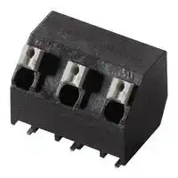
WIRE-TO-BOARD TERMINAL BLOCKS
⚠️ Reference pricing provided. In case of supply shortages, we will connect you with our trusted procurement partners to ensure your project's continuity.
- Manufacturer: WEIDMULLER / PARTNER STOCK
- Product type: Wire-To-Board Terminal Blocks
- SVHC: To Be Advised
| Delivery and price | |
|---|---|
| Units per pack | 450 |
| Price | 0.766 € |
| Current stock | 100+ |
| Lead time | 30 days |
Datasheet

## **Data sheet** ~~Le~~ **OMNIMATE Signal - series LSF LSF-SMD 7.50/04/135 SN BK RL**

## ~~Weidmiiller =~~

**Weidmüller Interface GmbH & Co. KG** Klingenbergstraße 16 D-32758 Detmold Germany Fon: +49 5231 14-0 Fax: +49 5231 14-292083 www.weidmueller.com

## **The innovative quick connector - simple, safe and economical:**

PCB terminals with spring connection and direct PUSH IN technology. A milestone in connection technology. Amazingly simple and simply amazing in practice:

- Connect and easily detach solid wires or wires with wire-end ferrules without using tools

- Processed automatically in the reflow or vapour phase

- Potentials and clamping points marked clearly by coloured push buttons

World-class design-in and processing phases, and suitable for a vast range of applications.

## **PCB terminal for fully automatic assembly using reflow soldering (SMD), with PUSH IN wire connections. Conductor insertion and slider operation from the same direction (TOP).**

- **Solid & flexible conductors with wire-end ferrules need only to be inserted and they are ready.**

- **When connecting stranded wires without wireend ferrules the actuating element is used to open the terminal point**

- **Intuitive handling – since the wire-entry area and handling area are clearly separated.**

## **General ordering data**

|Type|LSF-SMD 7.50/04/135 SN BK RL|
|---|---|
|Order No.|1473910000|
|Version|PCB terminal, 7.50 mm, No. of poles: 4, 135°,|
||Black, PUSH IN, Clamping range, max. : 1.5 mm²,|
||Tape|
|GTIN(EAN)|4050118280944|
|Qty.|210pc(s).|
|Product data|IEC: 800 V / 12 A / 0.2 - 1.5 mm²|
||UL: 300 V/12 A/AWG 24 - AWG 16|
|Packaging|Tape|


- **Packaged in tape-on-reel**

- **Conductor outlet direction 135°**

Creation date July 30, 2018 12:47:50 PM CEST

Catalogue status 13.07.2018 / We reserve the right to make technical changes.

1

**Data sheet** — **OMNIMATE Signal - series LSF LSF-SMD 7.50/04/135 SN BK RL**

## **Technical data** ~~Ld~~

**Weidmüller Interface GmbH & Co. KG** Klingenbergstraße 16 D-32758 Detmold Germany Fon: +49 5231 14-0 Fax: +49 5231 14-292083 www.weidmueller.com ~~a~~

## **Dimensions and weights**

Net weight 5.628 g

## **System parameters**

|Product family|OMNIMATE Signal - series|Wire connection method||
|---|---|---|---|
||LSF||PUSH IN|
|Mountingonto the PCB|SMD solder connection|Conductor outlet direction|135°|
|Pitch in mm(P)|7.5 mm|Pitch in inches(P)|0.295 inch|
|No. ofpoles|4|Fitted bycustomer|No|
|Coplanarity:|100μm|Number of solderpinsperpole|2|
|Strippinglength|8 mm|L1 in mm|22.5 mm|
|L1 in inches||Touch-safe protection acc. to DIN VDE||
||0.885 inch|0470|IP 20|
|Touch-safe protection acc. to DIN VDE||Volume resistance||
|57 106|Safe from finger touch||1.60 mΩ|
|**Material data**||||
|Insulatingmaterial|LCP GF|Colour|Black|
|Colour chart(similar)|RAL 9011|Insulatingmaterialgroup|IIIa|
|CTI|≥ 175|Insulation resistance|≥ 108Ω|
|Moisture Level(MSL)|1|UL 94 flammabilityrating|V-0|
|Contact material|Copper alloy|Layer structure of solder connection|4-6µm Sn matt|
|Storage temperature,min.|-25 °C|Storage temperature,max.|55 °C|
|Max. relative humidityduringstorage|80 %|Operatingtemperature,min.|-50 °C|
|Operatingtemperature,max.|120 °C|Temperature range,installation,min.|-30 °C|


|Insulatingmaterial|LCP GF|
|---|---|
|Colour chart(similar)|RAL 9011|
|CTI|≥ 175|
|Moisture Level(MSL)|1|
|Contact material|Copper alloy|
|Storage temperature,min.|-25 °C|
|Max. relative humidityduringstorage|80 %|
|Operatingtemperature,max.|120 °C|
|Temperature range, installation, max.|120 °C|


## **Conductors suitable for connection**

|Clampingrange,min.|0.13 mm²|Clampingrange,max.|1.5 mm²|
|---|---|---|---|
|Wire connection cross section AWG,||Wire connection cross section AWG,||
|min.|AWG 24|max.|AWG 16|
|Solid,min. H05(07)V-U|0.2 mm²|Solid,max. H05(07)V-U|1.5 mm²|
|Flexible,min. H05(07)V-K|0.2 mm²|Flexible,max. H05(07)V-K|1.5 mm²|
|w. plastic collar ferrule, DIN 46228 pt 4,||w. plastic collar ferrule, DIN 46228 pt 4,||
|min.|0.25 mm²|max.|0.75 mm²|
|w. wire end ferrule, DIN 46228 pt 1, min||w. wire end ferrule, DIN 46228 pt 1,||
||0.25 mm²|max.|1.5 mm²|
|**Rated data acc. to IEC**||||
|tested acc. to standard||Rated current, min. no. of poles||
||IEC 60664-1,IEC 61984|(Tu=20°C)|12 A|
|Rated current, max. no. of poles||Rated current, min. no. of poles||
|(Tu=20°C)|12 A|(Tu=40°C)|12 A|
|Rated current, max. no. of poles||Rated voltage for surge voltage class /||
|(Tu=40°C)|12 A|pollution degree II/2|800 V|
|Rated voltage for surge voltage class /||Rated voltage for surge voltage class /||
|pollution degree III/2|630 V|pollution degree III/3|500 V|
|Rated impulse voltage for surge voltage||Rated impulse voltage for surge voltage||
|class/ pollution degree II/2|6 kV|class/ pollution degree III/2|6 kV|
|Rated impulse voltage for surge voltage||Short-time withstand current resistance||
|class/ contamination degree III/3|6 kV||3 x 1s with 80 A|


Creation date July 30, 2018 12:47:50 PM CEST

Catalogue status 13.07.2018 / We reserve the right to make technical changes.

2

**Data sheet**

## **OMNIMATE Signal - series LSF LSF-SMD 7.50/04/135 SN BK RL**

## **Technical data** ~~ass~~

**Weidmüller Interface GmbH & Co. KG** Klingenbergstraße 16 D-32758 Detmold Germany Fon: +49 5231 14-0 Fax: +49 5231 14-292083 www.weidmueller.com ~~a~~

## **Rated data acc. to CSA**

|**Rated data acc. to CSA**||||
|---|---|---|---|
|Institute (CSA)|Co|Certificate No. (CSA)|200039-1664286|
|Rated voltage(UsegroupB)|300 V|Rated voltage(usegroupD)|300 V|
|Rated current(usegroupB)|10 A|Rated current(usegroupD)|10 A|
|Wire cross-section,AWG,min.|AWG 24|Wire cross-section,AWG,max.|AWG 16|
|Reference to approval values|Specifications are|||
||maximum values, details -|||
||see approval certificate.|||
|**Rated data acc. to UL 1059**||||
|Institute (cURus)|cWAkus|Certificate No. (cURus)|E60693|
|Rated voltage(usegroupB)|300 V|Rated voltage(usegroupD)|300 V|
|Rated current(usegroupB)|12 A|Rated current(usegroupD)|10 A|
|Wire cross-section,AWG,min.|AWG 24|Wire cross-section,AWG,max.|AWG 16|
|Reference to approval values|Specifications are|||
||maximum values, details -|||
||see approval certificate.|||
|**Classifications**||||
|ETIM 3.0|EC001284|ETIM 4.0|EC002643|
|ETIM 5.0|EC002643|ETIM 6.0|EC002643|
|eClass 6.2|27-26-11-01|eClass 7.1|27-44-04-01|
|eClass 8.1|27-44-04-01|eClass 9.0|27-44-04-01|
|eClass 9.1|27-44-04-01|||
|**Notes**||||
|Notes|• Additional push button colours on request|||
||• Operating force of slider max. 40 N|||
||• Rated current related to rated cross-section & min. No. of poles.|||
||• Wire end ferrule with plastic collar to DIN 46228/4|||
||• Wire end ferrule without plastic collar to DIN 46228/1|||
||• P on drawing = pitch|||


||• Rated data refer only to the component itself. Clearance and creepage distances to other components are to|
|---|---|
||be designed in accordance with the relevant application standards.|
||• Crimping shape "A" for wire end ferrules with PZ 6/5 crimping tool are recommended for the largest cable|
||sizes.|
|IPC conformity|Conformity: The products are developed, manufactured and delivered according international recognized|
||standards and norms and comply with the assured properties in the data sheet resp. fulfill decorative properties|
||in accordance with IPC-A-610 "Class 2". Further claims on the products can be evaluated on request.|


Creation date July 30, 2018 12:47:50 PM CEST

Catalogue status 13.07.2018 / We reserve the right to make technical changes.

3

**Data sheet**

## **OMNIMATE Signal - series LSF LSF-SMD 7.50/04/135 SN BK RL**

## **Technical data** ~~ass~~

**Weidmüller Interface GmbH & Co. KG** Klingenbergstraße 16 D-32758 Detmold Germany Fon: +49 5231 14-0 Fax: +49 5231 14-292083 www.weidmueller.com ~~So~~

## **Approvals**

|**Approvals**||
|---|---|
|Approvals|@SALuslill|
|ROHS|Conform|
|**Downloads**||
|Approval/Certificate/Document of||
|Conformity|Declaration of the Manufacturer|
|Brochure/Catalogue|FL DRIVES EN|
||PI OMNIMATE LSF SMD EN|
||FL ANALO.SIGN.CONV. EN|
||MB DEVICE MANUF. EN|
||FL DRIVES DE|
||FL BUILDING SAFETY EN|
||FL APPL LED LIGHTING EN|
||FL INDUSTR.CONTROLS EN|
||FL MACHINE SAFETY EN|
||FL HEATING ELECTR EN|
||FL APPL_INVERTER EN|
||FL_BASE_STATION_EN|
||FL ELEVATOR EN|
||FL POWER SUPPLY EN|
||FL 72H SAMPLE SER EN|
||PO OMNIMATE EN|
|EngineeringData|EPLAN, WSCAD|
|EngineeringData|STEP|
|SMT white paper|Download Whitepaper|


Creation date July 30, 2018 12:47:50 PM CEST

Catalogue status 13.07.2018 / We reserve the right to make technical changes.

4

**Data sheet**

## **OMNIMATE Signal - series LSF LSF-SMD 7.50/04/135 SN BK RL**

## **Drawings**

**Weidmüller Interface GmbH & Co. KG** Klingenbergstraße 16 D-32758 Detmold Germany Fon: +49 5231 14-0 Fax: +49 5231 14-292083 www.weidmueller.com

## **Dimensional drawing**

**Graph**

Creation date July 30, 2018 12:47:50 PM CEST

Catalogue status 13.07.2018 / We reserve the right to make technical changes.

5

**Data sheet**

## **OMNIMATE Signal - series LSF LSF-SMD 7.50/04/135 SN BK RL**

**Drawings**

**Weidmüller Interface GmbH & Co. KG** Klingenbergstraße 16 D-32758 Detmold Germany Fon: +49 5231 14-0 Fax: +49 5231 14-292083 www.weidmueller.com

## **Dimensional drawing**

## **Dimensional drawing**

Creation date July 30, 2018 12:47:51 PM CEST

Catalogue status 13.07.2018 / We reserve the right to make technical changes.

6

**Lötp**

##

**Weidmüller Interface GmbH & Co. KG** Klingenbergstraße 16 D-32758 Detmold Germany Fon: +49 5231 14-0 Fax: +49 5231 14-292083 www.weidmueller.com

## **Einzelwelle:**

**==> picture [433 x 447] intentionally omitted <==**

**----- Start of picture text -----**<br>
Kontaktzeit ca. 3 sec.<br>260 255 °C ¢ — ~, NS, 260 °C<br>240 250 °C H NSoNNSrv N AS<br>220 \‘\ ‘ASN.<br>200 \\\N.X.\<br>\ [NS.][NS,]<br>180 1\ NS,aS<br>\ *<br>160 en,\\ ca. 150 °C ‘s ‘~<br>140 oo * \ a<br>12010080 Vorwärmung ? ? 7 7aa ?aPa”&a“iS&S .onweer"<cc“7TO°°reaps<1i a -oN\\‘‘‘ ‘‘\N,ave“-*s|°* Abkühlrate < 6 °K/s . .|:>°.= D7;.Bo,sek ; -mek7 7" =<br>, f. Dosa ,<br>60 wo { wee .<br>4020 ZL|Keer¢?; ,,<ifen-"y = Aufheizrate < 3 °K/s NS,NS,N,S,.,. ~ “~~ —— Typisches VerfahrenVerfahrensgrenzenTemperatur auf der Leiterplatte<br>0<br>0  20  40  60  80  100  120  140  160  180  200  220  240<br>Zeit [s]<br>Doppelwelle:<br> Gesamtkontaktzeit max. 10 sec.<br>260 255 °C — 260 °C<br>I? 250 °C<br>240<br>220<br>200<br>180<br>t)<br>\<br>160 pecorstn \\<br>1401201008060 Vorwärmung -*o”ooy¢¢777“<aKaa 7ao*SeefeePedo&&PeaofS.veof*SSa// <.<4<AS<sen<4;;<‘.a/ ca. 150 °C aemoN‘ONSaS‘,‘:‘“\;;,S,",>, Abkühlrate < 6 °K/s >Ss,.‘.. — <:S,ans:an:;.; Typisches Verfahren >™::.a:°-:./;;~a“ :<br>40 Pred-_—-" =<ae Verfahrensgrenzen<br>20 Aufheizrate < 3 °K/s Temperatur auf der Leiterplatte<br>0<br>0  20  40  60  80  100  120  140  160  180  200  220  240<br>Zeit [s]<br>Temperatur [°C]<br>Temperatur [°C]<br>**----- End of picture text -----**<br>


##

Bedrahtete Anschlusselemente sind in Anlehnung an die Norm DIN EN 61760-1 zu verarbeiten. Anbei zwei Empfehlungen für praxisbezoge Wellenlötprofile, mit denen Leiterplattenanschlussklemmen und Steckverbinder von Weidmüller qualifiziert sind.

- Stärke der Leiterplatte

- Cu-Anteile in den Lagen

- Ein-/Beidseitige Bestückung

- Produktspektrum

- Aufheiz- und Abkühlrate

Die Einzel- und Doppelwelle zeigt jeweils den empfohlenen Verarbeitungsbereich inkl. der maximalen  Löttemperatur von 260°C. In der Praxis liegt die maximale Löttemperatur sehr häufig weit unter dem o.g. Maximalprofil.

Technische Änderungen vorbehalten

##

**Weidmüller Interface GmbH & Co. KG** Klingenbergstraße 16 D-32758 Detmold Germany Fon: +49 5231 14-0 Fax: +49 5231 14-292083 www.weidmueller.com

**==> picture [510 x 255] intentionally omitted <==**

**----- Start of picture text -----**<br>
300<br>oe 254 °C<br>250 245 °C - aa<br>235 °C oo x<br>Melting point lead-free solder paste<br>217 o awe Ss<br>190 °C approx.  XN XN<br>200 vane yr 60 s > 217 °C XN<br>XN \<br>180 °C Pad , N \<br>----7 _-7 \ \ \ \<br>150 77 \ N\<br>preheating , o7 a Cooling rate: < 6 °K/s . ‘ \<br>100 o \<br>of \<br>o a \<br>aa Heating rate: < 3 °K/s \<br>a \<br>50 &<br>a<br>& — Continuous line: Typical process<br>a 7 -_ — Dotted line:   Process limits<br>0<br>0  50  100  150  200  250  300  350<br>Temperature [°C]<br>**----- End of picture text -----**<br>


**Time [sec]**

##

But there are more than one correct answer: The diagram of temperature-on-time is related to processing features of solder paste and to maximum load of components.

We have to consider the following parameters:

- Time for pre heating

- Maximum temperature

- Time above melting point

- Time for cooling

- Maximum heating rate

- Maximum cooling rate

prepared smoothly for the solder phase. Heating rate is typically  ≤ +3K/s. In parallel the solder paste is ‚activated’. The time above melting point of 217°C the paste gets liquid and components and boards begin to connect. The maximum temperature of 245°C to 254°C should stay between 10 and 40 seconds. In the cooling phase at ≥ -6K/s solder is cured. Board and components cool down while avoiding cold cracks.

We reserve the right to make technical changes.
Updated at June 9, 2026
About Novapart
Novapart is a B2B electronic component broker specialising in stock shortages and cost reduction. We source hard-to-find parts and identify compliant alternatives across a catalogue of 410,000+ components from 500+ manufacturers.
Learn more →Stock Shortage Specialist
When a component is unavailable, discontinued or has an unacceptable lead time, we tap into our network of vetted European and Asian distributors to source what you need — without compromising on quality or traceability.
Request a quote →Compliant Alternatives
We identify pin-to-pin, electrically equivalent substitutes that meet the same certifications (RoHS, AEC-Q100, REACH) as your original specification — validated against datasheets, not just part numbers. Often at a lower cost.
BOM Analysis service →