
Image not available
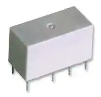
Illustrative purposes only

1462035-3
Signal Relay, 5 VDC, DPDT, 2 A, FT2, Through Hole, Non Latching
⚠️ Reference pricing provided. In case of supply shortages, we will connect you with our trusted procurement partners to ensure your project's continuity.
- Manufacturer: Axicom
- Product type: Signal Relays
- Coil Type: Non Latching
- Coil Voltage: 5VDC
- Product Range: FT2
- Relay Mounting: Through Hole
- Coil Resistance: 83ohm
- Contact Current: 2A
- Relay Terminals: Solder
- Contact Material: Palladium Ruthenium
- Contact Voltage VAC: 250V
- Contact Voltage VDC: 220V
- Contact Configuration: DPDT
| Delivery and price | |
|---|---|
| Units per pack | 250 |
| Price | 1.91 € |
| Current stock | 10+ |
| Lead time | 30 days |
Datasheet

Signal Relays

**AXICOM**

## **FT2/FU2 Relay**

- n **Telecom/signal relay (dry circuit, test access, ringing)** n **Slim line 15x7.5mm (.59x.295”)**

- n **Switching current 2A**

- n **2 form C bifurcated contacts (2 CO)**

- n **High sensitive 24V and 48V coil versions**

- n **Meets Telcordia GR 1089, FCC Part 68 and ITU-T K20, ≥ 2500V between coil and contacts**

## Typical applications

Communications equipment, linecard application – analog, ISDN, xDSL, PABX, voice over IP, office and business equipment, measurement and control equipment, consumer electronics, set top boxes, HiFi, medical equipment

**==> picture [224 x 455] intentionally omitted <==**

**----- Start of picture text -----**<br>
||||||
|---|---|---|---|---|
|Approvals|
|UL 508 File No. E 111441|
|Technical data of approved types on request|
|Contact Data|
|Contact arrangement|2 Form C (CO)|
|Max. switching voltage|220VDC, 250VAC|
|Rated current|2A|
|Limiting continuous current|2A|
|Switching power|60W, 62.5VA|
|Contact material|PdRu, Au covered|
|Contact style|twin contacts|
|Min. recommended contact load|100µV/1µA|
|Initial contact resistance|<50mΩ|
|Thermoelectric potential|<10µV|
|Operate time|typ. 3ms, max. 5ms|
|Release time|
|without diode in parallel|typ. 2ms, max. 5ms|
|with diode in parallel|typ. 4ms, max. 5ms|
|Bounce time max.|typ. 1ms, max. 5ms|
|Electrical endurance|
|at contact application 0|
|(≤ 30mV/≤10mA)|min. 2.5x10|[6]|operations|
|cable load open end|min. 2.0x10|[6]|operations|
|resistive, 24V / 1.25A - 30W|min. 1x10|[5]|operations|
|resistive, 30VDC / 2A - 60W|min. 1x10|[5]|operations|
|resistive, 125VDC / 0.24A - 30W|min. 1x10|[5]|operations|
|Contact ratings, UL contact rating|220VDC, 0.24A, 60W|
|125VDC, 0.24A, 30W|
|250VAC, 0.25A, 62.5VA|
|125VAC, 0.5A, 62.5VA|
|30VDC, 2A, 60W|
|Mechanical endurance|100x10|[6]|operations|
|Max. DC load breaking capacity|
|ee|ll|
|100 SSSIaN||
|Po|NTT|
|a|
|so|LF|TTT|XN|ETT|
|yo|ETN|TTT|
|wo|eT|ETT|
|29|| recommended|Baill|
|10|application range|iil|

**----- End of picture text -----**<br>


## Z

**==> picture [253 x 224] intentionally omitted <==**

**----- Start of picture text -----**<br>
||||||||
|---|---|---|---|---|---|---|
|Coil Data|
|Magnetic system|monostable, non polarized|
|Coil voltage range|3 to 48VDC|
|Max. coil temperature|150°C|
|Thermal resistance|<125K/W|
|Coil versions, monostable|
|Coil|Rated|Operate|Limiting|Release|Coil|Rated coil|
|code|voltage|voltage|voltage|voltage|resistance|power|
|VDC|VDCmin.|VDCmax.|VDCmin.|Ω±10%|mW|
|Standard version, monostable|
|21|3|2.25|6.80|0.30|45|200|
|29|4|3.00|9.00|0.40|80|200|
|22|4.5|3.38|10.10|0.45|101|200|
|23|5|3.75|11.20|0.50|125|200|
|24|6|4.50|13.50|0.60|180|200|
|25|9|6.75|20.30|0.90|405|200|
|26|12|9.00|27.00|1.20|720|200|
|27|24|18.00|47.50|2.40|2400|240|
|28|48|36.00|95.00|4.80|9600|240|
|High dielectric version, monostable|
|91|3|2.25|6.80|0.30|45|200|
|93|5|3.75|11.20|0.50|125|200|
|96|12|9.00|27.00|1.20|720|200|
|97|24|18.00|47.50|2.40|2400|240|

**----- End of picture text -----**<br>


All figures are given for coil without pre-energization, at ambient temperature +23°C. Other coil voltages on request.

**==> picture [187 x 147] intentionally omitted <==**

**----- Start of picture text -----**<br>
2.6 200 mW coil<br>2.4 240 mW coil<br>2.2 <= Umax. at 0 A<br>2 Umax. at 2 x 1 A<br>1.8 Umax. at 2 x 2 A<br>—<S> x<br>1.6<br>1.4<br>1.2<br>1 Unom. nominal coil voltage 7<br>0.8<br>0.6 Uop. min.<br>0.4 Urel. min.<br>0.2 a<br>0 o T<br>-60 -50 -40 -30 -20 -10 0 10 20 30 40 50 60 70 80 90 10 11 12 13 14<br>Ambient Temperature [°C] 0 0 0 0 0<br>]nom<br>Coil Voltage [U/U<br>**----- End of picture text -----**<br>


**==> picture [34 x 6] intentionally omitted <==**

**----- Start of picture text -----**<br>
DC current [A]<br>**----- End of picture text -----**<br>


Datasheets and product specification according to IEC 61810-1 and to be used only together with the ‘Definitions’ section.

1

Datasheets, product data, ‘Definitions’ section, application notes and all specifications are subject to change.

01-2013, Rev. 0113 www.te.com © 2013 Tyco Electronics Corporation, a TE Connectivity Ltd. company

Datasheets and product data is subject to the terms of the disclaimer and all chapters of the ‘Definitions’ section, available at http://relays.te.com/definitions

Signal Relays

**AXICOM**

## ~~**F**~~ **T2/FU2 Relay** (Continued)

**==> picture [511 x 170] intentionally omitted <==**

**----- Start of picture text -----**<br>
|||||||||||
|---|---|---|---|---|---|---|---|---|---|
|Coil Data|(continued)|Insulation|standard|high dielectric|
|Initial dielectric strength|
|Coil versions, monostable|between open contacts|1000Vrms|1500Vrms|
|Coil|Rated|Operate|Limiting|Release|Coil|Rated coil|between contact and coil|1500Vrms|4000Vrms|
|code|voltage|voltage|voltage|voltage|resistance|power|between adjacent contacts|1500Vrms|1800Vrms|
|VDC|VDCmin.|VDCmax.|VDCmin.|Ω±10%|mW|Initial surge withstand voltage|
|High dielectric Australia version, monostable|between open contacts|1500V|2500V|
|71|3|2.25|5.50|0.30|30|300|between contact and coil|2500V|6000V|
|73|5|3.75|9.20|0.50|83|300|between adjacent contacts|1500V|2500V|
|76|12|9.00|22.10|1.20|480|300|Initial insulation resistance|
|All figures are given for coil without pre-energization, at ambient temperature +23°C.|between insulated elements|>10|[9]|Ω|>10|[9]|Ω|
|Other coil voltages on request.|Capacitance|
|between open contacts|max. 4pF|
|2.6|300 mW coil|between contact and coil|max. 1pF|
|2.4|between adjacent contacts|max. 1pF|
|Cross talk at 100MHz/900MHz|-30.6dB/-13.7dB|
|2.2|Umax. at 0 Amax. at 0 A at 0 A|Insertion loss at 100MHz/900MHz|-0.02dB/-0.50dB|
|2.0|UUmax.max. at 2 x 1 A at 2 x 2 Amax. at 2 x 1 A at 2 x 2 Amax.max. at 2 x 1 A at 2 x 2 A at 2 x 2 A at 2 x 1 A at 2 x 2 A|Voltage standing wave ratio (VSWR)|
|1.8|at 100MHz/900MHz|1.02 / 1.27|

**----- End of picture text -----**<br>


**==> picture [198 x 162] intentionally omitted <==**

**----- Start of picture text -----**<br>
2.6 300 mW coil<br>2.4<br>2.2 Umax. at 0 Amax. at 0 A at 0 A<br>2.0<br>Umax.max. at 2 x 1 A at 2 x 2 AUUmax.max. at 2 x 1 A at 2 x 2 Amax. at 2 x 1 A at 2 x 2 Amax.max. at 2 x 1 A at 2 x 2 A at 2 x 2 A at 2 x 1 A at 2 x 2 A<br>1.8<br>1.6<br>1.4<br>1.2<br>1.0 Unom. nominal coil voltage<br>0.8<br>0.6<br>Uop. min.<br>0.4 Urel. min.<br>0.2<br>0.0<br>-60 -50 -40 -30 -20 -10 0 10 20 30 40 50 60 70 80 90 100 110 120 130 140<br>Ambient Temperature [°C]<br>]nom<br>Coil Voltage [U/U<br>**----- End of picture text -----**<br>


**==> picture [253 x 190] intentionally omitted <==**

**----- Start of picture text -----**<br>
|||
|---|---|
|Other Data|
|Material compliance: EU RoHS/ELV, China RoHS, REACH, Halogen content|
|refer to the Product Compliance Support Center at|
|www.te.com/customersupport/rohssupportcenter|
|Ambient temperature|-55°C to +85°C|
|Thermal resistance|<125K/W|
|Category of environmental protection|
|IEC 61810|RT III - immersion cleanable|
|Degree of protection, IEC 60529|IP 67, immersion cleanable|
|Vibration resistance (functional)|10g, 10 to 500Hz|
|Shock resistance (functional), half sinus 11ms|15g|
|Shock resistance (destructive), half sinus 0.5ms|500g|
|Weight|max. 3g|
|Resistance to soldering heat  THT|
|IEC 60068-2-20|265°C/10s|
|Moisture sensitive level, JEDEC J-Std-020D|MSL3|
|Ultrasonic cleaning|not recommended|
|Packaging/unit|
|THT version|tube/50 pcs., box/2000 pcs.|
|SMT short terminals|reel/500 pcs.,box/2500 pcs.|
|SMT long terminals|reel/400 pcs.,box/2000 pcs.|

**----- End of picture text -----**<br>


Umax upper limit of the operative range of the coil voltage (limiting voltage) when coils are continuously energized

Uop min lower limit of the operative range of the coil voltage (reliable operate voltage) Urel min lower limit of the operative range of the coil voltage (reliable release voltage)

## **Terminal assignment**

TOP view on component side of PCB

## **PCB layout**

TOP view on component side of PCB

THT version

SMT, long terminals

SMT, short terminals

2

Datasheets and product specification according to IEC 61810-1 and to be used only together with the ‘Definitions’ section.

Datasheets and product data is subject to the Datasheets, product data, ‘Definitions’ secterms of the disclaimer and all chapters of tion, application notes and all specifications the ‘Definitions’ section, available at are subject to change. http://relays.te.com/definitions

01-2013, Rev. 0113 www.te.com © 2013 Tyco Electronics Corporation, a TE Connectivity Ltd. company

Signal Relays

**AXICOM**

## **FT2/FU2 Relay** (Continued)

**==> picture [44 x 6] intentionally omitted <==**

**----- Start of picture text -----**<br>
Dimensions<br>**----- End of picture text -----**<br>


**==> picture [120 x 100] intentionally omitted <==**

**----- Start of picture text -----**<br>
THT version<br>15.0±0.05 7.5±0.05<br>t<br>0.5<br>5.08<br>.35±0.03<br>0 9.6±0.03<br>3.3±0.03<br>**----- End of picture text -----**<br>


**==> picture [135 x 101] intentionally omitted <==**

**----- Start of picture text -----**<br>
SMT, long terminals<br>15.0±0.05 7.5±0.05<br>0.5 _ 5.08<br>9.2±0.2<br>coplanarity ≤0.1mm u —be-<br>10.0±0.15<br>**----- End of picture text -----**<br>


**==> picture [134 x 103] intentionally omitted <==**

**----- Start of picture text -----**<br>
SMT, short terminals<br>15.0±0.05 7.6±0.05<br>0.5 - 5.08<br>7.5±0.2<br>coplanarity ≤0.1mm<br>10.0±0.15<br>**----- End of picture text -----**<br>


## **Processing**

**==> picture [241 x 145] intentionally omitted <==**

**----- Start of picture text -----**<br>
300 Recommended soldering conditionsVapour phase soldering 20 to 40s full line: typical<br>240°C dotted line: process limits<br>200 rite,<br>180°C<br>150 130°C forced cooling oa<br>external preheating<br>100 100°C ¥<br>50 Vapour phase soldering temperature/time profile<br>(lead and housing peak temp.)<br>0 () 50 100 150 200 Time [s] 250<br>Temperature [°C]<br>**----- End of picture text -----**<br>


##

**==> picture [200 x 114] intentionally omitted <==**

**----- Start of picture text -----**<br>
Infrared soldering<br>temperature/time profile<br>(lead and housing peak temp.)<br>180<br>150<br>60s<br>max. 3 °C/s<br>25<br>Time [s]<br>Temperature [°C]<br>**----- End of picture text -----**<br>


3

Datasheets and product specification according to IEC 61810-1 and to be used only together with the ‘Definitions’ section.

Datasheets, product data, ‘Definitions’ section, application notes and all specifications are subject to change.

01-2013, Rev. 0113 www.te.com © 2013 Tyco Electronics Corporation, a TE Connectivity Ltd. company

Datasheets and product data is subject to the terms of the disclaimer and all chapters of the ‘Definitions’ section, available at http://relays.te.com/definitions

Signal Relays

**AXICOM**

## **FT2/FU2 Relay** (Continued)

**==> picture [31 x 8] intentionally omitted <==**

**----- Start of picture text -----**<br>
Packing<br>**----- End of picture text -----**<br>


**==> picture [454 x 429] intentionally omitted <==**

**----- Start of picture text -----**<br>
Fe a 4±0.1 en B , 2±0.1 oe 1.5 0.1 — roztec transportnichdistance of transpor4x10=40±0.2mm4x11=44±0.2mm4x12=48±0.2mm B-B { i A-A Z ! NEW<br>B<br>r- @ C010 ff D OO 00 1 H —— ! ! i I if<br>LJ L l wi LL A iAr—— i rt 4±0.2 | i<br>o) 9 i _= i!! ! fae ; SS a<br>A<br>9.9±0.2<br>1 f a | | a | 1. 5 0.1 1.2 [+0]  0 1.2 ! [+0.2]  0 — ———— | -_L 11.9±0.2 |— _— 12.1±0.2 —- _<br>B 16±0.15<br>6 B B A A<br>| Xe, oe 2 p 3<br>2 440.1 |240.1 °° 4 max . Ke y<br>S Eee Fy = b as ) T e<br>Nj p d f fy FI N<br>A 4 H Y i )<br>e lo & Pacrdm S | i<br>) | I +H t+} + Y y 4) y fo)<br>os TO Ie A lL o wo} lyy t S2o ) YY f ytHf YH =<br>a+ ___ : it | Hf e s  oe oe teporerrrr zhorzezIZIEA peecceceserststeeets<br>Ley LL 1 1/ 8 | 10+0.2 _| L_12'+0.2<br>e ae [=] [g] Tape and reel for SMT  |<br>version with long terminals<br>B<br>4±0.1 B 2±0.1 1.5 0.1 roztec trandistance of4x10=40±04x11=44±04x12=48±0 mm B-B A-A NEW<br>fo po y al Fi<br>Hoo 610 06 6 ¢ ; - ! | Ir} |<br>| Le a l | Ul ! i __ , ! (|{| i| | ||[<br>A . 4±0.2 t } |<br>1 idl ranSZ Hiab ‘o) [ i ri — i 1} ZZZZ> / ( ZA| ZZ [27777] Uj<br>; ee an) een<br>A Frit 8±0.2 ZZ<br>1 se os 1.2 ' [+0.2]  0 -——SS i _~ 9±0.2 7_ _ 9.1±0.2 ~ _<br>1.5 0.1<br>B 12±0.15<br>ey B B° - B y max. 3°<br>No 440.1] 240.1 eo Ay n ico 7)<br>a 8 gal s |<br>ROa Ole 4 pq ae tS 9i HYi y4m s :<br>yg iS a ) -——" 5 HY ,<br>LbL bJtJ_.Whld SLA4 i. Swo+)| ) f4 a 3 I i f44 H4HYyfWY 4yy S x=- t<br>JA | ¢ iS =| a -— — "__* yUrabe4 ¥WheeerrareadY<br>bj gb ( oS 720.2|<br>Tape and reel for SMT<br>gQin 8.6 +0.2 version with long terminals<br>max. 3°<br>max. 3°<br>max. 3°<br>max. R0.3 max. 3°<br>max. 3°<br>max. R0.3<br>max. 3°<br>max. R0.3<br>max. R0.3<br>max. 3°<br>max. 3°<br>1.75±0.1 0.6<br>(3.6)<br>1.9±0.2 4.5±0.2<br>11.5±0.1 2.2±0.2 +0.310.9 0<br>24±0.3 15.4±0.2<br>15.4±0.2<br>1 3±0 2 1.3±0.2<br>1.9±0.2<br>(3.6)<br>1.75±0.1 0.6<br>(3.6) 1.9±0.2 4.5±0.2<br>11.5±0.1 2.2±0.2 +0.310.9 0<br>24±0.3 15.4±0.2<br>1.3±0.2<br>(3.6) 1.9±0.2<br>**----- End of picture text -----**<br>


**==> picture [55 x 6] intentionally omitted <==**

**----- Start of picture text -----**<br>
Reel dimensions<br>**----- End of picture text -----**<br>


**==> picture [112 x 41] intentionally omitted <==**

**----- Start of picture text -----**<br>
4<br>01-2013, Rev. 0113<br>www.te.com<br>© 2013 Tyco Electronics Corporation,<br>a TE Connectivity Ltd. company<br>**----- End of picture text -----**<br>


Datasheets and product specification according to IEC 61810-1 and to be used only together with the ‘Definitions’ section.

Datasheets and product data is subject to the Datasheets, product data, ‘Definitions’ secterms of the disclaimer and all chapters of tion, application notes and all specifications the ‘Definitions’ section, available at are subject to change. http://relays.te.com/definitions

**AXICOM**

## Signal Relays

## **FT2/FU2 Relay** (Continued)

## **Product code structure**

Typical product code **D34 02**

**==> picture [277 x 127] intentionally omitted <==**

**----- Start of picture text -----**<br>
|||
|---|---|
|Type|
|D34|Signal Relays FT2 (THT)|
|D35|Signal Relays FU2 (SMT)|
|2 form C, 2 CO|
|Coil|
|Coil code: please refer to coil versions table|
|Performance and coil type|
|2x|Standard version, monostable|
|9x|High dielectric version, monostable|
|7x|High dielectric, Australia version, monostable (SMT version only)|
|Terminals|
|Blank|,(L) THT, Standard version|
|N|SMT, short pins|
|W|SMT, long pins|

**----- End of picture text -----**<br>


**==> picture [511 x 144] intentionally omitted <==**

**----- Start of picture text -----**<br>
||||||||
|---|---|---|---|---|---|---|
|Product code|Arrangement|Perf. type|Coil type|Coil|Terminals|Part number|
|D3421|2 form C (2 CO)|Standard|Monostable|3VDC|THT|1462035-9|
|D3423|5VDC|1-1462035-1|
|D3426|12VDC|1-1462035-4|
|D3427|24VDC|1-1462035-7|
|D3523N|2 form C (2 CO)|Standard|Monostable|5VDC|SMT short|2-1462036-1|
|D3527N|24VDC|2-1462036-9|
|D3528N|48VDC|9-1462036-3|
|D3521W|2 form C (2 CO)|Standard|Monostable|3VDC|SMT long|1-1462036-8|
|D3522W|4.5VDC|2-1462036-0|
|D3523W|5VDC|2-1462036-2|
|D3526W|12VDC|2-1462036-8|
|D3527W|24VDC|9-1462036-1|
|D3491L|2 form C (2 CO)|High dielectric|Monostable|3VDC|THT|2-1462035-7|
|D3493L|5VDC|2-1462035-8|
|D3496|12VDC|2-1462035-4|
|D3497|24VDC|2-1462035-5|

**----- End of picture text -----**<br>


This list represents the most common types and does not show all variants covered by this data sheet. Other types on request

5

Datasheets and product specification according to IEC 61810-1 and to be used only together with the ‘Definitions’ section.

Datasheets, product data, ‘Definitions’ section, application notes and all specifications are subject to change.

01-2013, Rev. 0113 www.te.com © 2013 Tyco Electronics Corporation, a TE Connectivity Ltd. company

Datasheets and product data is subject to the terms of the disclaimer and all chapters of the ‘Definitions’ section, available at http://relays.te.com/definitions
Updated at February 9, 2023
About Novapart
Novapart is a B2B electronic component broker specialising in stock shortages and cost reduction. We source hard-to-find parts and identify compliant alternatives across a catalogue of 410,000+ components from 500+ manufacturers.
Learn more →Stock Shortage Specialist
When a component is unavailable, discontinued or has an unacceptable lead time, we tap into our network of vetted European and Asian distributors to source what you need — without compromising on quality or traceability.
Request a quote →Compliant Alternatives
We identify pin-to-pin, electrically equivalent substitutes that meet the same certifications (RoHS, AEC-Q100, REACH) as your original specification — validated against datasheets, not just part numbers. Often at a lower cost.
BOM Analysis service →