
Image not available
Illustrative purposes only

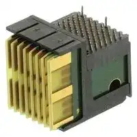
1410189-3
Connector, MULTIGIG RT Series, 8 Contacts, 20.3 mm, Plug, Through Hole, 7 Rows
⚠️ Reference pricing provided. In case of supply shortages, we will connect you with our trusted procurement partners to ensure your project's continuity.
- Manufacturer: TE CONNECTIVITY / PARTNER STOCK
- Product type:
- SVHC: Lead (21-Jan-2025)
- Gender: Plug
- Row Pitch: 1.35mm
- No. of Rows: 7Rows
- Pitch Spacing: 20.3mm
- Product Range: MULTIGIG RT Series
- Contact Plating: Gold Plated Contacts
- No. of Contacts: 8Contacts
- Contact Material: Phosphor Bronze
- Contact Termination Type: Through Hole
| Delivery and price | |
|---|---|
| Units per pack | 90 |
| Price | 47.65 € |
| Current stock | 500+ |
| Lead time | 30 days |
Datasheet

High Speed Backplane Connectors

**5**

## **Table of Contents**

**==> picture [367 x 136] intentionally omitted <==**

**----- Start of picture text -----**<br>
||||
|---|---|---|
|MULTIGIG RT Connector|. . . . . . . . . . . . . . . . . . . . . . . . . . . . . . . . . . . . . . . . . . . . . 137-162|
|Product Line Overview|. . . . . . . . . . . . . . . . . . . . . . . . . . . . . . . . . . . . . . . . . . . . . . . . . . 138|
|Connector Sequencing Chart|. . . . . . . . . . . . . . . . . . . . . . . . . . . . . . . . . . . . . . . . . . . . . 139|
|Mating Sequencing Chart|. . . . . . . . . . . . . . . . . . . . . . . . . . . . . . . . . . . . . . . . . . . . . . . . 140|
|Product Selection Guide|. . . . . . . . . . . . . . . . . . . . . . . . . . . . . . . . . . . . . . . . . . . . . 141-143|
|Customization Options|. . . . . . . . . . . . . . . . . . . . . . . . . . . . . . . . . . . . . . . . . . . . . . 144-146|
|MULTIGIG RT Tier 1 Connector System|. . . . . . . . . . . . . . . . . . . . . . . . . . . . . . . . 147, 148|
|MULTIGIG RT Tier 2 Connector System|. . . . . . . . . . . . . . . . . . . . . . . . . . . . . . . . 149, 150|
|Connector Selection Grid for VITA 41 VXS Compliant Connectors|. . . . . . . . . . . . . 151-153|
|Connector Selection Grid for VITA 46 VPX Compliant Connectors|. . . . . . . . . . . . . 154-157|
|“New”|MULTIGIG RT Stacking Connector|. . . . . . . . . . . . . . . . . . . . . . . . . . . . . . . . . . . 158|
|Power Modules and Guide Hardware Reference|. . . . . . . . . . . . . . . . . . . . . . . . . . 159-162|

**----- End of picture text -----**<br>


VITA, VMEbus, VPX, and VXS are trademarks of VITA.

137 Dimensions are in millimeters Canada: +1 (905) 475-6222 UK: +44 (0) 800-267666 and inches unless otherwise Mexico/C. Am.: +52 (0) 55-1106-0800 France: +33 (0) 1-3420-8686 specified. Latin/S. Am.: +54 (0) 11-4733-2200 Netherlands: +31 (0) 73-6246-999 USA: +1 (800) 522-6752 Germany: +49 (0) 6251-133-1999 China: +86 (0) 400-820-6015

Catalog 1773095 Dimensions are shown for Revised 4-12 reference purposes only. Specifications subject www.te.com to change.

High Speed Backplane Connectors

## **MULTIGIG RT Connector Products**

## **Product Facts**

- I **Customizable impedance matched printed circuit wafer interface**

- I **Available for stacking applications**

- I **Inverse sex backplane connector system with “pinless” interface**

- I **Superior crosstalk performance**

- I **Optimized footprints for signal integrity and ease of board design**

- I **Utilizes a 0.56 [.022] diameter via for backplane connector for lower cost board fabrication**

- I **Three levels of signal contact sequencing**

- I **Available in modular style**

- I **Available for 20.30 [.800] or 25.40 [1.00] card pitch systems**

- I **Durability rated for 200 cycles**

- I **Fully compatible with MP based fiber optic array interconnects**

- I **Complete connector family includes**

- I **Power Modules = > Maximize Amps/inch density, voltages in pairs**

- I **Guidance Modules**

- I **Die cast for strength**

- I **Optional ESD contact** I **Three sequence levels**

The MULTIGIG RT product allows for cost effective line is a backplane interconsequencing and electrical nect family that offers flexicustomization of the conbility and customization. nector. Wafers can be manThis printed circuit based, ufactured specifically for pinless, interconnect family differential or signal ended is comprised of modular performance and the components which can be impedance, propagation used in a variety of combidelay, and crosstalk of the nations. The connectors in connector can be altered this innovatively flexible per customer requirements. platform can be combined This scalable board to to provide the density, data backplane connector family throughput, and signal is a robust, “pinless” design integrity required for appliwhich eliminates the pin cations in today’s computer, field on backplane boards military, medical, or indusand reduces the end user’s trial control industries. The exposure to field failure in use of printed circuit wafers card cage systems. The in this connector system MULTIGIG RT connector

family is designed specifically for 20.30 [.800] or 25.40 [1.00] card pitch systems.

I **MULTIGIG RT 1 connector** — 141 signals/inch, data rates up to 3.125 Gb/s

I **MULTIGIG RT 2 connector** — 113 signals/inch, data rates of 3.125 Gb/s to 6.4 Gb/s and has been demonstrated to support 10 Gb/s

## **www.multigigrt.com**

- I **Press fit or hardware mounted**

- I **Backplane drill pattern enabled keying**

- I **Cable assembly proposals available**

- I **MULTIGIG RT connector products are fully compatible with 2mm HM equipment practices**

## **Applications**

- I **Telecommunications Equipment**

- I **Metro Optical Networking equipment**

- I **SONET switched platforms**

- I **Aggregation switches**

- I **Midrange Servers**

- I **High End Servers**

- I **High speed custom platforms**

- I **Mass data storage**

- I **Rugged, mission-critical applications**

## **Technical Documents**

**Application Specifications** 114-13062 Power Modules 114-13056 Signal Connectors

**Product Specifications** 108-2062 Power Modules 108-2072 Signal Connectors

**Qualification Test Reports** 501-538 Power Connectors 501-544 Signal Connectors

**Engineering Report**

502-1130 Power Connectors Routing Guide RT 2 on te.com

138 Catalog 1773095 Revised 4-12

Dimensions are shown for Dimensions are in millimeters Canada: +1 (905) 475-6222 UK: +44 (0) 800-267666 reference purposes only. and inches unless otherwise Mexico/C. Am.: +52 (0) 55-1106-0800 France: +33 (0) 1-3420-8686 Specifications subject specified. Latin/S. Am.: +54 (0) 11-4733-2200 Netherlands: +31 (0) 73-6246-999 to change. USA: +1 (800) 522-6752 Germany: +49 (0) 6251-133-1999 China: +86 (0) 400-820-6015

www.te.com

High Speed Backplane Connectors

## **MULTIGIG RT Connector Products** (Continued)

## **MULTIGIG RT Connector Sequencing Chart**

##

**==> picture [470 x 232] intentionally omitted <==**

**----- Start of picture text -----**<br>
20.75 mm Key on Guide Pin<br>ESD Contact on<br>18.25 mm<br>Guide Pin<br>11.25 mm Power Level 3<br>9.75 mm Power Level 2<br>Power Level 1<br>8.25 mm<br>5.5 mm Signal Level 3<br>Ground Level<br>4.0 mm Signal Level 2<br>2.5 mm<br>Signal Level 1<br>0 3 6 9 12 15 18 21<br>**----- End of picture text -----**<br>


**5**

139 Dimensions are in millimeters Canada: +1 (905) 475-6222 UK: +44 (0) 800-267666 and inches unless otherwise Mexico/C. Am.: +52 (0) 55-1106-0800 France: +33 (0) 1-3420-8686 specified. Latin/S. Am.: +54 (0) 11-4733-2200 Netherlands: +31 (0) 73-6246-999 USA: +1 (800) 522-6752 Germany: +49 (0) 6251-133-1999 China: +86 (0) 400-820-6015

Catalog 1773095 Dimensions are shown for Revised 4-12 reference purposes only. Specifications subject www.te.com to change.

High Speed Backplane Connectors

## **MULTIGIG RT Connector Products** (Continued)

**MULTIGIG RT Connector Mating Sequence Chart which shows the relationship of MULTIGIG RT Connector products with other TE products**

**Fully Mated Reliable Mate**

|**Product**<br>**Family**|**Dim. C**|**Dim. A**<br>**Fully**<br>**Mated**|**Contact**|**Dim B.**<br>**Reliable**<br>**Mate**|**Dim B.**<br>**First Mate**<br>**Last Break**|**Fully Mated**<br>**Wipe Length**|
|---|---|---|---|---|---|---|
|Z-PACK HM-Zd<br>Product|**1.50**<br>.059|**12.50**<br>.492|Ground Shield<br>Signal Level 2|**16.78** [.661]<br>**15.41** [.607]|**17.55** [.691]<br>**15.85** [.624]|**4.28** [.169]<br>**2.91** [.115]|
||||Signal Level 1|**13.91** [.548]|**14.35** [.565]|**1.41** [.056]|
|Z-PACK HM-Zd<br>Guide<br>Hardware|**3.00**<br>.118|**12.50**<br>.492|24.0 mm Pin<br>22.2 mm Pin<br>KeyBlockingPoint|**27.50** [1.083]<br>**25.70** [1.012]<br>N/A|**33.40** [1.315]<br>**31.60** [1.244]<br>**22.03** [.867]|N/A<br>N/A<br>N/A|
|Z-PACK TinMan<br>Product|**1.50**<br>.059|**12.50**<br>.492|Ground Pins<br>Signal Level 2|**16.44** [.647]<br>**14.94** [.588]|**17.13** [.674]<br>**15.63** [.615]|**3.94** [.155]<br>**2.44** [.096]|
||||Signal Level 1|N/A|N/A|N/A|
|Z-PACK 2mm HM<br>Product|**1.50**<br>.059|**12.50**<br>.492|Signal Level 3<br>Signal Level 2|**18.27** [.719]<br>**16.77** [.660]|**18.84** [.742]<br>**17.34** [.683]|**5.77** [.227]<br>**4.27** [.168]|
||||Signal Level 1|**15.27** [.601]|**15.84** [.624]|**2.77** [.109]|
||||Ground|**18.00** [.709]|—|**5.50** [.217]|
|**MULTIGIG RT**<br>**T1**<br>**Product**|**2.50**<br>.098|**12.50**<br>.492|Signal Level 3<br>Signal Level 2|**18.00** [.709]<br>**16.50** [.650]|—<br>—|**5.50** [.217]<br>**4.00** [.157]|
||||Signal Level 1|**15.00** [.591]|—|**2.50** [.098]|
||||Ground|**18.00** [.709]|—|**5.50** [.217]|
|**MULTIGIG RT**<br>**T2**<br>**Product**|**2.25**<br>.089|**12.50**<br>.492|Signal Level 3<br>Signal Level 2|**18.00** [.709]<br>**16.50** [.650]|—<br>—|**5.50** [.217]<br>**4.00** [.157]|
||||Signal Level 1|**15.00** [.591]|—|**2.50** [.098]|
|**MULTIGIG RT**<br>**Power**<br>**Module**|**5.50**<br>.217|**12.50**<br>.492|Power Level 3<br>Power Level 2<br>Power Level 1|**23.75** [.935]<br>**22.25** [.876]<br>**20.75** [.817]|—<br>—<br>—|**11.25** [.443]<br>**9.75** [.384]<br>**8.25** [.325]|
|**MULTIGIG RT**<br>**Guide**<br>**Hardware**|N/A|**12.50**<br>.492|Guide Pin Key<br>Guide ESD Contact|**33.25**[1.309]<br>**30.75**[1.211]|N/A<br>—|**20.75**[.817]<br>**18.25**[.719]|
|Z-PACK HS3<br>Product|**1.50**<br>.059|**12.50**<br>.492|Ground<br>Signal Level 2|**17.08** [.672]<br>**16.05** [.632]|**17.60** [.693]<br>**16.47** [.648]|**4.78** [.188]<br>**3.75** [.148]|
||||Signal Level 1|**14.55** [.573]|**14.97** [.589]|**2.25** [.089]|
|UPM|**3.50**<br>.138|**12.50**<br>.492|Power Level 3<br>Power Level 2|**20.25** [.797]<br>**18.65** [.734]|**20.95** [.825]<br>**19.35** [.762]|**8.10** [.319]<br>**6.50** [.256]|
||||Power Level 1|**17.03** [.670]|**17.73** [.698]|**4.88** [.192]|
|UPM<br>Guide<br>Hardware|**5.75**<br>.226|**12.50**<br>.492|Guide Pin Key<br>Keyed Guide Pin<br>Keyed Guide Pin|**31.39** [1.236]<br>**31.39** [1.236]<br>**35.23** [1.387]|**36.16** [1.424]<br>**36.16** [1.424]<br>**40.00** [1.575]|N/A<br>N/A<br>N/A|
||||PreMate Power —<br>Level 1|—|**16.84**[.663]|**5.61**[.221]<br>Min.|
|MULTI-BEAM XL<br>Right Angle<br>Header to<br>Vertical<br>Receptacle|**5.08**<br>.200|**14.73**<br>.580|PostMate Power —<br>Level 2<br>PreMate Signal —<br>Level 2|—<br>—|**17.81**[.701]<br>**18.26**[.719]|**4.34**[.171]<br>Min.<br>**3.81**[.150]<br>Min.|
||||PostMate Signal —<br>Level 3|—|**19.53**[.769]|**2.54**[.100]<br>Min.|
||||PreMate Power —<br>Level 1|—|**15.32**[.603]|**5.61**[.221]<br>Min.|
|MULTI-BEAM XL<br>Right Angle<br>Receptacle<br>to Vertical<br>Header|**3.81**<br>.150|**13.21**<br>.520|PostMate Power —<br>Level 2<br>PreMate Signal —<br>Level 2|—<br>—|**16.28**[.641]<br>**16.74**[.659]|**4.34**[.171]<br>Min.<br>**3.81**[.150]<br>Min.|
||||PostMate Signal —<br>Level 3|—|**18.01**[.709]|**2.54**[.100]<br>Min.|


140 Catalog 1773095 Dimensions are shown for Revised 4-12 reference purposes only. Specifications subject www.te.com to change.

Dimensions are in millimeters Canada: +1 (905) 475-6222 UK: +44 (0) 800-267666 and inches unless otherwise Mexico/C. Am.: +52 (0) 55-1106-0800 France: +33 (0) 1-3420-8686 specified. Latin/S. Am.: +54 (0) 11-4733-2200 Netherlands: +31 (0) 73-6246-999 USA: +1 (800) 522-6752 Germany: +49 (0) 6251-133-1999 China: +86 (0) 400-820-6015

High Speed Backplane Connectors

## **MULTIGIG RT Connector Products** (Continued)

## **Product Selection Guide**

## **Vertical Receptacle (Backplane) Connector**

MULTIGIG RT connectors consist of interlocking left end and right end signal modules (half or full), center signal modules, and stand alone modules available in vertical receptacles (backplane application) and right angle plugs (daughtercard application), and complementary mechanical guide assemblies (available in size 10.80 [.425], 9.00 [.354] or 7.20 [.283]. The guide assembly provides blind mating and misalignment for the connectors. The 10.80 [.425] and 9.00 [.354] guide assembly also provides keying and is available with or without an internal contact for electrostatic discharge (ESD) protection.

The modules are capable of being stacked in any configuration within the limitations given in this catalog to a maximum length of 120 between guide assemblies. These connectors perform at two separate density levels: Tier 1 and Tier 2. The connectors are placed on the pc board by manually-operated or automatic machines.

The modules have 6, 8, or 10 rows of signal contacts with 20.30 [.800], 25.40 [1.000], or 9.00 [.354] centerline spacing (profile size). A right angle plug module having 7 rows with 20.30 [.800] spacing is also available for Tier 2 only to accommodate special

applications used by the VMEbus International Trade Association (VITA). The signal contacts, along with the ground contacts (in Tier 1 modules only) and ESD contacts (if using the 10.80 [.425] guide assembly with ESD contact) provide sequencing for each _group_ of modules.

When corresponding with personnel, use the terminology provided to facilitate your inquiries for information. Basic terms and features of this product are provided in the art below and on the following page.

**5**

**==> picture [448 x 139] intentionally omitted <==**

**----- Start of picture text -----**<br>
Half Center Module Half<br>Left End Module Right End Module<br>Standoff<br>Standoff Housing Standoff<br>Polarization Post Ground Contact<br>(In Tier 1 Only)<br>Polarization Post<br>e ys: Pater piel ai<br>niga Polarization Slot Polarization Slot gat<br>eng<br>Bobeget ale A<br>Eye-of-Needle<br>ae l, Compliant Pin<br>Polarization Rib Signal Contact Standoff<br>Contact Cavities<br>**----- End of picture text -----**<br>


**==> picture [465 x 118] intentionally omitted <==**

**----- Start of picture text -----**<br>
Full Stand Alone Full 10.8 mm 7.2 mm<br>Left End Module Module Right End Module Guide Pins Guide Pin<br>Mounting Post Mounting Post Mounting<br>With Screw Hole With Threads Post<br>i Collar<br>ipaae a Shl<br>Key No Key<br>**----- End of picture text -----**<br>


VITA, VMEbus, VPX, and VXS are trademarks of VITA.

Catalog 1773095 Dimensions are shown for Revised 4-12 reference purposes only. Specifications subject www.te.com to change.

Dimensions are in millimeters and inches unless otherwise specified. USA: +1 (800) 522-6752

Canada: +1 (905) 475-6222 UK: +44 (0) 800-267666 Mexico/C. Am.: +52 (0) 55-1106-0800 France: +33 (0) 1-3420-8686 Latin/S. Am.: +54 (0) 11-4733-2200 Netherlands: +31 (0) 73-6246-999 Germany: +49 (0) 6251-133-1999 China: +86 (0) 400-820-6015

141

High Speed Backplane Connectors

## **MULTIGIG RT Connector Products** (Continued)

**Product Selection Guide** (Continued) **Right Angle Plug (Daughtercard) Connector**

**==> picture [470 x 329] intentionally omitted <==**

**----- Start of picture text -----**<br>
Half Center Module Half<br>Left End Module Right End Module<br>PC Wafers (Blades)<br>Housing<br>Contact<br>Pads<br>my | aa ] a7 my Hl<br>ILA” AT IZ Eye-of-Needle ll Ga<br>a Compliant Pin<br>Signal Contact<br>Alignment Pin<br>Full Stand Alone Full 10.8 mm 7.2 mm<br>Left End Module Module Right End Module Guide Module Guide Module<br>ESD Contact<br>(Inside Module)<br>(Optional)<br>Housing<br>No Key<br>Pilot Post<br>Key je Screw Hole<br>\ Mounting Post<br>**----- End of picture text -----**<br>


## **Signal Modules**

Tier 1 and Tier 2 receptacles contain eye-of-needle compliant pin signal contacts; the Tier 1 receptacle also contains ground contacts. Each housing features standoffs for thermal venting, polarization ribs (on end modules) and polarization slots (on the center module) for proper stacking of the modules, and polarization posts to ensure correct orientation on the pc board.

Plugs contain eye-of-needle (having a screw hole or The guide module features compliant pin signal threads) with or without a a housing with or without a contacts and pc wafers key. The guide pins are key and with a screw hole, (blades). The housing available with various length mounting post, and pilot features alignment pins to mounting posts. The mountpost. The mounting post ensure correct orientation ing post is used with cusand pilot post are used to on the pc board. tomer supplied hardware to position the guide module attach the guide pin to the on the pc board, and the **Guide Assemblies** pc board. Guide pins must screw hole is used with be chosen according to customer supplied hardThe guide assembly thickness of pc board being ware to attach the module consists of a guide pin used; otherwise, interferto the pc board. The 10.80 (used with receptacles) ence with proper mating or [.425] and 9.00 [.354] guide and a guide module (used damage to system compomodule is available with or with plugs). nents will occur. Guide pins without an ESD contact The guide pin features a with keys are available in located inside the module. collar and mounting post various keying positions.

142 Catalog 1773095 Dimensions are shown for Revised 4-12 reference purposes only. Specifications subject www.te.com to change.

Canada: +1 (905) 475-6222 UK: +44 (0) 800-267666 Mexico/C. Am.: +52 (0) 55-1106-0800 France: +33 (0) 1-3420-8686 Latin/S. Am.: +54 (0) 11-4733-2200 Netherlands: +31 (0) 73-6246-999 Germany: +49 (0) 6251-133-1999 China: +86 (0) 400-820-6015

Dimensions are in millimeters and inches unless otherwise specified. USA: +1 (800) 522-6752

High Speed Backplane Connectors

## **MULTIGIG RT Connector Products** (Continued)

**Product Selection Guide**

## **Three Signal Modules and One Power Module**

(Continued) **Power Guide Receptacle Receptacle Receptacle Receptacle Guide Possible Module Pin Full Left End Module* Center Module Full Right End Module* Module Pin Configurations Used with Power Modules** Sct ~~tel~~ JOO **Guide Plug Plug Plug Power Guide Module Full Left End Module* Center Module Full Right End Module* Plug Module Module**

## **Two and One-Half Signal Modules and One Power Module**

**==> picture [435 x 385] intentionally omitted <==**

**----- Start of picture text -----**<br>
Power<br>Receptacle Guide Receptacle Receptacle Receptacle Guide<br>Module Pin Left End Module Center Module Full Right End Module* Pin<br>MUG!<br>Power Guide Plug Plug Plug Guide<br>Plug Module Left End Module Center Module Full Right End Module* Module<br>Module<br>Power<br>Guide Receptacle Receptacle Receptacle Receptacle Guide Receptacle<br>sect Pin Full Left End Module* Center Module St etme Center Module Full Right End Module* Pin Module<br>IPP<br>Guide Plug Plug O Plug O Plug Guide G Power<br>Module Full Left End Module* Center Module Center Module Full Right End Module* Module Plug<br>Module<br>**----- End of picture text -----**<br>


## **Four Signal Modules with One Power Module**

**5**

* A Half Left End Module and a Half Right End Module can be used instead.

Dimensions are shown for reference purposes only. Specifications subject to change.

143

Catalog 1773095 Revised 4-12

Dimensions are in millimeters Canada: +1 (905) 475-6222 UK: +44 (0) 800-267666 and inches unless otherwise Mexico/C. Am.: +52 (0) 55-1106-0800 France: +33 (0) 1-3420-8686 specified. Latin/S. Am.: +54 (0) 11-4733-2200 Netherlands: +31 (0) 73-6246-999 USA: +1 (800) 522-6752 Germany: +49 (0) 6251-133-1999 China: +86 (0) 400-820-6015

www.te.com

High Speed Backplane Connectors

## **MULTIGIG RT Connector Products** (Continued)

## **Customization Options**

**Typical MULTIGIG RT Connector Implementation**

speed/high speed density signals. In addition, power can be carried through the PCB wafers by replacing one or more signal wafers for a power wafer. Shown below is a TE proposal for a typical

MULTIGIG RT connector application. As you can see, we took full advantage of the MULTIGIG RT connector capabilities. Contact your TE representative to have a proposal drawn-up to meet your specific needs.

The MULTIGIG RT product line is fully customizable. This is accomplished by means of stacking the PCB wafers in the correct location to achieve the desired mix of high speed differential, high speed single-ended, and low

**==> picture [291 x 232] intentionally omitted <==**

**----- Start of picture text -----**<br>
MULTIGIG RT<br>7.2mm Guide<br>Receptacle<br>as<br>a<br>% s~<br>~ ;<br>x /<br>\\ “s " |<br>] ONS 1] |<br>a\%) | |<br>wsCe ~\ ) i}sy) ! .<br>‘os SY) . MULTIGIG RT 2<br>ae A ~~ 20.3mm Center Plug<br>_ why | 16 Differential Pair Wafers<br>wS (3 Pairs Each)<br>MULTIGIG RT 2<br>20.3mm Center Plug<br>16 Open Pin Field Wafers<br>(9 Single-ended Lines Each)<br>MULTIGIG RT 2<br>20.3mm Right End Plug<br>16 Open Pin Field Wafers<br>MULTIGIG RT 2 (9 Single-ended Lines Each)<br>20.3mm Right End Plug<br>3 Open Pin Field Wafers (9 Single-ended Lines Each)<br>8 Single-ended Wafers (6 Lines Each)<br>2 Power Wafers (3 Lines Each)<br>**----- End of picture text -----**<br>


144 Catalog 1773095 Dimensions are shown for Revised 4-12 reference purposes only. Specifications subject www.te.com to change.

Dimensions are in millimeters Canada: +1 (905) 475-6222 UK: +44 (0) 800-267666 and inches unless otherwise Mexico/C. Am.: +52 (0) 55-1106-0800 France: +33 (0) 1-3420-8686 specified. Latin/S. Am.: +54 (0) 11-4733-2200 Netherlands: +31 (0) 73-6246-999 USA: +1 (800) 522-6752 Germany: +49 (0) 6251-133-1999 China: +86 (0) 400-820-6015

High Speed Backplane Connectors

**5**

## **MULTIGIG RT Connector Products** (Continued)

## **Customization Options**

(Continued)

## **Tier 1 Options**

The Tier 1 connector system product that provides can be customized with 4 power lines and 2 sense Differential and Singlelines per wafer. Shown ended wafers. In addition, below are differential, a power wafer is available single-ended and power for the 25.40 [1.000] pitch options.

145

Catalog 1773095 Dimensions are shown for Revised 4-12 reference purposes only. Specifications subject www.te.com to change.

Dimensions are in millimeters Canada: +1 (905) 475-6222 UK: +44 (0) 800-267666 and inches unless otherwise Mexico/C. Am.: +52 (0) 55-1106-0800 France: +33 (0) 1-3420-8686 specified. Latin/S. Am.: +54 (0) 11-4733-2200 Netherlands: +31 (0) 73-6246-999 USA: +1 (800) 522-6752 Germany: +49 (0) 6251-133-1999 China: +86 (0) 400-820-6015

High Speed Backplane Connectors

## **MULTIGIG RT Connector Products** (Continued)

## **Customization Options**

(Continued) **Tier 2 Options** The Tier 2 connector system developed as needed) in is fully customizable due to any configuration that is the lack of a bussed ground necessary to meet the cussystem. This allows us to tomers needs. Shown here stack the many options are some of the options that available (with more being are currently available.

**==> picture [234 x 445] intentionally omitted <==**

**----- Start of picture text -----**<br>
Signal Options Available: Differential Wafers<br>0.8" Shown<br>Single-ended w/ 1:1 S/G Ratio<br>Single-ended w/ 2:1 S/G Ratio<br>Open Pin Field<br>(No Reference Ground)<br>Mixed, Differential and S/E Lines<br>Custom, VITA 41, Mixed<br>Up to 4 Power Lines/Wafer<br>Total of 19 AMPS/Wafer<br>**----- End of picture text -----**<br>


VITA, VMEbus, VPX, and VXS are trademarks of VITA.

146 Catalog 1773095 Dimensions are shown for Dimensions are in millimeters Revised 4-12 reference purposes only. and inches unless otherwise Specifications subject specified. www.te.com to change. USA: +1 (800) 522-6752

Canada: +1 (905) 475-6222 UK: +44 (0) 800-267666 Mexico/C. Am.: +52 (0) 55-1106-0800 France: +33 (0) 1-3420-8686 Latin/S. Am.: +54 (0) 11-4733-2200 Netherlands: +31 (0) 73-6246-999 Germany: +49 (0) 6251-133-1999 China: +86 (0) 400-820-6015

High Speed Backplane Connectors

## **MULTIGIG RT Tier 1 Connector System**

## **Target Applications**

- I **High speed telecommunications equipment**

- I **Midrange and high-end servers**

- I **Networking equipment**

- I **Blindmate design**

- I **High speed custom platforms**

- I **Mass data storage**

- I **Rugged, mission-critical applications**

## **Product Features**

- I **Excellent performance to 3.125 Gb/s**

- I **High density: 140 contacts per inch provides 70 contact pairs per inch for differential signaling**

- I **Options include 20.32 [.800] and 25.40 [1.000] pitch card spacing**

- I **Modular options for signal, power, keying and guidance**

- I **Optimized footprints**

- I **Robust design**

- I **Low noise levels**

- I **Supports differential pair widths of 6 mils with 9 mil spacings**

- I **Single-ended option available; contact TE for performance data**

The MULTIGIG RT Tier 1 connector meets customer requirements for high-density and high-performance two-piece interconnects. In TE and independent lab tests, the MULTIGIG RT Tier 1 connector has performed in excess of 3 Gb/s using standard FR-4 board material and routing techniques. The MULTIGIG RT Tier 1 connector is a differential connector with a contact density of 70 pairs per inch. The robust connector uses daughtercard plugs with a printed circuit board (PCB)

be customized for specific electrical requirements — such as sequencing — that are critical in high speed **5** applications.

wafer design and backbe customized for specific plane receptacles with a electrical requirements — completely enclosed dualsuch as sequencing — that beam design. All signal are critical in high speed lines use redundant points applications. of contact for high reliability. Power modules are available The MULTIGIG RT Tier 1 with two- and four-voltage connector is available for options, each circuit capaboth 20.32 [.800] and 25.40 ble of carrying 20 amps. [1.000] pitch card spacing. The robust metal guide pin The totally modular system provides eight keying allows flexibility in choosing options and a unique ESD signal and power modules contact to discharge static as well as guidance, keying, when daughtercards are and electrostatic discharge hot-plugged. (ESD) modules to meet the most demanding applications. Signal modules can

## **Availability**

**Fully validated SPICE models: E-mail requests to modeling@te.com Pro/E models and IGES models: E-mail requests to TECAD@te.com**

**www.te.com**

IGES is a trademark of IAMBA Networks, Inc.

PRO/E is a trademark of Parametric

Technology Corp.

147 UK: +44 (0) 800-267666 France: +33 (0) 1-3420-8686 Netherlands: +31 (0) 73-6246-999 China: +86 (0) 400-820-6015

Catalog 1773095 Dimensions are shown for Revised 4-12 reference purposes only. Specifications subject www.te.com to change.

Dimensions are in millimeters Canada: +1 (905) 475-6222 and inches unless otherwise Mexico/C. Am.: +52 (0) 55-1106-0800 specified. Latin/S. Am.: +54 (0) 11-4733-2200 USA: +1 (800) 522-6752 Germany: +49 (0) 6251-133-1999

High Speed Backplane Connectors

## **MULTIGIG RT Tier 1 Connector System** (Continued)

|**Mechanical Design**|**20.30 [.800] Pitch Connector**|**20.30 [.800] Pitch Connector**|**20.30 [.800] Pitch Connector**||||**25.40 [1.00] Pitch Connector**|**25.40 [1.00] Pitch Connector**|**25.40 [1.00] Pitch Connector**|||
|---|---|---|---|---|---|---|---|---|---|---|---|
|**Summary**|**Type**|**Style**|**No. of**<br>**Cols.**|**Signal**<br>**Pattern**|**Part**<br>**Number**||**Type**|**Style**|**No. of**<br>**Cols.**|**Signal**<br>**Pattern**|**Part**<br>**Number**|
|**Mechanical Features**||Center<br>Stand Alone|16<br>16|N/A<br>N/A|1410200-1<br>1410420-1|||Center<br>Stand Alone|16<br>16|N/A<br>N/A|1410210-1<br>1410412-1|
|I **Extremely rugged connector**|(Backplane)|Half Left|8|N/A|1410226-1||(Backplane)|Half Left|8|N/A|1410231-1|
|**for mission critical**|Receptacle|Half Right|8|N/A|1410227-1||Receptacle|Half Right|8|N/A|1410230-1|
|**applications**||Full Left|16|N/A|1410201-1|||Full Left|16|N/A|1410211-1|
|I **Three signal sequencing**<br>**levels plus an additional**<br>**three power sequencing**<br>**levels**||Full Right<br>Center<br>Stand Alone|16<br>16<br>16<br>16<br>16|N/A<br>S.E.<br>Diff.<br>S.E.<br>Diff.|1410202-1<br>1410205-1<br>1410205-2<br>1410421-1<br>1410421-2|||Full Right<br>Center<br>Stand Alone|16<br>16<br>16<br>16<br>16|N/A<br>S.E.<br>Diff.<br>S.E.<br>Diff.|1410212-1<br>1410215-1<br>1410215-2<br>1410413-1<br>1410413-2|
|I **Keyed guide modules**<br>**standard: cannot mate**<br>**connector incorrectly, and**<br>**provide ± 3 mm of gather**|(Daughtercard)<br>Plug|Half Left<br>Half Right|8<br>8<br>8<br>8|S.E.<br>Diff.<br>S.E.<br>Diff.|1410228-1<br>1410228-2<br>1410229-1<br>1410229-2||(Daughtercard)<br>Plug|Half Left<br>Half Right|8<br>8<br>8<br>8|S.E.<br>Diff.<br>S.E.<br>Diff.|1410232-1<br>1410232-2<br>1410233-1<br>1410233-2|
|I **Options available include:**<br>I **Power modules**||Full Left|16<br>16|S.E.<br>Diff.|1410206-1<br>1410206-2|||Full Left|16<br>16|S.E.<br>Diff.|1410216-1<br>1410216-2|
|I **Electrostatic discharge**<br>**guide pins**||Full Right|16<br>16|S.E.<br>Diff.|1410207-1<br>1410207-2|||Full Right|16<br>16|S.E.<br>Diff.|1410217-1<br>1410217-2|


- I **Electrostatic discharge guide pins**

- I **Multiple guide pin keying options**

|**The drawings below show the nominal dimensions for the MULTIGIG RT 1 connector modules**|**The drawings below show the nominal dimensions for the MULTIGIG RT 1 connector modules**|**The drawings below show the nominal dimensions for the MULTIGIG RT 1 connector modules**|**The drawings below show the nominal dimensions for the MULTIGIG RT 1 connector modules**|**The drawings below show the nominal dimensions for the MULTIGIG RT 1 connector modules**|**The drawings below show the nominal dimensions for the MULTIGIG RT 1 connector modules**|**The drawings below show the nominal dimensions for the MULTIGIG RT 1 connector modules**|
|---|---|---|---|---|---|---|
|**Dim.**<br>**A**<br>**B**||**20.32 [.800]**<br>**Connector**<br>**16.10**<br>.630<br>**21.60**<br>.850|**25.40 [1.000]**<br>**Connector**<br>**16.10**<br>.630<br>**27.40**<br>1.080|**Dim.**<br>**AA**|**20.32 [.800]**<br>**Connector**<br>R = **17.00**<br>.067<br>L = **15.20**<br>.600|**25.40 [1.000]**<br>**Connector**<br>R = **17.00**<br>.067<br>L = **15.20**<br>.600|
||**C**|**18.40**<br>.720|**24.20**<br>.950|**BB**|**10.50**<br>.410|**10.50**<br>.410|
||**D**|**28.70**<br>1.130|**28.70**<br>1.130|**CC**|**18.60**<br>.730|**24.40**<br>.960|
||**E**|**21.60**<br>.850|**27.40**<br>1.080|**DD**|**28.70**<br>1.130|**28.70**<br>1.130|
||**F**|**18.40**<br>.720|**24.20**<br>.950|**EE**<br>**FF**|**10.50**<br>.410<br>**18.60**<br>.730|**10.50**<br>.410<br>**24.40**<br>.960|


- I **High signal density: 70 pairs for differential signals**

**==> picture [215 x 112] intentionally omitted <==**

**----- Start of picture text -----**<br>
Left/Right End Module Center Module<br>C F<br>177 4 ‘ZeysY ely | GZ Z<br>Nin,L B rieag E<br>A D<br>a a Plug (Daughtercard) a n y Ae<br>**----- End of picture text -----**<br>


**Left Full End Module Right Full End Module**

**==> picture [452 x 95] intentionally omitted <==**

**----- Start of picture text -----**<br>
CC<br>FF<br>ee AZ aM Nn s tabs sia Was oy pees etna saa anada nate aterate eats enme cag yeeaacnoacnaecaal<br>BB<br>AA<br>DD EE<br>Receptacle (Backplane) L Y OY Stand Alone Backplane Stand Alone Daughtercard<br>Note:  All part numbers are RoHS compliant.<br>**----- End of picture text -----**<br>


148 Catalog 1773095 Revised 4-12 www.te.com

Dimensions are in millimeters Canada: +1 (905) 475-6222 UK: +44 (0) 800-267666 and inches unless otherwise Mexico/C. Am.: +52 (0) 55-1106-0800 France: +33 (0) 1-3420-8686 specified. Latin/S. Am.: +54 (0) 11-4733-2200 Netherlands: +31 (0) 73-6246-999 USA: +1 (800) 522-6752 Germany: +49 (0) 6251-133-1999 China: +86 (0) 400-820-6015

Dimensions are shown for reference purposes only. Specifications subject to change.

High Speed Backplane Connectors

## **MULTIGIG RT Tier 2 Connector System**

## **Target Applications**

- I **High speed telecommunications equipment**

- I **Midrange and high-end servers**

- I **Networking equipment**

- I **Blindmate design**

- I **High speed custom platforms**

- I **Mass data storage**

- I **Rugged, mission-critical applications**

## **Product Features**

- I **Excellent performance to 6.25+ Gb/s–**

- I **High density: 113 contacts per inch provides 56 contact pairs per inch for differential signaling**

- I **Options include 20.32 [.800] and 25.40 [1.000] pitch card spacing**

- I **Modular options for signal, power, keying and guidance**

- I **Optimized footprints**

- I **Robust design**

- I **Low noise levels**

- I **Supports differential pair widths of 6 mils with 9 mil spacings**

- I **Single-ended, open pin field and power wafers available**

The MULTIGIG RT Tier 2 within a single connector connector is the latest module. All of these options product release to meet then mate into a common customer requirements for Backplane Receptacle. high-density and highThe robust connector uses performance two-piece daughtercard plugs with a interconnects. In TE and printed circuit board (PCB) independent lab tests, wafer design and backthe MULTIGIG RT Tier 2 plane receptacles with a connector has performed completely enclosed dualin excess of 6 Gb/s using beam design. All signal standard FR-4 board matelines use redundant points rial and routing techniques, of contact for high reliability. and has **been demon-** The MULTIGIG RT Tier 2 **strated to 10 Gb/s** .

The MULTIGIG RT Tier 2 connector is available for both 20.32 [.800] and 25.40 [1.000] pitch card spacing. The totally modular system allows flexibility in choosing signal and power modules as well as guidance, keying,

The MULTIGIG RT Tier 2 connector system provides the flexibility to configure the daughtercard for Differential, Single-ended, Open Pin Field, or Power

and electrostatic discharge (ESD) modules to meet the most demanding applications. Signal modules can be customized for specific electrical requirements — such as sequencing — that are critical in high speed applications.

Power modules are available with two- and four-voltage options, each circuit capable of carrying 20 amps. The robust metal guide pin provides eight keying options and a unique ESD contact to discharge static when daughtercards are hot-plugged.

**5**

## **Availability**

**Fully validated SPICE models: E-mail requests to modeling@te.com Pro/E models and IGES models: E-mail requests to TECAD@te.com**

**www.te.com**

IGES is a trademark of IAMBA Networks, Inc.

PRO/E is a trademark of Parametric Technology Corp.

Catalog 1773095 Dimensions are shown for Revised 4-12 reference purposes only. Specifications subject www.te.com to change.

149

Dimensions are in millimeters Canada: +1 (905) 475-6222 and inches unless otherwise Mexico/C. Am.: +52 (0) 55-1106-0800 specified. Latin/S. Am.: +54 (0) 11-4733-2200 USA: +1 (800) 522-6752 Germany: +49 (0) 6251-133-1999

UK: +44 (0) 800-267666 France: +33 (0) 1-3420-8686 Netherlands: +31 (0) 73-6246-999 China: +86 (0) 400-820-6015

High Speed Backplane Connectors

## **MULTIGIG RT Tier 2 Connector System** (Continued)

## **Mechanical Design Summary**

## **20.30 [.800] Pitch Connector**

## **25.40 [1.00] Pitch Connector**

|**Type**|**Style**|**No. of**<br>**Cols.**|**Signal**<br>**Pattern**|**Part**<br>**Number**||**Type**|**Style**|**No. of**<br>**Cols.**|**Signal**<br>**Pattern**|**Part**<br>**Number**|
|---|---|---|---|---|---|---|---|---|---|---|
||Center|16|N/A|1410140-1|||Center|16|N/A|1410127-1|
||Stand Alone|16|N/A|1410133-1|||Stand Alone|16|N/A|1410131-1|
|(Backplane)<br>Receptacle|Half Left<br>Half Right<br>Full Left|8<br>8<br>16|N/A<br>N/A<br>N/A|1410186-1<br>*<br>1410141-1||(Backplane)<br>Receptacle|Half Left<br>Half Right<br>Full Left|8<br>8<br>16|N/A<br>N/A<br>N/A|*<br>*<br>1410129-1|
||Full Right|16|N/A|1410142-1|||Full Right|16|N/A|1410128-1|
||Right End|18|N/A|1410456-1|||Center|16|S.E.|*|
||Center|16|S.E.|*||||16|Diff.|1410123-1|
|||16|Diff.|1410137-1|||Stand Alone|16|S.E.|*|
||Stand Alone|16|S.E.|*||||16|Diff.|1410132-1|
|||16|Diff.|1410134-1|||Half Left|8|S.E.|*|
|(Daughtercard)<br>Plug|Half Left<br>Half Right|8<br>8<br>8<br>8|S.E.<br>Diff.<br>S.E.<br>Diff.|*<br>*<br>*<br>*||(Daughtercard)<br>Plug|Half Right<br>Full Left|8<br>8<br>8<br>16|Diff.<br>S.E.<br>Diff.<br>S.E.|*<br>*<br>*<br>*|
||Full Left|16|S.E.|*||||16|Diff.|1410124-1|
||Full Right|16<br>16<br>16|Diff.<br>S.E.<br>Diff.|1410138-1<br>*<br>1410139-1||* Contact TE.|Full Right|16<br>16|S.E.<br>Diff.|*<br>1410125-1|
|* Contact TE.|||||||||||


## **The drawings below show the nominal dimensions for the MULTIGIG RT 2 connector modules**

|**Dim.**|**20.32 [.800]**<br>**Connector**|**25.40 [1.000]**<br>**Connector**||**Dim.**|**20.32 [.800]**<br>**Connector**|**25.40 [1.000]**<br>**Connector**|
|---|---|---|---|---|---|---|
|**A**<br>**B**|**16.10**<br>.630<br>**21.60**<br>.850|**16.10**<br>.630<br>**27.40**<br>1.080||**AA**|R = **17.00**<br>.067<br>L = **15.20**<br>.600|R = **17.00**<br>.067<br>L = **15.20**<br>.600|
|**C**|**18.40**<br>.720|**24.20**<br>.950||**BB**|**10.50**<br>.410|**10.50**<br>.410|
|**D**|**28.70**<br>1.130|**28.70**<br>1.130||**CC**|**18.60**<br>.730|**24.40**<br>.960|
|**E**|**21.60**<br>.850|**27.40**<br>1.080||**DD**|**28.70**<br>1.130|**28.70**<br>1.130|
|**F**|**18.40**<br>.720|**24.20**<br>.950||**EE**<br>**FF**|**10.50**<br>.410<br>**18.60**<br>.730|**10.50**<br>.410<br>**24.40**<br>.960|


**==> picture [477 x 237] intentionally omitted <==**

**----- Start of picture text -----**<br>
Left/Right End Module Center Module<br>Left Full End Module Right Full End Module<br>C F<br>“|f A?ZAZ ® GA Z, “al>©| | | “ota)@<br>KPSUT A ~ aSie B noses i D | AF E a,i—9g y : _—.—g<br>ee/2Lo i Powi s YWA —) ! TUTTUTiry IJ |'<br>Plug (Daughtercard)<br>CC<br>Shi, eZ, FF CeCe eceee es |<br>BB<br>ia AA NGL FSS DE MA<br>DD EE Stand Alone Backplane Stand Alone Daughtercard<br>Receptacle (Backplane)<br>**----- End of picture text -----**<br>


**Note:** All part numbers are RoHS compliant.

150 Catalog 1773095 Revised 4-12

Dimensions are in millimeters Canada: +1 (905) 475-6222 UK: +44 (0) 800-267666 and inches unless otherwise Mexico/C. Am.: +52 (0) 55-1106-0800 France: +33 (0) 1-3420-8686 specified. Latin/S. Am.: +54 (0) 11-4733-2200 Netherlands: +31 (0) 73-6246-999 USA: +1 (800) 522-6752 Germany: +49 (0) 6251-133-1999 China: +86 (0) 400-820-6015

Dimensions are shown for reference purposes only. Specifications subject to change.

www.te.com

High Speed Backplane Connectors

**5**

## **Connector Selection Grid for VITA 41 VXS Compliant Connectors**

## **Product Facts**

- I **10+ Gbps performance**

- I **Differential, Single-ended and Power**

- I **Customizable impedance matched printed circuit wafer interface**

- I **Backplane connector system with “pinless” interface**

- I **Superior crosstalk performance**

- I **Optimized footprints for signal integrity and ease of board design**

- I **Utilizes a 0.56 [.022] diameter via for backplane connector for lower cost board fabrication**

- I **Three levels of signal contact sequencing**

- I **Modular connector system**

- I **Available for 20.30 [.800] or 25.40 [1.00] card pitch systems**

- I **Provides ESD protection**

- I **Complete connector family includes…**

- I **Power Modules**

- I **Guidance Modules**

INFINIBAND is a trademark of the InfiniBand Trade Association. PCI Express is a trademark of PCI-SIG. RAPIDIO is a trademark of RAPIDIO, Inc. STARFABRIC is a trademark of StarGen, Inc. VITA, VMEbus, VPX, and VXS are trademarks of VITA. Check out the website http://www.vita.com/vso-stds.html

The VITA 41 VXS product line is a backplane interconnect family that offers flexibility and customization. VXS is an ANSI standard that combines parallel VMEbus technology with enhancements to support switched serial fabrics including PCI Express, RapidIO, StarFabric and InfiniBand over a new high speed P0 connector. Backward compatibility is maintained with existing backplanes that do not have

a conflicting P0 scheme. Combining the VME2eSST parallel bus with switch fabric technologies for multi-point, high-speed data transfers creates choices for embedded computing designs of all types. Under the VITA 41 VXS specification, VMEbus cards (now called “payload cards”) are connected via a high-speed P0 connector. Each payload card has two 4x VXS ports (port A and port B) to connect to other boards in the

system. Each VXS port is comprised of 4 HSS links running at speeds up to 2.5Gbps or 3.125Gbps.

## **Applications**

- I Military

- I Aerospace and Defense

- I Rugged, mission critical applications

- I Mass data storage

- I High-end and mid-range servers

- I Telecommunications equipment

|**Connector**|**Description**|**Part Number**||**Connector**|**Description**|**Part Number**|
|---|---|---|---|---|---|---|
|P0|Tier 2, 7 Row, Center Module,<br>20.30[.800]Pitch,Right Angle|1410147-1||J0|Tier 2, Center Module,<br>20.30[.800]Pitch,Vertical|1410135-1|
|P5|Tier 2, Left End Module,<br>20.30[.800]Pitch,Right Angle|1410138-1||J5|Tier 2, Left End Module,<br>20.30[.800]Pitch,Vertical|1410141-1|
|P4|Tier 2, Center Module,<br>20.30[.800]Pitch,Right Angle|1410137-1||J4|Tier 2, Center Module,<br>20.30[.800]Pitch,Vertical|1410140-1|
|P3|Tier 2, Center Module,<br>20.30[.800]Pitch,Right Angle|1410137-1||J3|Tier 2, Center Module,<br>20.30[.800]Pitch,Vertical|1410140-1|
|P2|Tier 2, Right End Module,<br>20.30[.800]Pitch,Right Angle|1410139-1||J2|Tier 2, Right End Module,<br>20.30[.800]Pitch,Vertical|1410142-1|
|P1|Tier 1, Monolithic,<br>20.30[.800]Pitch, Right Angle|1410421-1||J1|Tier 1, Monolithic Module,<br>20.30[.800]Pitch,Vertical|1410420-1|


**Note:** All part numbers are RoHS compliant.

151

Catalog 1773095 Dimensions are shown for Revised 4-12 reference purposes only. Specifications subject www.te.com to change.

Dimensions are in millimeters Canada: +1 (905) 475-6222 UK: +44 (0) 800-267666 and inches unless otherwise Mexico/C. Am.: +52 (0) 55-1106-0800 France: +33 (0) 1-3420-8686 specified. Latin/S. Am.: +54 (0) 11-4733-2200 Netherlands: +31 (0) 73-6246-999 USA: +1 (800) 522-6752 Germany: +49 (0) 6251-133-1999 China: +86 (0) 400-820-6015

High Speed Backplane Connectors

## **Connector Selection Grid VITA 41 VXS Compliant Connectors** (Continued)

## **Payload Board and Payload Slot**

**==> picture [207 x 184] intentionally omitted <==**

**----- Start of picture text -----**<br>
VME 64 Extension<br>Part Number<br>148452-5<br>P1 J1<br>Right End Module<br>Center Module Part Number<br>Part Number J0 1410135-X<br>RT2 1410147-1 P0<br>VME 64 Extension<br>Part Number<br>1-148445-5<br>P2 J2<br>**----- End of picture text -----**<br>


**Switch Board and Switch Slot**

**==> picture [427 x 231] intentionally omitted <==**

**----- Start of picture text -----**<br>
Left End Module<br>Left End Module<br>Part Number<br>Part Number<br>1410141-1<br>1410138-1 J5<br>P5<br>Center Module<br>Center Module Part Number<br>Part Number 1410140-1<br>1410137-1 P4 J4<br>Center Module<br>Center Module Part Number<br>Part Number 1410140-1<br>1410137-1 P3 J3<br>Right End Module<br>Right End Part Number<br>Module 1410142-1<br>Part Number P2 J2<br>1410139-1<br>Full Stand Alone<br>Part Number<br>Full Stand Alone<br>1410420-1<br>VITA, VMEbus, VPX, and VXS are Part Number<br>trademarks of VITA. 1410421-1 P1 J1<br>Check out the website<br>http://www.vita.com/vso-stds.html Power Module Power Module<br>Note:  All part numbers are RoHS<br>compliant. E ta )<br>**----- End of picture text -----**<br>


Catalog 1773095 Dimensions are shown for Revised 4-12 reference purposes only. Specifications subject www.te.com to change.

Dimensions are in millimeters and inches unless otherwise specified. USA: +1 (800) 522-6752

Canada: +1 (905) 475-6222 UK: +44 (0) 800-267666 Mexico/C. Am.: +52 (0) 55-1106-0800 France: +33 (0) 1-3420-8686 Latin/S. Am.: +54 (0) 11-4733-2200 Netherlands: +31 (0) 73-6246-999 Germany: +49 (0) 6251-133-1999 China: +86 (0) 400-820-6015

152

High Speed Backplane Connectors

## **Connector Selection Grid VITA 41 VXS Compliant Connectors** (Continued)

## **VXS VMEbus Switched Serial Payload Rear Transition Module**

**==> picture [518 x 394] intentionally omitted <==**

**----- Start of picture text -----**<br>
Latch Cavity Shown<br>Metal Latch for<br>Cable Assembly Only<br>RJ0<br>Part Number RP0<br>1410474-3 Part Number<br>1410473-1<br>Integral<br>Guidance<br>Provided<br>Backplane<br>Interim<br>Solution 5<br>RJ0<br>Part Number RP0<br>1410992-3 Part Number<br>1410303-1<br>| a<br>Backplane<br>L[ o 5 Rear Transition<br>Reference<br>Front Payload<br>MULTIGIG RT Connector<br>**----- End of picture text -----**<br>


VITA, VMEbus, VPX, and VXS are trademarks of VITA. Check out the website http://www.vita.com/vso-stds.html **Note:** All part numbers are RoHS compliant.

153

Catalog 1773095 Dimensions are shown for Revised 4-12 reference purposes only. Specifications subject www.te.com to change.

Dimensions are in millimeters Canada: +1 (905) 475-6222 UK: +44 (0) 800-267666 and inches unless otherwise Mexico/C. Am.: +52 (0) 55-1106-0800 France: +33 (0) 1-3420-8686 specified. Latin/S. Am.: +54 (0) 11-4733-2200 Netherlands: +31 (0) 73-6246-999 USA: +1 (800) 522-6752 Germany: +49 (0) 6251-133-1999 China: +86 (0) 400-820-6015

High Speed Backplane Connectors

## **Connector Selection Grid for VITA 46 VPX Compliant Connectors**

## **Product Facts**

- I **10+ Gbps performance**

- I **Differential, Single-ended and Power**

- I **Customizable impedance matched printed circuit wafer interface**

- I **Backplane connector system with “pinless” interface**

- I **Superior crosstalk performance**

- I **Optimized footprints for signal integrity and ease of board design**

- I **Utilizes a 0.56 [.022] diameter via for backplane connector for lower cost board fabrication**

The VITA 46 VPX product This printed circuit based, I **Three levels of signal** line is a backplane interconpinless, interconnect family **contact sequencing** nect family that offers levels is comprised of modular **Modular connector system** of flexibility and customizacomponents which can be I **Available for 20.30 [.800] or** tion never before seen in used in a variety of combi- **25.40 [1.00] card pitch** the industry. VPX provides nations. VPX dramatically **systems** high-speed data rates that increases bandwidth with I **Provides ESD protection** traditional VME is not fewer pin counts and designed for; by merging enables heterogeneous I **Complete connector family** the latest packaging and architectures to help pre- **includes…** connector technology with serve existing investments I **Power Modules** the latest bus and serial in technology and systems. I **Guidance Modules** technology. The MULTIGIG RT product offers new 7-row highspeed connector modules that support VPX data rates.

## **Applications**

I Military

- I Aerospace and Defense

- I Rugged, mission critical applications

- I Mass data storage

- I High-end and mid-range servers

- I Telecommunications equipment

VITA, VMEbus, VPX, and VXS are trademarks of VITA. Check out the website http://www.vita.com/vso-stds.html

154 Catalog 1773095 Dimensions are shown for Revised 4-12 reference purposes only. Specifications subject www.te.com to change.

Dimensions are in millimeters Canada: +1 (905) 475-6222 and inches unless otherwise Mexico/C. Am.: +52 (0) 55-1106-0800 specified. Latin/S. Am.: +54 (0) 11-4733-2200 USA: +1 (800) 522-6752 Germany: +49 (0) 6251-133-1999

UK: +44 (0) 800-267666 France: +33 (0) 1-3420-8686 Netherlands: +31 (0) 73-6246-999 China: +86 (0) 400-820-6015

High Speed Backplane Connectors

## **Connector Selection Grid for VITA 46 VPX Compliant Connectors** (Continued)

## **VITA 46 VPX Compliant Connectors**

**==> picture [460 x 575] intentionally omitted <==**

**----- Start of picture text -----**<br>
Keying Guide Keying Guide Pin<br>Module Part Number<br>Part Number 1-1469491-X<br>1-1469492-X<br>P0<br>Left End J0<br>Half Module Left End<br>Part Number Half Module<br>1410189-3 Part Number<br>Utility 1410186-1<br>P1 —— o=S y — S ===.) a Center ModuleJ1<br>Center ModulePart Number TT L La Si a Part Number1410140-1<br>1410187-3<br>Differential<br><4 a l J2<br>< —Sco 1 § Right End<br>E S1 1 4 Module<br>P2 = Sa i Part Number<br>Center Module E Sa i 1410142-1<br>Part Number<br>1410187-3<br>Differential<br>or Eei S——a ae §<br>Part Number Keying Guide Pin<br>1410190-3 Part Number<br>Single-Ended 1-1469491-X<br>(5:2)<br>Keying GuideModule — SS ] Le Center ModuleJ3<br>Part Number Part Number<br>1-1469492-X ie 1410140-1<br>P3 = ——s a= §<br>Center Module J4<br>Part Number1410187-3 — —— a la e Center ModulePart Number<br>Differential 1410140-1<br>or<br>Part Number<br>1410190-3<br>Single-Ended<br>(5:2)<br>J5<br>Center Module<br>Center ModuleP4 E E a a Part Number1410140-1<br>Part Number<br>1410187-3<br>Differential<br>or<br>Part Number<br>1410190-3<br>J6<br>Single-Ended<br>Right End Module<br>(5:2) Part Number<br>1410142-1<br>P5<br>Center Module<br>Part Number<br>1410187-3<br>Differential E 1 ) §<br>or<br>Part Number<br>1410190-3<br>Single-Ended<br>(5:2)<br>P6 Keying Guide Pin<br>Part Number<br>Center Module 4—— 0 0 0 0 1-1469491-X<br>Part Number<br>1410187-3<br>Differential Daughtercard Backplane<br>or<br>Part Number Keying Guide<br>1410190-3 Module<br>Single-Ended Part Number<br>(5:2) 1-1469492-X<br>**----- End of picture text -----**<br>


**5**

VITA, VMEbus, VPX, and VXS are trademarks of VITA. Check out the website

http://www.vita.com/vso-stds.html **Note:** All part numbers are RoHS compliant.

Catalog 1773095 Dimensions are shown for Revised 4-12 reference purposes only. Specifications subject www.te.com to change.

Dimensions are in millimeters Canada: +1 (905) 475-6222 UK: +44 (0) 800-267666 and inches unless otherwise Mexico/C. Am.: +52 (0) 55-1106-0800 France: +33 (0) 1-3420-8686 specified. Latin/S. Am.: +54 (0) 11-4733-2200 Netherlands: +31 (0) 73-6246-999 USA: +1 (800) 522-6752 Germany: +49 (0) 6251-133-1999 China: +86 (0) 400-820-6015

155

Catalog 1773095 Revised 4-12

High Speed Backplane Connectors

## **Connector Selection Grid for VITA 46 VPX Compliant Connectors** (Continued)

## **Rear Transition Module**

**==> picture [490 x 401] intentionally omitted <==**

**----- Start of picture text -----**<br>
P0 Keying Guide Keyed Guide Pin Kit<br>Left End Module Part Number<br>P1 Half Module Part Number 1410956-1 J0<br>Center Module Part Number 1-1469492-X Left End<br>Part Number 1410189-3 Half Module<br>1410187-3 Utility Part Number<br>Differential 1410186-1<br>P2<br>Center Module J1<br>Part Number Center Module<br>1410187-3 Part Number<br>Differential 1410140-1<br>or<br>Part Number<br>1410190-3 J2<br>Single-Ended Right End<br>(5:2) Module<br>Keying Guide Part Number<br>Module 1410142-1<br>Part Number<br>1-1469492-X<br>Keyed Guide<br>P3 Pin Kit<br>Center Module Part Number<br>Part Number 1410956-1<br>1410187-3<br>Differential<br>Part Numberor P4 i ) Center ModuleJ3<br>1410190-3 Center Module Part Number<br>Single-Ended Part Number1410187-3 1410140-1<br>(5:2) Differential<br>or i i . i o<br>Part Number J4<br>1410190-3 Center Module<br>Single-Ended Part Number<br>(5:2) 1410140-1<br>P5<br>Center Module J5<br>Part Number Center Module<br>1410187-3 Rear Transition Part Number<br>Differentialor Module 1410140-1<br>Part Number<br>1410190-3 Payload Card<br>Single-Ended P6 J6<br>(5:2) Center Module Right End Module<br>Part Number Part Number<br>Differential1410187-3 Keying Guide Backplane Keyed Guide Pin KitPart Number 1410142-1<br>or Module 1410956-1<br>Part Number Part Number<br>1410190-3 1-1469492-X<br>Single-Ended<br>(5:2)<br>**----- End of picture text -----**<br>


VITA, VMEbus, VPX, and VXS are trademarks of VITA. Check out the website http://www.vita.com/vso-stds.html

**Note:** All part numbers are RoHS compliant.

156

Catalog 1773095 Revised 4-12

Dimensions are in millimeters Canada: +1 (905) 475-6222 UK: +44 (0) 800-267666 and inches unless otherwise Mexico/C. Am.: +52 (0) 55-1106-0800 France: +33 (0) 1-3420-8686 specified. Latin/S. Am.: +54 (0) 11-4733-2200 Netherlands: +31 (0) 73-6246-999 USA: +1 (800) 522-6752 Germany: +49 (0) 6251-133-1999 China: +86 (0) 400-820-6015

Dimensions are shown for reference purposes only. Specifications subject to change.

www.te.com

High Speed Backplane Connectors

## **Connector Selection Grid for VITA 46 VPX Compliant Connectors** (Continued)

## **Rear Transition Module**

(Continued)

**==> picture [476 x 421] intentionally omitted <==**

**----- Start of picture text -----**<br>
Keyed Guide Pin Kit Keying Guide RP0<br>Part Number Module Center Module<br>RJ0 1410956-1 Part Number Part Number<br>Center Module 1-1469492-X 1410968-3<br>Part Number<br>1410964-1 RP1<br>or Center Module<br>Center Module Part Number<br>Part Number 1410975-3<br>1410965-1 Differential<br>or<br>RJ1 Center Module<br>Center Module Part Number<br>Part Number 1410970-3<br>1410966-1 RP2<br>or Left End<br>Center Module Half Module<br>Part Number Part Number<br>1410140-1 1410971-3<br>or<br>Center Module<br>RJ2<br>Part Number<br>Right End 1410972-3<br>Half Module Keying Guide<br>Part Number Module<br>1410186-1 Part Number<br>1-1469492-X<br>Keyed Guide Pin KitPart Number ATT Center ModuleRP3<br>1410956-1 Part Number<br>1410975-3<br>RJ3<br>Differential<br>Right EndModule or<br>Part Number Right End Module<br>Part Number<br>1410142-1<br>1410190-3<br>RJ4 Single Ended<br>Center Module RP4<br>Part Number Center Module<br>1410140-1 Part Number<br>1410975-3<br>RJ5 Payload Card Differential<br>Center Module or<br>Part Number Center Module<br>1410140-1 Part Number<br>Center ModuleRJ6 Rear TransitionModule Single Ended1410190-3<br>Part Number<br>1410140-1 iz<br>Keyed Guide Pin Kit RP5<br>Part Number1410956-1 Backplane | 7 0 a | Center ModulePart Number<br>RP6 1410975-3<br>Keying Guide Center Module Differential<br>Module Part Number or<br>Part Number 1410975-3 Center Module<br>1-1469492-X or Part Number<br>Center Module 1410190-3<br>Part Number Single Ended<br>1410190-3<br>**----- End of picture text -----**<br>


VITA, VMEbus, VPX, and VXS are trademarks of VITA. Check out the website http://www.vita.com/vso-stds.html

**Note:** All part numbers are RoHS compliant.

**5**

157

Catalog 1773095 Revised 4-12

Dimensions are in millimeters Canada: +1 (905) 475-6222 UK: +44 (0) 800-267666 and inches unless otherwise Mexico/C. Am.: +52 (0) 55-1106-0800 France: +33 (0) 1-3420-8686 specified. Latin/S. Am.: +54 (0) 11-4733-2200 Netherlands: +31 (0) 73-6246-999 USA: +1 (800) 522-6752 Germany: +49 (0) 6251-133-1999 China: +86 (0) 400-820-6015

Dimensions are shown for reference purposes only. Specifications subject to change.

www.te.com

High Speed Backplane Connectors

## **“NEW” MULTIGIG RT Stacking Connector**

## **Product Facts**

- I **Variable Stack Height 25mm to 45mm+**

- I **Interposer Part Numbers** I **1410195-1 (Spaced for 30mm stack height)**

- I **1410196-1 (Spaced for 30mm stack height)**

- I **14101XX-1* (Spaced for any specification needed)**

**MULTIGIG RT Stacking Connectors are customizable to any stack heights needed.***

- I **Modular Construction**

|I|**0.8 inch (85 single ended**|**.8" Pitch — MULTIGIG RT Stacking Connector**|**.8" Pitch — MULTIGIG RT Stacking Connector**||
|---|---|---|---|---|
||**lines/inch; 43 differential**<br>**pairs/inch) (Available**|**Dimensions**<br>**A**<br>**B**|**Mated**<br>**Stack Height**|**Part Number**|
|I|**today)**<br> **1.0 inch (113 single**|**21.00**<br>**20.00**<br>.827<br>.787|**30.00**<br>1.181|1410195-1|
||**ended lines/inch;**<br>**56 differential pairs/inch)**|**33.00**<br>**32.00**<br>1.299<br>1.260|**42.00**<br>1.654|1410196-1|


- I **Wafer Configurations**

Mating 20.30 [.800] Pitch Receptacles found on page 148.

- I **Differential**

- I **Open Pin Field**

- I **Power**

- I **Electrical performance based on MULTIGIG RT Tier 2 product construction (10 Gig performance)**

**==> picture [422 x 238] intentionally omitted <==**

**----- Start of picture text -----**<br>
Column 1<br>Indicator<br>Compliant Pin Technology<br>(Flat Rock Board Assembly)<br>Qualified Interface<br>I MULTIGIG RT Tier 2<br>product (Product | Lt<br>Specification 108-2072) 1.80<br>15 Plcs.<br>I Qualification Report otk 13.50 [.071] A<br>501-544 [.531] : B<br>—p<br>18.40<br>Column 1Indicator [.724] [|<br>*Typically less than $10,000 NRE<br>and 6 weeks lead time<br>cy<br>LUE L |<br> All part numbers are RoHS J 28.68 Oo<br>[1.129]<br>**----- End of picture text -----**<br>


- I **Compliant Pin Technology (Flat Rock Board Assembly)**

- I **Qualified Interface**

*Typically less than $10,000 NRE and 6 weeks lead time

**Note:** All part numbers are RoHS compliant.

158

Catalog 1773095 Revised 4-12 www.te.com

Canada: +1 (905) 475-6222 UK: +44 (0) 800-267666 Mexico/C. Am.: +52 (0) 55-1106-0800 France: +33 (0) 1-3420-8686 Latin/S. Am.: +54 (0) 11-4733-2200 Netherlands: +31 (0) 73-6246-999 Germany: +49 (0) 6251-133-1999 China: +86 (0) 400-820-6015

Dimensions are shown for reference purposes only. Specifications subject to change.

Dimensions are in millimeters and inches unless otherwise specified. USA: +1 (800) 522-6752

High Speed Backplane Connectors

**5**

## **Power Modules and Guide Hardware Reference**

## **Part Number 1410278-1**

**==> picture [491 x 631] intentionally omitted <==**

**----- Start of picture text -----**<br>
Y Mating Point 13.70 Ref. 3.50 Ref.<br>[.539] [.138]<br>3.60<br>2-Position Vertical , | Contact > P [.142] Typ.<br>Receptacle 8.45<br>————| [.338] <a |<br>= —— 2] SS<br>| aT<br>an GURRGRRREET1<br>Housing 16.25 3.18<br>Y m ss» [.640] _ _ [.125]<br>Section Y-Y<br>Daughter Card<br>3.00 Primary Side<br>[.118] 2.00 4 Plcs.<br>fp 1 Pin 1a i e [.079]<br>Plated A 4<br>Through Hole<br>12 Plcs. Connector<br>QY Outline<br>Mating Header<br>Footprint<br>Center Lines<br>7 — —_ 3.60<br>0.75<br>[.142]<br>f Wow mw om [.030] L<br>Htoi tffogod ffhf fffi 2 Plcs. 44<br>yo Yo GY a<br>2.00 3.00 1.625<br>[.079] [.118] [.064] Recommended PCB Hole Layout<br>Typ.<br>15.25 1 PCB Hole Dim.<br>~ [.600] ut | A  Drilled Hole =  0.70 [±] [ 0.02]  [.028 [±] [ .001] ]<br>Finished Hole =  0.60 [±] [ 0.05]  [.024  [±] [ .002] ]<br>Cu Thickness =  0.025 – 0.50  [.0010 – .020]<br> SnPb Thickness =  0.015  [.0006] Max.<br>Part Number 1410270-1 Y “ Mating Point — 13.70 Ref. 3.50 Ref.<br>[.539] [.138]<br>4-Position Vertical _{ Contact Ld f<br>a eT || Ke<br>Receptacle<br>= = aan<br>3.60<br>15.65 [.142] Typ.<br>[.616]<br>S| — |<br>—e ——nOE|<br>Housing 16.25 3.18<br>Y a el [.640] [.125]<br>Section Y-Y<br>fC 3.00 Daughter Card<br>[.118] Primary Side<br>1 Pin 1a 2.00 4 Plcs.<br>Plated A 3i e [.079]<br>Through Hole Connector<br>24 Plcs. y<br>Outline<br>NY<br>Mating Header<br>Footprint<br>Tah Center Lines , ~~ c<br>tude 0.75 f o e 3.60 3 Plcs.<br>Hee & [.030] y [.142]<br>4 Plcs.<br>2.00 | 3.00 a g 8 1.625 C |U<br>[.079] [.118] [.064]<br>Typ. 15.25 Recommended PCB Hole Layout<br>Note:  All part numbers are RoHS [.600]<br>compliant. Tin-Lead parts are AN 1 PCB Hole Dim.<br>RoHS compliant through  Drilled Hole = Finished Hole = 0.70 0.60 [±] [ 0.02] [±] [ 0.05] [.028[.024 [±] [ .001] [±] [ .002] ] ]<br>exemption for lead in press-fit Cu Thickness =  0.025 – 0.50  [.0010 – .020]<br>connectors.  SnPb Thickness =  0.015  [.0006] Max.<br>**----- End of picture text -----**<br>


www.te.com

Dimensions are shown for reference purposes only. Specifications subject to change.

Dimensions are in millimeters Canada: +1 (905) 475-6222 UK: +44 (0) 800-267666 and inches unless otherwise Mexico/C. Am.: +52 (0) 55-1106-0800 France: +33 (0) 1-3420-8686 specified. Latin/S. Am.: +54 (0) 11-4733-2200 Netherlands: +31 (0) 73-6246-999 USA: +1 (800) 522-6752 Germany: +49 (0) 6251-133-1999 China: +86 (0) 400-820-6015

159

Catalog 1773095 Revised 4-12

High Speed Backplane Connectors

## **Power Modules and Guide Hardware Reference** (Continued)

**==> picture [494 x 630] intentionally omitted <==**

**----- Start of picture text -----**<br>
Part Number 1410279-X Y a -—_ L — Contact Housing O10 1 2<br>2-Position Right Angle Plug<br>14.70<br>18.40 [.579]<br>[.724] Daughtercard<br>Edge<br>Hal [ % ual<br>oHELE | Z| | i if<br>. Y10.60 [.236]  6.00 [Ref.] 17.75 [.217] 5.50 Ref. [.079] 2.00 Typ. [.138] 3.50 [Ref.] [.142] 3.60 Typ.<br>| [.417] _ | [.699] 15) alk L f<br>—— 33.38 |, 1 PCB Hole Dim.<br>[1.314]  Drilled Hole =  0.70  [±] [ 0.02]<br>Section Y-Y [.028 [±] [ .001] ]<br>Finished Hole =  0.60 [±] [ 0.05]<br>a Circuit 1Dim. LCircuit 2 NumberPart [.079] 2.00 5 Plcs. [.217] 5.50 Cu Thickness = [.0010 – .020][.024 [±] [ .002] ] 0.025 – 0.5<br>13.75 13.75 1410279-1 SnPb Thickness =<br>.541 .541 Connector 0.015  [.0006] Max.<br>13.75 .541 12.25 .482 1410279-2 Outline Pin 1a Primary Side<br>of Backplane<br>13.75 10.75<br>1410279-3<br>.541 .423<br>m e e 1<br>10.75 10.75<br>. 423 .423 1410279-4 3.60 3 Plcs. Plated<br>[.142] Through Hole<br>12.25 10.75 1410279-5 12 Plcs.<br>.482 .423<br>12.25 12.25<br>.482 .482 1410279-6 LY 18.00 [.709] [Ref.]<br>Recommended PCB Hole Layout<br>Part Number 1410271-X Y 4 -——_ L — Contact Housing OO000 1 2 3 4<br>LYRA YA YH 1 E E 0 a | 7 NA N77<br>4-Position Right Angle Plug<br>Seer Ss | SEERE<br>14.70<br>18.40 Daughtercard [.579]<br>[.724] Edge<br>attiPolotol [27( We iof[oflfolOe<br>SHEAERERE | mam | PIPAPP<br>Y 17.80 [.236]  6.00 [Ref.] 17.75 [.217] 5.50 Ref. [.079] 2.00 Typ. [.138] 3.50 [Ref.] [.142] 3.60 Typ.<br>| —_ > |b _<br>[.701] [.699] _ [1.314] 33.38 A 1 PCB Hole Dim. Drilled Hole =  0.70 [±] [ 0.02]<br>[.028 [±] [ .001] ]<br>Dim. L Part Section Y-Y Finished Hole =  0.60  [±] [ 0.05]<br>Cavity 1 Cavity 2 Cavity 3 Cavity 4 Number [.024 [±] [ .002] ]<br>Cu Thickness =  0.025 – 0.50<br>13.75 13.75 13.75 13.75<br>.541 .541 .541 .541 1410271-1 2.00 5 Plcs. SnPb Thickness =[.0010 – .020]<br>ce 12.25 .482 13.75 .541 13.75 .541 12.25 .482 1410271-2 [.079] a [.217] 5.50 0.015  [.0006] Max.<br>Connector<br>12.25 13.75 13.75 10.75 1410271-3 Outline Pin 1a<br>.482 .541 .541 .423<br>10.75 13.75 13.75 10.75<br>1410271-4<br>. 423 .541 .541 .423<br>ee 12.25 13.75 12.25 10.75 | cool 0 | L\ 1<br>.482 .541 .482 .423 1410271-5 Plated<br>Through Hole<br>ee 12.25 12.25 12.25 12.25 1410271-6 ac es | 24 Plcs.<br>.482 .482 .482 .482<br>10.75 12.25 12.25 10.75 1410271-7 3.60 3 Plcs. Primary Side<br>. 423 .482 .482 .423 [.142]<br>of Backplane<br>10.75 . 423 10.75 . 423 10.75 . 423 10.75 .423 1410271-8 18.00 [.709] [Ref.] ;<br>10.75 13.75 12.25 10.75 1410271-9 Recommended PCB Hole Layout<br>. 423 .541 .482 .423<br>12.25 10.75 10.75 12.25 1-1410271-0 Note:  All part numbers are RoHS compliant. Tin-Lead parts are RoHS<br>.482 . 423 .541 .482<br>**----- End of picture text -----**<br>


**Note:** All part numbers are RoHS compliant. Tin-Lead parts are RoHS compliant through exemption for lead in press-fit connectors.

Dimensions are shown for reference purposes only. Specifications subject to change.

Dimensions are in millimeters and inches unless otherwise specified. USA: +1 (800) 522-6752

Canada: +1 (905) 475-6222 UK: +44 (0) 800-267666 Mexico/C. Am.: +52 (0) 55-1106-0800 France: +33 (0) 1-3420-8686 Latin/S. Am.: +54 (0) 11-4733-2200 Netherlands: +31 (0) 73-6246-999 Germany: +49 (0) 6251-133-1999 China: +86 (0) 400-820-6015

160

Catalog 1773095 Revised 4-12

www.te.com

High Speed Backplane Connectors

## **Power Modules and Guide Hardware Reference** (Continued)

## **7.2 mm Wide, No Key**

**==> picture [452 x 218] intentionally omitted <==**

**----- Start of picture text -----**<br>
[.279] 7.08 A 25.33 [.997]<br>4.10 Across 7.40 31.88 7.10<br>[.161] Flats [.291] 30 ° 0' [1.255] [.280]<br>Ref.<br>1.85<br>[.073]<br>18.60 18.40<br>[.732] [.724]<br>- Z -<br>CL of - Z - 8.35<br>[.329]<br>| o e o I) it J ou o<br>T 4 oS S oe lh o<br>[.287] 7.30 [.146] 3.70 10.50 15.63 [.615] [.157] 4.00<br>Pin Part Number 1-1410710-X [.413] 3.88<br>[.153]<br>Dim. A Part Number<br>————— t re<br>8.72<br>1-1410710-1<br>.343<br>10.00 Guide Module Part Number 1410714-2<br>1-1410710-2<br>.394<br>11.60<br>1-1410710-3<br>.457<br>13.10<br>1-1410710-4<br>.516<br>**----- End of picture text -----**<br>


## **9.0 mm Wide, with Keying**

**==> picture [490 x 277] intentionally omitted <==**

**----- Start of picture text -----**<br>
7.40 Measured<br>[.291] Counterclockwise<br>A 5.50<br>1h _ . [.217] ee<br>12.48 9.78 Max.<br>[.491] [.385]<br>[.197] 5.00  9.00 [.354 + 0.05– 0.13 + .002– .005]<br>[.059 1.50 [±][±] [ 0.03] [ .001] ] G Ø 9.00 [.354] ESD Orientation Zs [.106  2.70  _—— [±][±] [ 0.08] [ .003] ] 22.75 [.896] [.106] 2.70 [.051  1.30  [±][±] [ 0.10] [ .004] ]<br>ae | A ~ Ø 3.00 [±] [ 0.05] be 5.25 4 5.50<br>[.118  [±] [ .002] ] [.207] [.217]<br>Oy, ta [.079] 2.00 e |[SO-S-p 24.00 [.217] 5.50 Ø 4.65 [.183 [±][±] [ .002] [ 0.05] ] 2 Plcs.<br>[.945] Edge of<br>Daughtercard<br>Pin Part Number 1-1469491-X 1 t e Ele<br>4.75 e 4<br>Dim. G Part Number [.187] 12.50<br>Top of [.492]<br>2.60 1-1469491-2 Motherboard<br>.102<br>a Kt<br>4.20 Guide Module Part Number 1-1469492-X<br>1-1469491-3<br>.165<br>5.70 1-1469491-4 Dim. A Part Number<br>.224<br>0° 1-1469492-1<br>45° 1-1469492-2<br>90° 1-1469492-3<br>Mounting Screw for Ø 5.50 270° 1-1469492-7<br>[.217]<br>9.0 mm Guide Modules 1.50 315° 1-1469492-8<br>Part Number 1410946-1 [.059] No Key 1-1469492-9<br>**----- End of picture text -----**<br>


**==> picture [231 x 86] intentionally omitted <==**

**----- Start of picture text -----**<br>
Mounting Screw for Ø 5.50<br>[.217]<br>9.0 mm Guide Modules 1.50<br>Part Number 1410946-1 [.059]<br>and 5.0 mm Guide Modules<br>Part Number 1410946-2<br>0.50<br>—e]<br>[.020]  [Max.] 3.50<br>[.138]<br>**----- End of picture text -----**<br>


**5**

**Note:** All part numbers are RoHS compliant.

161

Catalog 1773095 Revised 4-12

Dimensions are in millimeters Canada: +1 (905) 475-6222 UK: +44 (0) 800-267666 and inches unless otherwise Mexico/C. Am.: +52 (0) 55-1106-0800 France: +33 (0) 1-3420-8686 specified. Latin/S. Am.: +54 (0) 11-4733-2200 Netherlands: +31 (0) 73-6246-999 USA: +1 (800) 522-6752 Germany: +49 (0) 6251-133-1999 China: +86 (0) 400-820-6015

Dimensions are shown for reference purposes only. Specifications subject to change.

www.te.com

High Speed Backplane Connectors

## **Power Modules and Guide Hardware Reference** (Continued)

## **10.8 mm Wide, Guide Module, with Keying, with ESD Contact**

**==> picture [365 x 203] intentionally omitted <==**

**----- Start of picture text -----**<br>
Measured<br>Counterclockwise Contact, ESD Housing<br>A<br>6.00<br>5.00 7 \ 18.40 i [.236] [.157] 4.00<br>[.197] [.724] 2 Plcs.<br>Ø 7.70<br> [.303] Dim. A Part Number<br>3.70 5.50 0° 1-1410297-1<br>ESD Orientation [.146] [.217]<br>Ø 3.96 [.156 [±][±] [ .002] [ 0.05] ] 2 Plcs. [1.255] 31.88 16.13 45°90° 1-1410297-21-1410297-3<br> [.156 Ø 3.96 [±][±] [ .002] [ 0.05] ] 5.63 Ref. [.635] 12.25 [.482] Ref. 135°180° 1-1410297-41-1410297-5<br>5.63 [.222] 225° 1-1410297-6<br>[.222] [.197] 5.00 12.25 [.482] Tohono aa 10.70 ) 270° 1-1410297-7<br>[.421] 315° 1-1410297-8<br>No Key 1-1410297-9<br>12.50 8.10 Edge of Daughtercard<br>[.492] = [.319] Typ.<br>Top of Motherboard<br>Guide Module Part Number 1-1410297-X<br>**----- End of picture text -----**<br>


**==> picture [449 x 139] intentionally omitted <==**

**----- Start of picture text -----**<br>
32.00 5.70<br>[1.260] [.224] 7.40<br>—— 44 [.291]<br>1.50<br>a [.059] 7 tt  ¥=.<br>Ø 5.55 [.219] [.256] 6.50 Ø 10.00 [.394] [.059 1.50 [±][±] [ 0.03] [ .001] ] G Ø 10.00 [.394]<br>o y 4.65 6.99 2.00<br>[.183] =a) 28.95 [.275]  Oy mo [.079] 32.00<br>i [1.140] ~~ qe [1.260]<br>Pin Part Number 1410548-3 Pin Part Number 1-1410773-X<br>**----- End of picture text -----**<br>


**==> picture [96 x 57] intentionally omitted <==**

**----- Start of picture text -----**<br>
Dim. G Part Number<br>2.60<br>1-1410773-2<br>.102<br>4.20<br>1-1410773-3<br>.165<br>5.70<br>1-1410773-4<br>.224<br>**----- End of picture text -----**<br>


**Note:** All part numbers are RoHS compliant.

162 Catalog 1773095 Revised 4-12 www.te.com

Canada: +1 (905) 475-6222 UK: +44 (0) 800-267666 Mexico/C. Am.: +52 (0) 55-1106-0800 France: +33 (0) 1-3420-8686 Latin/S. Am.: +54 (0) 11-4733-2200 Netherlands: +31 (0) 73-6246-999 Germany: +49 (0) 6251-133-1999 China: +86 (0) 400-820-6015

Dimensions are shown for reference purposes only. Specifications subject to change.

Dimensions are in millimeters and inches unless otherwise specified. USA: +1 (800) 522-6752
Updated at April 25, 2026
About Novapart
Novapart is a B2B electronic component broker specialising in stock shortages and cost reduction. We source hard-to-find parts and identify compliant alternatives across a catalogue of 410,000+ components from 500+ manufacturers.
Learn more →Stock Shortage Specialist
When a component is unavailable, discontinued or has an unacceptable lead time, we tap into our network of vetted European and Asian distributors to source what you need — without compromising on quality or traceability.
Request a quote →Compliant Alternatives
We identify pin-to-pin, electrically equivalent substitutes that meet the same certifications (RoHS, AEC-Q100, REACH) as your original specification — validated against datasheets, not just part numbers. Often at a lower cost.
BOM Analysis service →