

1410142-1
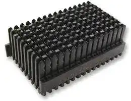
Connector, MULTIGIG RT, 144 Contacts, 1.8 mm, Receptacle, Press Fit, 16 Rows
- Manufacturer: TE CONNECTIVITY
- Product type:
- Product Range:MULTIGIG RT Series; No. of Contacts:144Contacts; Pitch Spacing:1.8mm; Gender:Receptacle; Contact Termination Type:Press Fit; No. of Rows:16Rows; Row Pitch:1.8mm; Cont
- SVHC: Lead (21-Jan-2025)
- Gender: Receptacle
- Row Pitch: 1.8mm
- No. of Rows: 16Rows
- Pitch Spacing: 1.8mm
- Product Range: MULTIGIG RT
- Contact Plating: Gold Plated Contacts
- No. of Contacts: 144Contacts
- Contact Material: Phosphor Bronze
- Contact Termination Type: Press Fit
- Card Edge / Backplane Connector Type: Backplane
| Delivery and price | |
|---|---|
| Units per pack | 25 |
| Price | 23.75 € |
| Current stock | 200+ |
| Lead time | 30 days |
**108-2072**

Product Specification

10 Sep 12   Rev E

## **MULTIGIG RT* Signal Connectors, Tiers 1 and 2, RT2 Mezzanine, and RT2 Ruggedized**

## **1. SCOPE**

## 1.1. Content

This specification covers performance, tests and quality requirements for the TE Connectivity (TE) MULTIGIG RT* Signal connector system which uses a modular concept and interconnects two printed circuit boards. Both receptacle and plug connectors are connected to the printed circuit boards with plated thru-hole compliant press-fit leads. The connector system is designed to perform at two different signal transmission performance levels which are identified by the “Tier” designator. Although signal transmission performance levels vary between the “Tiers” of product, the mechanical and environmental requirements contained in this specification apply to all.

## 1.2. Qualification

When tests are performed on the subject product line, procedures specified in Figure 1 shall be used. All inspections shall be performed using the applicable inspection plan and product drawing.

## 1.3. Qualification Test Results

Successful qualification testing on Tier 1 product was completed on 14Aug02. Successful qualification testing on Tier 2 product was completed on 31Jan04. Successful qualification testing on RT2 Mezzanine product was completed on 11Nov07.  Successful qualification testing on the RT2 Ruggedized product was completed 20Aug2012.  The Qualification Test Report number for this testing is 501-544. This documentation is on file at and available from Engineering Practices and Standards (EPS).

## **2. APPLICABLE DOCUMENTS**

The following documents form a part of this specification to the extent specified herein. Unless otherwise specified, the latest edition of the document applies. In the event of conflict between the requirements of this specification and the product drawing, the product drawing shall take precedence. In the event of conflict between the requirements of this specification and the referenced documents, this specification shall take precedence.

## 2.1.

## Tyco Electronics Documents

   - 109 Series:  Test Specifications as indicated in Figure 1

   - 109-197:  Test Specification (AMP Test Specifications vs EIA and IEC Test Methods)

   - 501-544:  Qualification Test Report (MULTIGIG RT* Signal Connectors, Tiers 1 and 2, RT2 Mezzanine, and RT2 Ruggedized.)

- 2.2.

## Commercial Documents

- Bellcore GR-1217:  Generic Requirements for Separable Electrical Connectors Used in Telecommunications Hardware

- EIA-364:  Electrical Connector/Socket Test Procedures Including Environmental Classifications

©2012 Tyco Electronics Corporation, a TE Connectivity Ltd. company All Rights Reserved | Indicates Change

1 of 11

*Trademark.  TE Connectivity, TE connectivity (logo), and TE (logo) are trademarks.  Other logos, product and/or company names may be trademarks of their respective owners.

108-2072

## **3. REQUIREMENTS**

- 3.1. Design and Construction

Product shall be of the design, construction and physical dimensions specified on the applicable product drawing.

## 3.2. Materials

Materials used in the construction of this product shall be as specified on the applicable product drawing.

## 3.3. Ratings

   - Operating Voltage: 50 volts AC peak or DC

   - Current: 1 ampere at <30°C (single circuit, free air)

   - Temperature: -55 to 105°C

- 3.4.

- Performance and Test Description

Product is designed to meet the electrical, mechanical and environmental performance requirements specified in Figure 1. Unless otherwise specified, all tests shall be performed at ambient environmental conditions.

- 3.5. Test Requirements and Procedures Summary

|Final examination of product.|drawing.<br>Meets visual requirements.<br>ELECTRICAL|Visual and dimensional (C of C)<br>inspection per product drawing.<br>EIA-364-18.<br>Visual inspection.|
|---|---|---|
|Low level contact resistance, circuit. 80 milliohms maximum initial.|Low level contact resistance, circuit. 80 milliohms maximum initial.<br>5 milliohms maximum average<br>increase.<br>10 milliohms maximum individual<br>increase.|EIA-364-23.<br>Subject specimens to 100<br>milliamperes maximum and 20<br>millivolts maximum open circuit<br>voltage.<br>See Figure 3.|
|Low level contact resistance,<br>compliant pin.|1 milliohm maximum initial.<br>1 milliohm maximum change.|EIA-364-23.<br>Subject specimens to 100<br>milliamperes maximum and 20<br>millivolts maximum open circuit<br>voltage.<br>See Figure 4.|
|Insulation resistance.|1000 megohms minimum.|EIA-364-21.<br>Test between any adjacent pair of<br>signal contacts, or from any signal<br>contact to an adjacent ground pin<br>of mated specimens at 100 volts<br>DC.|


Figure 1 (continued)

2 of 11

Rev E

108-2072

|Temperature rise vs current.|30°C maximum temperature rise at<br>1 ampere load, single circuit in free<br>air using thermography.<br>MECHANICAL|EIA-364-70, Method 1.<br>Stabilize at a single current level<br>until 3 readings at 5 minute intervals<br>are within 1°C.|
|---|---|---|
|Vibration, sinusoidal.|No discontinuities of 1 microsecond<br>or longer duration.<br>See Note.|EIA-364-28, Test Condition II.<br>Subject mated specimens to 10-<br>500-10 Hz traversed in 15 minutes<br>with 1.5 mm [.06 in] maximum total<br>excursion. Two hours in each of 3<br>mutually perpendicular planes.|
|Mechanical shock.|No discontinuities of 1 microsecond<br>or longer duration.<br>See Note.|EIA-364-27, Method H.<br>Subject mated specimens to 30 G's<br>half-sine shock pulses of 11<br>milliseconds duration. Three shocks<br>in each direction applied along 3<br>mutually perpendicular planes, 18<br>total shocks.|
|Durability.|See Note.|EIA-364-9.<br>Mate and unmate specimens for<br>200 cycles at a maximum rate of<br>500 cycles per hour.|
|Mating force.|0.75 N [2.7 ozf] maximum per<br>contact. Average for entire<br>connector.|EIA-364-13.<br>Measure force necessary to mate<br>specimens at a maximum rate of<br>12.7 mm [.5 in] per minute.|
|Unmating force.|0.15 N [.54 ozf] minimum per<br>contact. Average for entire<br>connector.|EIA-364-13.<br>Measure force necessary to unmate<br>specimens at a maximum rate of<br>12.7 mm [.5 in] per minute.|
|Compliant pin insertion.|31 N [7 lbf] maximum per pin<br>average.|AMP Spec 109-41.<br>Measure force necessary to<br>correctly apply a connector<br>assembly to a printed circuit board<br>at a maximum rate of 12.7 mm [.5<br>in] per minute.|
|Compliant pin retention.|13.35 N [3 lbf] minimum.|AMP Spec 109-30.<br>Measure force necessary to unseat<br>a single pin in a correctly applied<br>connector assembly from its printed<br>circuit board hole at a maximum<br>rate of 12.7 mm [.5 in] per minute.|


Figure 1 (continued)

3 of 11

Rev E

108-2072

|Test Description<br>Minute disturbance.|Requirement<br>See Note.<br>ENVIRONMENTAL|Procedure<br>Unmate and mate specimens a<br>distance of approximately 0.1 mm<br>[.004 in].|
|---|---|---|
|Thermal shock.|See Note.|EIA-364-32, Test Condition VII.<br>Subject mated specimens to 5<br>cycles between -55 and 105°C.|
|Humidity/temperature cycling.|See Note.|EIA-364-31, Method III.<br>Subject mated specimens to 10<br>cycles (10 days) between 25 and<br>65°C at 80 to 100% RH.|
|Temperature life.|See Note.|EIA-364-17, Method A, Test<br>Condition 4, Test Time Condition C.<br>Subject mated specimens to 105°C<br>for 500 hours.|
|Mixed flowing gas.|See Note.|EIA-364-65, Class IIA (4 gas).<br>Subject mated and unmated<br>specimens to environmental Class<br>IIA for 20 days.|
|Dust contamination.|See Note.|EIA-364-91.<br>Subject unmated specimens to dust<br>contamination for 1 hour.|


**NOTE** _Shall meet visual requirements, show no physical damage, and meet requirements of additional tests as specified in the Product Qualification and Requalification Test Sequence shown in Figure 2._

Figure 1 (end)

4 of 11

Rev E

B =/E=I

108-2072

- 3.6. Product Qualification and Requalification Test Sequence

   - A. Tier 1 Product

|Test or Examination|Test Group (a)|Test Group (a)|Test Group (a)|Test Group (a)|Test Group (a)|
|---|---|---|---|---|---|
||1|2|3|4|5|
||Test Sequence (b)|||||
|Initial examination of product|1|1|1|1|1|
|Low level contact resistance, circuit|3,7,10,15|3,7,9,12|2,5,7,10|2,5,7,9,12,14,16,19||
|Low level contact resistance, compliant pin (c)|4,16|4,13|3,11|3,10,17||
|Insulation resistance|5,13|14||||
|Withstanding voltage|6,14|15||||
|Temperature rise vs current|||||2|
|Vibration|||8|||
|Mechanical shock|||9|||
|Durability||6|4|4,18(d)||
|Mating force|2,12|2,17|13|||
|Unmating force|8,11|5,16|12|||
|Compliant pin insertion|||||3|
|Compliant pin retention|18|18|14|20|4|
|Minute disturbance||||15||
|Thermal shock||10||||
|Humidity-temperature cycling||11||||
|Temperature life|9|||||
|Mixed flowing gas||||6(e),8(e),11(f),13(f)||
|Dust contamination||8|6|||
|Final examination of product|17|19|15|21||


- **NOTE** _(a) See paragraph 4.1.A._

   - _(b) Numbers indicate sequence in which tests are performed._

   - _(c) Compliant pin design requires special test printed circuit board for low level contact resistance data collection. Separate, parallel test groups to be supplied where this data is required._

   - _(d) Perform 100 cycles of durability before, and 100 cycles after mixed flowing gas testing._

   - _(e) Exposure interval of 5 days with specimens unmated._

   - _(f) Exposure interval of 5 days with specimens mated._

Figure 2A

5 of 11

Rev E

B =/E=I

108-2072

## B. Tier 2 Product

|Test or Examination|Test Group (a)|Test Group (a)|Test Group (a)|Test Group (a)|Test Group (a)|
|---|---|---|---|---|---|
||1|2|3|4|5|
||Test Sequence (b)|||||
|Initial examination of product|1|1|1|1|1|
|Low level contact resistance, circuit|3,9,13|3,9,11,14|2,5,7,10|2,5,7,9,12,14,16,18||
|Low level contact resistance, compliant pin (c)|4,10|4,17|3,11|3,10,19||
|Insulation resistance|5,14|5,18||||
|Withstanding voltage|6,15|6,19||||
|Temperature rise vs current|||||2|
|Vibration|||8|||
|Mechanical shock|||9|||
|Durability||8|4|4,17(d)||
|Mating force|2,12|2,16|13|||
|Unmating force|7,11|7,15|12|||
|Compliant pin insertion|||||3|
|Compliant pin retention|16|20|14|20|4|
|Minute disturbance||||15||
|Thermal shock||12||||
|Humidity-temperature cycling||13||||
|Temperature life|8|||||
|Mixed flowing gas||||6(e),8(e),11(f),13(f)||
|Dust contamination||10|6|||
|Final examination of product|17|21|15|21|5|


- **NOTE** _(a) See paragraph 4.1.A._

   - _(b) Numbers indicate sequence in which tests are performed._

   - _(c) Compliant pin design requires special test printed circuit board for low level contact resistance data collection. Separate, parallel test groups to be supplied where this data is required._

   - _(d) Perform 100 cycles of durability before, and 100 cycles after mixed flowing gas testing._

   - _(e) Exposure interval of 5 days with specimens unmated._

   - _(f) Exposure interval of 5 days with specimens mated._

## Figure 2B

6 of 11

Rev E

108-2072

## C. RT2 Mezzanine Product

||Test Group (a)|Test Group (a)|
|---|---|---|
|Test or Examination|1|2|
||Test Sequence (b)||
|Initial examination ofproduct|1|1|
|Low level contact resistance, circuit|2,4,6,9|2,4,6,8,10,12,14,16|
|Vibration|7||
|Mechanical shock|8||
|Durability|3|3,15(c)|
|Matingforce|10||
|Unmatingforce|11||
|Minute disturbance||13|
|Mixed flowing gas||5(d),7(d),9(e),11(e)|
|Dust contamination|5||
|Final examination ofproduct|12|17|


**NOTE**

- _(a) See paragraph 4.1.A._

- _(b) Numbers indicate sequence in which tests are performed._

- _(c) Perform 100 cycles of durability before, and 100 cycles after mixed flowing gas testing._

- _(d) Exposure interval of 5 days with specimens unmated._

- _(e) Exposure interval of 5 days with specimens mated._

Figure 2C

7 of 11

Rev E

108-2072

## D. RT2 Ruggedized Product

|||Test Groups(a)|Test Groups(a)|
|---|---|---|---|
|Test or Examination|1|2|3|
|||Test Sequence (b)||
|Initial examination ofproduct|1|1|1|
|Low level contact resistance, circuit|3,6|2,4,6,9|2,4,6,8,10,12,14,16|
|Vibration||7||
|Mechanical shock||8||
|Durability||3|3,15(c)|
|Matingforce|2,8|11||
|Unmatingforce|4,7|10||
|Minute disturbance|||13|
|Temperature life|5|||
|Mixed flowing gas|||5(d),7(d),9(e),11(e)|
|Dust contamination||5||
|Final examination ofproduct|9|12|17|


**NOTE** _(a) See Paragraph 4.1.A._

_(b) Numbers indicate sequence in which tests are performed._

_(c) Perform 100 cycles of durability before, and 100 cycles after mixed flowing gas testing. (d) Exposure interval of 5 days with specimens unmated._

_(e) Exposure interval of 5 days with specimens mated._

Figure 2D

8 of 11

Rev E

108-2072

## **4. QUALITY ASSURANCE PROVISIONS**

## 4.1. Qualification Testing

## A. Specimen Selection

## 1. Tier 1 Product

Specimens shall be prepared in accordance with applicable Instruction Sheets and shall be selected at random from current production. Each test group shall consist of 8 male and 8 female connector assemblies. Low level contact resistance circuit data, where tested, shall be collected and evaluated from a minimum of 100 circuits chosen at random from those assemblies. Low level contact resistance compliant pin data, where tested, shall be collected and evaluated from a minimum of 50 pins chosen at random from those assemblies.

## 2. Tier 2 Product

Specimens shall be prepared in accordance with applicable Instruction Sheets and shall be selected at random from current production. Test groups 1 and 2 shall each consist of 12 male and 12 female connector assemblies. Test groups 3 and 4 shall each consist of 8 male and 8 female connector assemblies. Test group 5 shall consist of 7 male and 7 female connector assemblies. Low level contact resistance circuit data, where tested, shall be collected and evaluated from a minimum of 96 circuits chosen at random from those assemblies. Low level contact resistance compliant pin data, where tested, shall be collected and evaluated from a minimum of 100 pins chosen at random from those assemblies.

## 3. RT2 Mezzanine Product

Specimens shall be prepared in accordance with applicable Instruction Sheets and shall be selected at random from current production. Each test group shall consist of 4, 42 mm stack height Mezzanine connectors and 8, 20.3 mm MULTIGIG RT2 vertical receptacle assembly backplane connectors. Low level contact resistance circuit data, where tested, shall be collected and evaluated from a minimum of 100 circuits chosen at random from those assemblies.

## 4. RT2 Ruggedized

Specimens shall be prepared in accordance with applicable Instruction Sheets and shall be selected at random from current production. Each test group shall consist of 5 male and 5 female connector assemblies. Low level contact resistance circuit data, where tested, shall be collected and evaluated from a minimum of 100 circuits chosen at random from those assemblies.

## B. Test Sequence

Qualification inspection shall be verified by testing specimens as specified in Figures 2A, 2B, 2C, and 2D.

## 4.2. Requalification Testing

If changes significantly affecting form, fit or function are made to the product or manufacturing process, product assurance shall coordinate requalification testing, consisting of all or part of the original testing sequence as determined by development/product, quality and reliability engineering.

9 of 11

Rev E

—TEDpBp

108-2072

## 4.3. Acceptance

Acceptance is based on verification that the product meets the requirements of Figure 1. Failures attributed to equipment, test setup or operator deficiencies shall not disqualify the product. If product failure occurs, corrective action shall be taken and specimens resubmitted for qualification. Testing to confirm corrective action is required before resubmittal.

## 4.4. Quality Conformance Inspection

The applicable quality inspection plan shall specify the sampling acceptable quality level to be used.

**==> picture [253 x 118] intentionally omitted <==**

**----- Start of picture text -----**<br>
Power<br>A Supply<br>Termination Resistance<br>Measurement Points<br>**----- End of picture text -----**<br>


Dimensional and functional requirements shall be in accordance with the applicable product drawing and this specification.

## **Figure 3**

## **Low Level Contact Resistance Measurement Points (Circuit)**

10 of 11

Rev E

108-2072

**==> picture [322 x 147] intentionally omitted <==**

**----- Start of picture text -----**<br>
Termination Resistance<br>Measurement Points<br>Power<br>Supply<br>il)1 ‘saeciaiin 3<br>Termination Resistance<br>Measurement Points<br>Power<br>Supply<br>**----- End of picture text -----**<br>


**Figure 4 Low Level Contact Resistance Measurement Points (Compliant Pin)**

11 of 11

Rev E
Updated at June 7, 2026
TE Connectivity is a globally recognized engineering and manufacturing leader, specializing in highly reliable connectivity and sensing solutions. Renowned for innovation and durability, their components are engineered to perform in the most demanding environments, supporting critical advancements in industrial equipment, data communications, and automotive systems. Our extensive selection of TE Connectivity products is anchored by their industry-leading connector portfolio. We carry a comprehensive array of terminal blocks and accessories, including wire-to-board, pluggable, standard, and barrier configurations, alongside robust backplane connectors designed to ensure secure and efficient power and data transmission in complex circuit designs. Beyond physical connections, TE Connectivity is a premier manufacturer of precision sensors, antennas, and electromechanical switching components. Our inventory features a wide variety of RF antennas and highly accurate pressure, temperature, and force transducers. Additionally, we provide an expansive range of TE's dependable relays, encompassing automotive, power, and signal variants, alongside essential passive components like shielding gaskets and RF inductors to fully support your engineering requirements.
About Novapart
Novapart is a B2B electronic component broker specialising in stock shortages and cost reduction. We source hard-to-find parts and identify compliant alternatives across a catalogue of 410,000+ components from 500+ manufacturers.
Learn more →Stock Shortage Specialist
When a component is unavailable, discontinued or has an unacceptable lead time, we tap into our network of vetted European and Asian distributors to source what you need — without compromising on quality or traceability.
Request a quote →Compliant Alternatives
We identify pin-to-pin, electrically equivalent substitutes that meet the same certifications (RoHS, AEC-Q100, REACH) as your original specification — validated against datasheets, not just part numbers. Often at a lower cost.
BOM Analysis service →