
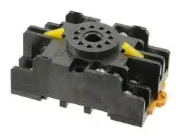


11PFA
Relay Socket, DIN Rail, Screw, 11 Pins, PFA Series
- Manufacturer: OMRON INDUSTRIAL AUTOMATION
- Product type: Relay Sockets
- SVHC: To Be Advised
- No. of Pins: 11Pins
- Product Range: PFA Series
- Current Rating: -
- Voltage Rating: -
- Socket Mounting: DIN Rail
- Socket Terminals: Screw
| Delivery and price | |
|---|---|
| Units per pack | 20 |
| Price | 16.61 € |
| Current stock | 10+ |
| Lead time | 30 days |
**Latching Relay MMK**

CSM_MMK_OEE_DS_E_1_1

## **Mechanically Latching Relays Based on the MM Power Relay**

- Low power consumption due to mechanical latch for economic operation.

- Relays with mixed coil specifications can be produced (e.g., AC set coil and DC reset coil).

- Operational response fast enough to enable pulse signal power applications.

- Ambient operating temperature: –10°C to 55°C.

Refer to _Safety Precautions for All Relays_ .

## **Orderin Information g**

|**Type**|**Contact form**|**Cased**|
|---|---|---|
|||**Plug-in (octal pins) terminals**|
|**Standard**|DPDT|MM2KP|
||3PDT|MM3KP|
||4PDT|---|
||DPDT+DPST-NO|MM4KP|
|**DC-switching**|DPDT|MM2XKP|
||3PDT|MM3XKP|
||4PDT|---|
||DPDT+DPST-NO|MM4XKP|
|**Conforming to auxiliary power**<br>**relay specifications**|DPDT+DPST-NO|MM4KP-JD<br>MM4XKP-JD|


## **Models Conforming to Auxiliary Power Relay Specifications**

The MM4KP-JD and MM4XKP-JD satisfy the ratings of auxiliary relays provided in JEC-2500 (1987) standards for power protective relays specified by the Japan Electromechanical Commission. Furthermore, the MM4KP-JD and MM4XKP-JD satisfy the ratings of multi-contact relays provided in JEC-174D (1979) standards for power auxiliary relays.

These models work at operation level A specified by JEC-174D (1979) standards and the hot start of the relays is possible after the coils radiate heat.

In accordance with JEC-2500 (1987) standards, the coil of each model withstands a 130% DC load or 115% AC load.

**Note:** When ordering, add the rated coil voltage to the model number. Rated coil voltages are given in the coil ratings table.

Example: MM2KP, 6 VAC

Rated coil voltage

**1**

**MMK**

## ■ **Available Models**

**When your order, specify the rated voltage.**

## **- Cased Coils (Plug in Terminals)**

|**Type**|**Contact form**|**Relay model**|**Available rated voltage**|
|---|---|---|---|
|Standard|DP|MM2KP|6, 12, 24, 100/(110), 200/(220) VAC<br>12, 24, 48, 100/110, 125, 200/220 VDC|
||3P|MM3KP|24, 100/(110), 200/(220) VAC<br>6, 12, 24, 48, 100/110, 125, 200/220 VDC|
||4P|MM4KP|24, 100/(110), 200/(220) VAC<br>6, 12, 24, 48, 100/110, 125, 200/220 VDC|
|DC-switching|DP|MM2XKP|24, 100/(110), 200/(220) VAC<br>12, 24, 48, 100/110, 125, 200/220 VDC|
||3P|MM3XKP|100/(110), 200/(220) VAC<br>24, 48, 100/110, 125, 200/220 VDC|
||4P|MM4XKP|100/(110), 200/(220) VAC<br>6, 12, 24, 48, 100/110, 125, 200/220 VDC|
|Conforming to auxiliary power relay<br>specifications|4P|MM4KP-JD|24, 100/(110), 115, 200/(220) VAC<br>24, 100/110, 125, 200/220 VDC|
|Conforming to auxiliary power relay<br>specifications for DC-switching|4P|MM4XKP-JD|100/(110), 115, 200/(220) VAC<br>24, 48, 100/110, 125, 200/220 VDC|


## **Model Number Legend**

## **MM** @@ **K** @

1    2 3

## **1. Contact Form**

2: DPDT

3: 3PDT

4: DPDT+DPST-NO (cased type)

## **3. Terminal Shape**

P: Plug-in

**Note:** The suffix “JD” indicates models conforming to auxiliary power relay specifications.

**2. Type (see note)**

None: Standard

X: DC-switching

**==> picture [539 x 35] intentionally omitted <==**

**2**

**MMK**

## ■ **Accessories (Order Separately)**

## **Sockets**

|**Sockets**|||
|---|---|---|
|**Relay**|**DIN Track/Front-connecting Socket**|**Back-connecting Socket**|
||**Screw terminals**|**Solder terminals**|
|**MM2(X)KP**|11PFA|PL11|
|**MM3(X)KP**<br>**MM4(X)KP**|14PFA|PL15|
|**MM4(X)KP-JD**|14PFA|---|


## **S ecifications p**

## ■ **Coil Ratings**

## **Set Coil**

|**Set Coil**|**Set Coil**||||||||||
|---|---|---|---|---|---|---|---|---|---|---|
|**Rated**<br>**voltage (V)**||**Rated current (mA)**||||**Coil resistance**<br>**(**Ω**)**||**Set**<br>**volt.**|**Max**<br>**volt.**|**Power consumption**<br>**(VA or W)**|
|||**DP**||**3P, 4P**|||||||
|||**Cased**||**Cased**|||||||
|||**50 Hz**|**60 Hz**|**50 Hz**|**60 Hz**|**DP**|**3P, 4P**|**% of rated**<br>**voltage**|||
|AC|6|690|590|1,165<br>|1,000|1.1|0.46|80%<br>max.|110%|**Initial:**<br>DP: Approx. 6.2<br>3P, 4P: Approx. 12<br>**Rated:**<br>DP: Approx. 3.5<br>3P, 4P: Approx. 6|
||12|345|295|580<br>|500|4.7|1.9||||
||24|170|145|290<br>|250|19|8.2||||
||100/<br>(110)|41|35/40|70<br>|60/68|340|141||||
||200/<br>(220)|20.5|17.5/<br>20|35<br>|30/34|1,540|563||||
|DC|6|340||450||17.5|13.4|||DP: Approx. 2.1<br>3P, 4P: Approx. 2.7|
||12|176||220||68|54||||
||24|87||94||275|255||||
||48|41||52||1,180|930||||
||100/<br>110|17/19||22/24.5||5,750|4,500||||
||200/<br>220|8.6/9.5||11/12||23,200|18,000||||


- **Note: 1.** The rated current and coil resistance are measured at a coil temperature of 23°C with tolerances of +15%/–20% for AC rated current and ±15% for DC coil resistance.

   **2.** Performance characteristic data are measured at a coil temperature of 23°C.

   **3.** The AC coil resistance values are reference values.

   **4.** The maximum voltage is one that is applicable instantaneously to the Relay coil at an ambient temperature of 23°C and not continuously.

**==> picture [539 x 35] intentionally omitted <==**

**3**

**MMK**

## **Reset Coil**

|**Reset Coil**|**Reset Coil**|||||||
|---|---|---|---|---|---|---|---|
|**Rated voltage (V)**||**Rated current (mA)**||**Coil resistance**<br>**(**Ω**)**|**Reset voltage**|**Maximum voltage**|**Power consumption**<br>**(VA or W)**|
|||**50 Hz**|**60 Hz**||**% of rated voltage**|||
|AC|6|770|690|2.3|80% max.|110%|Initial: Approx. 6.5<br>Rated: Approx. 4.1|
||12|385|345|9.2||||
||24|191|170|35||||
||100/(110)|46|41/46|739||||
||200/(220)|23|20/23|3,030||||
|DC|6|422||14.2|||Approx. 2.8|
||12|215||56||||
||24|109||220||||
||48|58||832||||
||100/110|25/27||4,040||||
||200/220|12.2/13.5||16,330||||


- **Note: 1.** The rated current and coil resistance are measured at a coil temperature of 23°C with tolerances of +15%/–20% for AC rated current and ±15% for DC coil resistance.

   **2.** Performance characteristic data are measured at a coil temperature of 23°C.

   **3.** The AC coil resistance values are reference values.

   **4.** The maximum voltage is one that is applicable instantaneously to the Relay coil at an ambient temperature of 23°C and not continuously.

## **Coils (Conforming to Auxiliary Power Relay Specifications)**

|**Rated**<br>**voltage (V)**|**Rated**<br>**voltage (V)**|**Rated current (mA)**|**Rated current (mA)**|**Rated current (mA)**|**Rated current (mA)**|**Coil resistance**<br>**(**Ω**)**|**Coil resistance**<br>**(**Ω**)**|**Set**<br>**voltage**|**Reset**<br>**voltage**|**Max.**<br>**voltage**|**Opera-**<br>**tion**<br>**level**<br>**(JEC-**<br>**174D)**|**Power consumption (VA or W)**|**Power consumption (VA or W)**|**Power consumption (VA or W)**|**Power consumption (VA or W)**|
|---|---|---|---|---|---|---|---|---|---|---|---|---|---|---|---|
|||**Set coil**||**Reset coil**||**Set**<br>**coil**|**Reset**<br>**coil**|||||**Set coil**||**Reset coil**||
|||**50 Hz**|**60 Hz**|**50 Hz**|**60 Hz**|||**% of rated voltage**||||**Initial**|**Rated**|**Initial**|**Rated**|
|AC|24|245|210|191|170|8.5|35|80%<br>max.|80%<br>max.|110%|A|Approx.<br>6.3|Approx.<br>5.1|Approx.<br>6.5|Approx.<br>4.1|
||100/<br>(110)|58.5|51/58|46|41/46|150|739|||||||||
||110|53|46|42|37.3|182|835|||||||||
||115|51|44|40|35.7|210|885|||||||||
||200/<br>(220)|29|25.5/<br>29|23|20.5/<br>23|620|3,030|||||||||
||220|26.5|23|21|18.6|780|3,420|||||||||
|DC|24|94||109||255|220|||||Approx. 2.7||Approx. 2.8||
||48|52||58||930|832|||||||||
||100/<br>110|22/24.5||25/27||4,500|4,040|||||||||
||125|22||23.5||5,800|5,330|||||||||
||200/<br>220|11/12||12.2/13.5||18,000|16,330|||||||||


- **Note: 1.** The rated current and coil resistance are measured at a coil temperature of 23°C with tolerances of +15%/–20% for AC rated current and ±15% for DC coil resistance.

   **2.** The AC coil resistance and coil inductance values are for reference only.

   **3.** Performance characteristic data are measured at a coil temperature of 23°C.

   **4.** The maximum voltage is one that is applicable instantaneously to the Relay coil at an ambient temperature of 23°C and not continuously.

**==> picture [539 x 35] intentionally omitted <==**

**4**

**MMK**

## ■ **Contact Ratings**

## **Standard Relays**

|**Standard Relays**|||
|---|---|---|
|**Item**|**Cased Relays: MM2KP, MM3KP, MM4KP**||
||**Resistive load**<br>**(cos**φ**= 1)**|**Inductive load**<br>**(cos**φ**=0.4, L/R=7 ms)**|
|**Contact mechanism**|Single||
|**Contact material**|Ag||
|**Rated load**|5 A at 220 VAC<br>4 A at 24 VDC||
|**Rated carry current**|5 A||
|**Max. switching voltage**|250 VAC, 250 VDC||
|**Max. switching current**|5 A||
|**Max. switching power**<br>**(reference value)**|1,100 VA, 96W||


## **- DC switching Relays**

|**Item**|**Cased Relays: MM2XKP, MM3XKP, MM4XKP**|**Cased Relays: MM2XKP, MM3XKP, MM4XKP**|
|---|---|---|
||**Resistive load**<br>**(cos**φ**= 1)**|**Inductive load**<br>**(cos**φ**=0.4, L/R=7 ms)**|
|**Contact mechanism**|Single||
|**Contact material**|Ag||
|**Rated load**|5 A at 110 VDC||
|**Rated current flow**|5 A||
|**Max. switching voltage**|250 VAC, 250 VDC||
|**Max. switching current**|5 A||
|**Max. switching power**<br>**(reference value)**|700 W, 20 VA*1|600 W, 20 VA*1|


- **Note: 1.** When switching DC inductive loads at 125 V or more, an unstable region exists for a switching current of between 0.5 and

      - 2.5 A. The Relay will not turn OFF in this region. Use a switching current of 0.5 A or less when switching 125 VDC or more.

   **2.** If L/R exceeds 7 ms when switching DC inductive loads, an arc-breaking time of up to 50 ms must be considered in application and the circuit must be designed to ensure that an arc-breaking time of 50 ms is not exceeded.

   - *1. Refer to Switching an _Switching an AC Load with a DC-switching Model (“X” Model)_ on page 12.

## **Contacts (Conforming to Auxiliary Power Relay Specifications)**

|**Item**|**MM4KP-JD**|**MM4KP-JD**|**MM4XKP-JD**|**MM4XKP-JD**|
|---|---|---|---|---|
||**Resistive load**<br>**(cos**φ**= 1)**|**Inductive load**<br>**(cos**φ**= 0.4, L/R= 7 ms)**|**Resistive load**<br>**(cos**φ**= 1)**|**Inductive load**<br>**(cos**φ**= 0.4, L/R= 7 ms)**|
|**Contact mechanism**|Single||||
|**Contact material**|Ag||||
|**Rated load**|5 A at 220 VAC, 4 A at 24 VDC||5 A at 110 VDC||
|**Rated carry current**|5 A||||
|**Max. switching voltage**|250 VAC, 250 VDC||||
|**Max. switching current**|5 A||||


- **Note: 1.** When switching DC inductive loads at 125 V or more, an unstable region exists for a switching current of between 0.5 and

      - 2.5 A. The Relay will not turn OFF in this region. Use a switching current of 0.5 A or less when switching 125 VDC or more.

   **2.** If L/R exceeds 7 ms when switching DC inductive loads, an arc-breaking time of up to 50 ms must be considered in application and the circuit must be designed to ensure that an arc-breaking time of 50 ms is not exceeded.

**==> picture [539 x 35] intentionally omitted <==**

**5**

**MMK**

## ■ **Characteristics**

|■**Characteristics**||
|---|---|
|**Contact resistance (see note 2)**|50 mΩmax.|
|**Set time (see note 3)**|AC: 30 ms max.; DC: 60 ms max. (minimum pulse width for AC and DC: 100 ms)|
|**Reset time (see note 3)**|30 ms max. (minimum pulse width for AC and DC: 100 ms)|
|**Max. operating frequency**|Mechanical:<br>1,800 operations/hr<br>Electrical:<br>1,800 operations/hr (under rated load)|
|**Insulation resistance (see note 4)**|100 MΩmin. (at 500 VDC)|
|**Dielectric strength**|1,500 VAC, 50/60 Hz for 1 min between contacts of same polarity<br>2,000 VAC, 50/60 Hz for 1 min between contacts of different polarity, between contacts and coil, and<br>between set and reset coils|
|**Vibration resistance**|Destruction:<br>10 to 55 to 10 Hz, 0.375 mm single amplitude (0.75 mm double amplitude)<br>Malfunction:<br>10 to 35 to 10 Hz, 0.5 mm single amplitude (1.0 mm double amplitude)|
|**Shock resistance**|Destruction:<br>500 m/s2<br>Malfunction:<br>50 m/s2|
|**Endurance**|Mechanical:<br>2,500,000 operations min. (at 1,800 operations/hr)<br>Electrical:<br>500,000 operations min. (at 1,800 operations/hr under rated load) (see note 5)|
|**Error rate (level P)**<br>**(Reference value)**<br>**(see note 6)**|10 mA at 5 VDC|
|**Ambient temperature**|Operating: –10°C to 55°C (with no icingor condensation)|
|**Ambient humidity**|Operating: 5% to 85%|
|**Weight**|Standard Relays<br>DC-switching Relays<br>MM2KP:<br>Approx. 375 g<br>MM2XKP:<br>Approx. 380 g<br>MM3KP:<br>Approx. 550 g<br>MM3XKP:<br>Approx. 555 g<br>MM4KP:<br>Approx. 570g<br>MM4XKP:<br>Approx. 580g|


- **Note: 1.** The data shown above are initial values.

   **2.** The contact resistance was measured with 1 A at 5 VDC using the voltage drop method.

   **3.** The set or reset time was measured with the rated voltage imposed with any contact bounce ignored at an ambient temperature of 23°C.

   **4.** The insulation resistance was measured with a 500-VDC megger applied to the same places as those used for checking the dielectric strength.

   **5.** The electrical endurance was measured at an ambient temperature of 23°C.

   **6.** This value was measured at a switching frequency of 60 operations per minute.

## ■ **Characteristics (Conforming to Auxiliary Power Relay Specifications)**

|**Vibration resistance**|Destruction:<br>10 to 55 to 10 Hz, 0.375 mm single amplitude (0.75 mm double amplitude)<br>Malfunction:<br>10 to 22 to 10 Hz, 0.5 mm single amplitude (1.0 mm double amplitude)|
|---|---|
|**Shock resistance**|Destruction:<br>300 m/s2<br>Malfunction:<br>30 m/s2|
|**Endurance**|Mechanical:<br>2,500,000 operations min. (at 1,800 operations/hr)<br>Electrical:<br>500,000 operations min. (at 1,800 operations/hr under rated load) (see note 2)|
|**Error rate (level P)**<br>**(Reference value)**<br>**(see note 3)**|10 mA at 5 VDC|
|**Ambient temperature**|Operating:<br>–10°C to 40°C (with no icingor condensation)|
|**Ambient humidity**|Operating:<br>5% to 85%|
|**Weight**|MM4KP-JD:<br>Approx. 570 g<br>MM4XKP-JD: Approx. 580g|


- **Note: 1.** The data shown above are initial values.

   **2.** The electrical endurance was measured at an ambient temperature of 23°C.

   **3.** This value was measured at a switching frequency of 60 operations per minute.

**==> picture [539 x 35] intentionally omitted <==**

**6**

**MMK**

## **En ineerin Data g g**

## ■ **Standard Relays**

## **Maximum Switching Power Cased Relays**

**==> picture [161 x 168] intentionally omitted <==**

**----- Start of picture text -----**<br>
MM @ KP<br>50<br>30<br>10 AC resistive load<br>5<br>3<br>AC inductive load<br>(cosφ = 0.4)<br>1<br>0.5 DC resistive load<br>0.3<br>DC inductive load<br>(L/R = 7 ms)<br>0.1<br>5 10 30 50 100 300 500 1,000<br>Switching current (A)<br>Switching current (A)<br>**----- End of picture text -----**<br>


## **Endurance Curves**

## **Cased Relays**

**==> picture [172 x 151] intentionally omitted <==**

**----- Start of picture text -----**<br>
MM @ KP<br>1,000<br>500<br>300<br>220 VAC resistive load<br>Inductive load<br>100 (cosφ = 0.4)<br>50<br>30 24 VDC resistive load<br>Inductive load<br>L/R = 7 ms<br>0 1 2 3 4 5 6 7 8 9 10<br>Endurance (x10  operations)<br>4<br>**----- End of picture text -----**<br>


**==> picture [78 x 9] intentionally omitted <==**

**----- Start of picture text -----**<br>
Switching current (A)<br>**----- End of picture text -----**<br>


## ■ **DC-switching Relays**

## **Maximum Switching Power Cased Relays**

**==> picture [158 x 170] intentionally omitted <==**

**----- Start of picture text -----**<br>
MM @ XKP<br>50<br>30<br>10<br>DC resistive load<br>5<br>3<br>DC inductive load<br>1 L/R=7 ms<br>0.5<br>0.3<br>0.1<br>5 10 30 50 100 300 500 1,000<br>Switching voltage (V)<br>Switching current (A)<br>**----- End of picture text -----**<br>


**==> picture [539 x 35] intentionally omitted <==**

**7**

**MMK**

## **Endurance Curves Cased Relays**

**==> picture [180 x 169] intentionally omitted <==**

**----- Start of picture text -----**<br>
MM @ XKP<br>1,000<br>500<br>300<br>110 VDC<br>resistive load<br>100 Inductive load<br>L/R=7 ms<br>50<br>30<br>0 1 2 3 4 5 6 7 8 9 10<br>Switching current (A)<br>Endurance (x10  operations)<br>4<br>**----- End of picture text -----**<br>


## ■ **Relays Conforming to Auxiliary Power Relay Specifications**

**Maximum Switching Power MM4KP-JD**

**==> picture [50 x 7] intentionally omitted <==**

**----- Start of picture text -----**<br>
MMX4KP-JD<br>**----- End of picture text -----**<br>


**==> picture [392 x 339] intentionally omitted <==**

**----- Start of picture text -----**<br>
50 50<br>30 30<br>10 AC resistive load 10 DC resistive load<br>5 5<br>3 3<br>AC inductive<br>load DC inductive load<br>1 cosφ = 0.4 1 L/R = 7 ms<br>0.5 DC resistive load 0.5<br>0.3 0.3<br>DC inductive load<br>L/R = 7 ms<br>0.1 0.1<br>5 10 30 50 100 300 500 1,000 5 10 30 50 100 300 500 1,000<br>Switching voltage (V) Switching voltage (V)<br>Endurance Curves<br>MM4KP-JD MM4XKP-JD<br>1,000 1,000<br>500 500<br>300 300 110 VDC resistive load<br>220 VAC resistive load Inductive load<br>Inductive load L/R = 7 ms<br>cosφ = 0.4<br>100 100<br>50 50<br>30 24 VDC resistive load  30<br>Inductive load<br>L/R = 7 ms<br>0 1 2 3 4 5 6 7 8 9 10 0 1 2 3 4 5 6 7 8 9 10<br>Switching current (A) Switching current (A)<br>Switching current (A) Switching current (A)<br>Endurance (x 10  )<br>4 Endurance (x 10  )<br>4<br>**----- End of picture text -----**<br>


**==> picture [539 x 35] intentionally omitted <==**

**8**

**MMK**

## **Malfunctioning Shock**

## **Ambient Temperature vs. Set and Reset Voltage MM4KP AC (60 Hz)**

## **Ambient Temperature vs. Coil Temperature Rise MM4KP 110 VAC (60 Hz)**

**==> picture [496 x 358] intentionally omitted <==**

**----- Start of picture text -----**<br>
MM4(X)KP Y<br>MM4KP AC (60 Hz) MM4KP 110 VAC (60 Hz)  60 min. Reset<br>100 80<br>Number of Relays: 5 Set voltage Number of Relays: 5<br>Reset voltage 60 min. 60 min.<br>5.0A X Z<br>80 2.5A<br>60<br>0A<br>60<br>40<br>40<br>5.0A<br>Z' X'<br>20 2.5A 60 min. 60 min.<br>20 0A Contact carry current<br>Set coil<br>Reset coil  60 min.<br>0 0 Y' Unit: m/s [2]<br>-40 -20 0 20 40 60 80 -40 -20 0 20 40 60 80<br>Number of samples: 3<br>Ambient temperature (°C) Ambient temperature (°C)<br>Measurement conditions: Impose a shock of<br>50 m/s [2]  in the ±X, ±Y, and ±Z directions three<br>times each with the Relay energized and not<br>MM4KP DC MM4KP DC energized to check the shock values that cause<br>the Relay to malfunction.<br>100 40<br>Number of Relays: 5 Set voltage Number of Relays: 5<br>Reset voltage 5.0A<br>2.5A Shock direction<br>80 0A<br>30<br>60<br>20 5.0A<br>2.5A<br>40<br>0A<br>10<br>20<br>Contact carry current<br>Set coil<br>Reset coil<br>0 0<br>-40 -20 0 20 40 60 80 -40 -20 0 20 40 60 80<br>Ambient temperature (°C) Ambient temperature (°C)<br>Must-operate and reset voltage (%)<br>Must-operate and reset voltage (%)<br>C)Coil temperature rise (°<br>C)Coil temperature rise (°<br>**----- End of picture text -----**<br>


**==> picture [539 x 35] intentionally omitted <==**

**9**

**MMK**

## **Dimensions**

**Note:** All units are in millimeters unless otherwise indicated.

## ■ **Cased Relays with Plug-in Terminal**

**==> picture [491 x 207] intentionally omitted <==**

**----- Start of picture text -----**<br>
MM2(X)KP  Terminal Arrangement/<br>54.5 max.  Internal Connections<br>(see note) (Bottom View)<br>22<br>119 max.<br>3.5<br>7<br>5 Standard Relays  DC-switching Relays<br>MM2KP  MM2XKP<br>80.5 max.<br>64.5<br>max.<br>MM2KP  Note:  It is recommended that 55 mm min. is allowed<br>for this side because the MM2XKP has a<br>curved protective plate on the side.<br>Note:  Connect the common (C) to positive (+).<br>Make sure that all common connections are the<br>same in polarity. The markings of the common<br>connections on the casing all show "+" but the<br>polarity of the common connections can be ei-<br>ther all negative or all positive.<br>**----- End of picture text -----**<br>


**==> picture [289 x 132] intentionally omitted <==**

**----- Start of picture text -----**<br>
MM3(X)KP  72.5 max.<br>MM4(X)KP  (see note)<br>22 123 max.<br>3.5 7<br>80.5 max.<br>64.5<br>max.<br>MM4KP<br>**----- End of picture text -----**<br>


**Note:** It is recommended that 73 mm min. is allowed for this side because the MM3XKP and MM4XKP have a curved protective plate on the side.

**Terminal Arrangement/ Internal Connections (Bottom View)**

**==> picture [398 x 22] intentionally omitted <==**

**----- Start of picture text -----**<br>
Standard Relays  DC-switching Relays<br>MM3XKP<br>MM3KP  MM4KP  MM4XKP<br>**----- End of picture text -----**<br>


**Note:** Connect the common (C) to positive (+).

Make sure that all common connections are the same in polarity. The markings of the common connections on the casing all show "+" but the polarity of the common connections can be either all negative or all positive.

## **Cases on Models for Switching DC Loads**

As shown at the right, there are three holes with a 10-mm diameter in the case. Case Protective Plate

**==> picture [539 x 35] intentionally omitted <==**

**10**

**MMK**

## **MM4KP-JD**

**MM4XKP-JD**

**==> picture [208 x 184] intentionally omitted <==**

**----- Start of picture text -----**<br>
72.5 max.<br>22 123 max.<br>3.5 7<br>70.5 max.<br>64.5<br>max.<br>73 max.<br>22 123 max.<br>3.5 7<br>70.5 max.<br>64.5<br>max.<br>**----- End of picture text -----**<br>


**Terminal Arrangement/ Internal Connections (Bottom View)**

**Note:** The MM4KP-JD is DPDT and DPST-NO.

**Note:** The MM4XKP-JD is DPDT and DPSTNO. Make sure that all common connections are the same in polarity. The markings of the common connections on the casing all show "+" but the polarity of the common connections can be either all negative or all positive.

## **Accessories**

## ■ **Sockets**

**==> picture [512 x 135] intentionally omitted <==**

**----- Start of picture text -----**<br>
Relay model DIN Track/Front-connecting Socket Back-connecting Socket<br>Screw terminals Solder terminals<br>MM2(X)KP 11PFA  PL11<br>MM3(X)KP 14PFA PL15<br>MM4(X)KP<br>MM4(X)KP-JD 14PFA ---<br>**----- End of picture text -----**<br>


**Note:** When using the MM@KP-JD by itself, the PL15 Back-connecting Socket cannot be used.

## ■ **Height with Socket**

**DIN Track/Front-connecting Socket Back-connecting Socket**

**==> picture [389 x 82] intentionally omitted <==**

**----- Start of picture text -----**<br>
MM3KP<br>MM2KP   MM3XKP   MM3KP<br>MM2XKP  MM4KP   MM2KP   MM3XKP<br>MM4XKP  124 MM2XKP  128 MM4KP<br>151 147.5 155 MM4(X)KP-JD  151.5 MM4XKP<br>PL11 PL15<br>11PFA 14PFA<br>**----- End of picture text -----**<br>


**Note:** @PFA can be both track-mounted and screw-mounted.

**==> picture [539 x 35] intentionally omitted <==**

**11**

**MMK**

## **Safet Precautions y**

Refer to _Safety Precautions for All Relays_ .

## ■ **Mounting**

Make sure that the Relay is free from iron powder or iron core, otherwise the iron dust may adhere to the Relay. As a result the movable contact may not operate properly.

An arc may be generated between the contacts in switching operation. Be sure to keep combustible objects away from the Relay. If the arc will have a bad effect around the Relay, the use of a model with a casing is recommended.

A model switching DC load incorporates an insulation base with a small built-in permanent magnet. Be sure to keep magnets or ferrous objects away from the permanent magnet, otherwise the capacity of the maximum switching current may drop.

The PL Back-connecting Socket must be flush-mounted from the surface of the panel.

To minimize the influence of heat, separate Relays from each other by at least 20 mm for cooling when mounting multiple Relays together.

**==> picture [177 x 42] intentionally omitted <==**

**----- Start of picture text -----**<br>
Top 20 mm<br>min.<br>MMK  MMK<br>Normal mounting direction<br>Bottom<br>**----- End of picture text -----**<br>


Be sure to mount the Relay so that the movable contact is in the downward direction.

## ■ **Connection**

- When connecting a load to the contact terminals of a model for switching DC loads (“X” models), consider the polarity of the contact terminals so that the generated arcs on the adjacent poles will not collide. (For example, if the common connections of the Relay are all positive or all negative, no arc collision will occur.)

- Use proper crimp terminals or 1.2- to 2-mm-dia. single-conductor wire to connect screw terminals.

## **Screw Terminal Model**

Do not bend the coil terminals, otherwise the coil wire may be disconnected. Make sure that the tightening torque applied to each terminal is 1.27 N • m and the insertion force is 49 N for 10 s.

## **Solder Terminal Model**

Make sure that Relay terminals are free of flux or other foreign substance before soldering the Relay terminals. Finish soldering the Relay terminals quickly, otherwise the coil wire may be broken.

## ■ **Circuits**

- You cannot use single contact to demagnetize the set coil as shown below.

Load Latching Relay coil NC contact of the Relay

- NC contacts can remain open for a few milliseconds when the reset coil turns ON and OFF. NO contact can remain open for a few milliseconds when the set coil turns ON and OFF while the Relay is latched. Design your circuits to allow for this.

**==> picture [126 x 92] intentionally omitted <==**

**----- Start of picture text -----**<br>
MMK contact<br>(NC)<br>The contact<br>may fail to<br>hold itself.<br>Relay coil<br>**----- End of picture text -----**<br>


- Do not allow voltage to be applied simultaneously to both the set and reset coil. If voltage is applied simultaneously, the Relay will be set.

- There is no reason to apply voltage to Latching Relays continuously because they will latch properly with a single pulse of sufficient width. Continuously applying voltage will only waste power.

- A model for DC loads incorporates a permanent magnetic for arc suppression. Keep floppy disks away from the Relay, otherwise the data on the floppy disk may be damaged.

- Arcing when switching DC power can cause nitric gas to be generated. The case of the MM@XKP contains holes to allow the gas to escape. This, however, makes it possible for dust and dirt to enter the case. Be sure to use the MM@XKP in a suitable environment.

**==> picture [62 x 88] intentionally omitted <==**

## ■ **Switching an AC Load with a DC-switching Model (“X” Model)**

DC-switching Relays (“X” models) use a magnet to extinguish arcs. The polarity must be correct when you connect the switching section. However, if you connect an AC load, the positive and negative poles of the power supply alternate. This can cause short-circuits due to the collision of arcs that occur when the Relay turns OFF. Therefore, the switching capacity for an AC load is specified as 20 VA or less to prevent short circuits caused by arc collisions. Take sufficient caution if you switch an AC Load with a DC-switching model (“X” models).

## ■ **Refer to the technical guide on your OMRON website for technical descriptions and FAQs on the product.**

ALL DIMENSIONS SHOWN ARE IN MILLIMETERS.

To convert millimeters into inches, multiply by 0.03937. To convert grams into ounces, multiply by 0.03527.

In the interest of product improvement, specifications are subject to change without notice.

**==> picture [539 x 35] intentionally omitted <==**

**12**

## Terms and Conditions Agreement

## Read and understand this catalog.

Please read and understand this catalog before purchasing the products.  Please consult your OMRON representative if you have any questions or comments.

## Warranties.

(a) Exclusive Warranty. Omron’s exclusive warranty is that the Products will be free from defects in materials and workmanship for a period of twelve months from the date of sale by Omron (or such other period expressed in writing by Omron). Omron disclaims all other warranties, express or implied.

(b) Limitations. OMRON MAKES NO WARRANTY OR REPRESENTATION, EXPRESS OR IMPLIED, ABOUT NON-INFRINGEMENT, MERCHANTABILITY OR FITNESS FOR A PARTICULAR PURPOSE OF THE PRODUCTS. BUYER ACKNOWLEDGES THAT IT ALONE HAS DETERMINED THAT THE

PRODUCTS WILL SUITABLY MEET THE REQUIREMENTS OF THEIR INTENDED USE.

Omron further disclaims all warranties and responsibility of any type for claims or expenses based on infringement by the Products or otherwise of any intellectual property right. (c) Buyer Remedy. Omron’s sole obligation hereunder shall be, at Omron’s election, to (i) replace (in the form originally shipped with Buyer responsible for labor charges for removal or replacement thereof) the non-complying Product, (ii) repair the non-complying Product, or (iii) repay or credit Buyer an amount equal to the purchase price of the non-complying Product; provided that in no event shall Omron be responsible for warranty, repair, indemnity or any other claims or expenses regarding the Products unless Omron’s analysis confirms that the Products were properly handled, stored, installed and maintained and not subject to contamination, abuse, misuse or inappropriate modification. Return of any Products by Buyer must be approved in writing by Omron before shipment. Omron Companies shall not be liable for the suitability or unsuitability or the results from the use of Products in combination with any electrical or electronic components, circuits, system assemblies or any other materials or substances or environments. Any advice, recommendations or information given orally or in writing, are not to be construed as an amendment or addition to the above warranty.

See http://www.omron.com/global/ or contact your Omron representative for published information.

## Limitation on Liability; Etc.

OMRON COMPANIES SHALL NOT BE LIABLE FOR SPECIAL, INDIRECT, INCIDENTAL, OR CONSEQUENTIAL DAMAGES, LOSS OF PROFITS OR PRODUCTION OR COMMERCIAL LOSS IN ANY WAY CONNECTED WITH THE PRODUCTS, WHETHER SUCH CLAIM IS BASED IN CONTRACT, WARRANTY, NEGLIGENCE OR STRICT LIABILITY. Further, in no event shall liability of Omron Companies exceed the individual price of the Product on which liability is asserted.

## Suitability of Use.

Omron Companies shall not be responsible for conformity with any standards, codes or regulations which apply to the combination of the Product in the Buyer’s application or use of the Product. At Buyer’s request, Omron will provide applicable third party certification documents identifying ratings and limitations of use which apply to the Product. This information by itself is not sufficient for a complete determination of the suitability of the Product in combination with the end product, machine, system, or other application or use. Buyer shall be solely responsible for determining appropriateness of the particular Product with respect to Buyer’s application, product or system. Buyer shall take application responsibility in all cases.

NEVER USE THE PRODUCT FOR AN APPLICATION INVOLVING SERIOUS RISK TO LIFE OR PROPERTY OR IN LARGE QUANTITIES WITHOUT ENSURING THAT THE SYSTEM AS A WHOLE HAS BEEN DESIGNED TO ADDRESS THE RISKS, AND THAT THE OMRON PRODUCT(S) IS PROPERLY RATED AND INSTALLED FOR THE INTENDED USE WITHIN THE OVERALL EQUIPMENT OR SYSTEM.

## Programmable Products.

Omron Companies shall not be responsible for the user’s programming of a programmable Product, or any consequence thereof.

## Performance Data.

Data presented in Omron Company websites, catalogs and other materials is provided as a guide for the user in determining suitability and does not constitute a warranty. It may represent the result of Omron’s test conditions, and the user must correlate it to actual application requirements. Actual performance is subject to the Omron’s Warranty and Limitations of Liability.

## Change in Specifications.

Product specifications and accessories may be changed at any time based on improvements and other reasons. It is our practice to change part numbers when published ratings or features are changed, or when significant construction changes are made. However, some specifications of the Product may be changed without any notice. When in doubt, special part numbers may be assigned to fix or establish key specifications for your application. Please consult with your Omron’s representative at any time to confirm actual specifications of purchased Product.

## Errors and Omissions.

Information presented by Omron Companies has been checked and is believed to be accurate; however, no responsibility is assumed for clerical, typographical or proofreading errors or omissions.

**In the interest of product improvement, specifications are subject to change without notice.**

## **OMRON Corporation**

## **Industrial Automation Company**

2018.3

**http://www.ia.omron.com/**

(c)Copyright OMRON Corporation 2018 All Right Reserved.
Updated at June 6, 2026
With a legacy spanning over 80 years, Omron Industrial Automation is a globally recognized leader in the manufacture of advanced industrial control and automation components. Renowned for their reliability and engineering excellence, Omron delivers comprehensive solutions that enhance efficiency, machine safety, and precision across a wide range of manufacturing environments. Our extensive portfolio of Omron products is heavily focused on their industry-leading sensing and switching technologies. We offer a vast selection of sensors, excelling specifically in high-performance proximity sensors, light sensors, and temperature sensors. Complementing this range are robust switching solutions, featuring a deep inventory of power relays, solid-state relays, safety relays, and essential relay accessories designed for demanding operational requirements. Beyond sensing and switching, Omron is highly regarded for its precision automation and process control equipment. Our selection features highly accurate temperature controllers, versatile process controllers, and sophisticated panel displays and instrumentation. To support these fundamental systems, we also supply dependable Omron power supplies, notably AC/DC converters, alongside vital connectivity components like DIN rail terminal blocks to ensure secure, efficient, and complete industrial setups.
About Novapart
Novapart is a B2B electronic component broker specialising in stock shortages and cost reduction. We source hard-to-find parts and identify compliant alternatives across a catalogue of 410,000+ components from 500+ manufacturers.
Learn more →Stock Shortage Specialist
When a component is unavailable, discontinued or has an unacceptable lead time, we tap into our network of vetted European and Asian distributors to source what you need — without compromising on quality or traceability.
Request a quote →Compliant Alternatives
We identify pin-to-pin, electrically equivalent substitutes that meet the same certifications (RoHS, AEC-Q100, REACH) as your original specification — validated against datasheets, not just part numbers. Often at a lower cost.
BOM Analysis service →