
Image not available
Illustrative purposes only

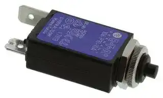
106-P10-10A
Thermal Circuit Breaker, 106 Series, 10 A, 1 Pole, 48 V, 240 V, Panel
⚠️ Reference pricing provided. In case of supply shortages, we will connect you with our trusted procurement partners to ensure your project's continuity.
- Manufacturer: ETA
- Product type: Thermal Circuit Breakers
- Product Range:106 Series; Current Rating:10A; No. of Poles:1 Pole; Voltage Rating V DC:48VDC; Voltage Rating VAC:240VAC; Circuit Breaker Mounting:Panel; SVHC:No SVHC (15-Jan-2018)
- SVHC: No SVHC (17-Jan-2022)
- No. of Poles: 1 Pole
- Product Range: 106 Series
- Current Rating: 10A
- Voltage Rating VAC: 240V
- Voltage Rating VDC: 48V
- Circuit Breaker Mounting: Panel
| Delivery and price | |
|---|---|
| Units per pack | 20 |
| Price | 13.9 € |
| Current stock | 100+ |
| Lead time | 30 days |
Datasheet

**Thermal Overcurrent Circuit Breakers 104/105/106-...**

**2**

## **Description** Ee

Miniaturised single pole thermal circuit breaker with push-to-reset, tease- free, trip-free, snap action mechanism (R-type TO CBE to EN 60934). Available in versions for PCB or panel mounting, snap-in or threadneck, or as an integral type. Approved to CBE standard EN 60934 (IEC 60934). For higher current ratings see type 1140.

## **Typical applications**

Motors, transformers, solenoids, printed circuit boards, hand-held machines and appliances, marine applications, caravans.

## **Ordering information**

**==> picture [225 x 8] intentionally omitted <==**

**----- Start of picture text -----**<br>
           104-...           105-...          106-...<br>**----- End of picture text -----**<br>


|**Type No.**<br>**104**PCB mounting type (-PR), or integral type (-P30/P10)<br>**105**snap-in panel mounting<br>**106**threadneck panel mounting with hex and knurled nut (hardware<br>bulk shipped with 5 pcs plus)<br>**106-M2**<br>threadneck panel mounting 3/8-27UNS with collar, hex nut and<br>knurled nut (hardware bulk shipped with 5 pcs plus)<br>~~a~~<br>~~o_§_.4odJ4.—_ ~~|**Type No.**<br>**104**PCB mounting type (-PR), or integral type (-P30/P10)<br>**105**snap-in panel mounting<br>**106**threadneck panel mounting with hex and knurled nut (hardware<br>bulk shipped with 5 pcs plus)<br>**106-M2**<br>threadneck panel mounting 3/8-27UNS with collar, hex nut and<br>knurled nut (hardware bulk shipped with 5 pcs plus)<br>~~a~~<br>~~o_§_.4odJ4.—_ ~~|**Technical data**<br>**For further detailsplease see chapter: Technical Information**<br>Voltage rating<br>AC 240 V; DC 48 V<br>(UL: AC 250 V;DC 48 V)<br> rrr|**Technical data**<br>**For further detailsplease see chapter: Technical Information**<br>Voltage rating<br>AC 240 V; DC 48 V<br>(UL: AC 250 V;DC 48 V)<br> rrr|
|---|---|---|---|
|**Terminal design**||Current ratings|0.05...10 A|
|**P10**blade terminals A6.3-0.8 (QC .250)<br>**P30**blade terminals A2.8-0.8 (QC .110)<br>**PR**solder terminal pins for PCB mounting (type 104 only)<br>**PR3**<br>PCB mounting (vertical), type 104 only<br>**Current ratings**<br>**0.05...10 A**||Auxiliarycircuit<br>Typical life<br>0.05...5 A 1,000 operations at 2 x I<br>DC 28 V:<br>6...8 A<br>10 A         50 o|0.5 A,AC 240 V,DC 28 V<br>0.05...5 A 1,000 operations at 2 x IN, inductive<br>3,000 operations at 2 x IN, inductive<br>500 operations at 2 x IN, inductive<br>10 A         50 operations at 2 x IN,inductive|
|||Ambient temperature        -20...+60 °C|erature        -20...+60 °C(-4...+140 °F)T 60|
|**106-**<br>**P30- 5 A**ordering example||Insulation co-ordination      rated impulse|Insulation co-ordination      rated impulse<br>pollution|


|**Technical data**<br>rrr|rrr|
|---|---|
|**For further detailsplease see cha**|**lease see chapter: Technical Information**|
|Voltage rating|AC 240 V; DC 48 V|
||(UL: AC 250 V;DC 48 V)|
|Current ratings|0.05...10 A|
|Auxiliarycircuit|0.5 A,AC 240 V,DC 28 V|
|Typical life<br>0.05...5 A 1,000 operations at 2 x I|0.05...5 A 1,000 operations at 2 x IN, inductive|
|DC 28 V:|3,000 operations at 2 x IN, inductive|
|6...8 A|500 operations at 2 x IN, inductive|
|10 A         50 o|10 A         50 operations at 2 x IN,inductive|
|Ambient temperature        -20...+60 °C|erature        -20...+60 °C(-4...+140 °F)T 60|
|Insulation co-ordination      rated impulse|Insulation co-ordination      rated impulse<br>pollution|
|(IEC 60664 and 60664 A)    withstand voltage|(IEC 60664 and 60664 A)    withstand voltage<br>degree<br>2.5 kV<br>2|
||reinforced insulation in operatingarea|
|Dielectric strength<br>(IEC 60664 and 60664A)|test voltage|
|operatingarea|AC 3,000 V|
|Insulation resistance|> 100 MΩ(DC 500 V)|
|Interrupting capacity Icn|0.05...8 A<br>6 x INAC|
||0.05...10 A<br>6 x INDC|
|Interrupting capacity<br>(UL 1077)|IN<br>UN<br>0.05...10 A<br>AC 250 V<br>2,000 A|
||0.05...10 A<br>DC 48 V<br>200 A|
|Degree of protection<br>(IEC 60529/DIN 40050)terminal area IP00<br> ~~lll~~|operating area IP40<br>terminal area IP00<br>~~lll~~|
|Vibration|10 g (57-500 Hz) ± 0.76 mm (10-57 Hz),|
||to IEC 60068-2-6, test Fc,|
||10 frequencycycles/axis|
|Shock<br>Corrosion<br>Humidity|25g (11 ms)to IEC 60068-2-27,test Ea<br>96 hours at 5 % salt mist,<br>to IEC 60068-2-11,test Ka<br>240 hours at 95 % RH,<br>to IEC 60068-2-78,test Cab|


The exact part number required can be built up from the table of choices shown above. Ordering references for optional features should be omitted if not required.

## **Preferred types**

|**Preferred types **|**Standard current ratings (A)**|**Standard current ratings (A)**|**Standard current ratings (A)**|**Standard current ratings (A)**|**Standard current ratings (A)**|**Standard current ratings (A)**|**Standard current ratings (A)**|**Standard current ratings (A)**|**Standard current ratings (A)**|**Standard current ratings (A)**|**Standard current ratings (A)**|**Standard current ratings (A)**|
|---|---|---|---|---|---|---|---|---|---|---|---|---|
||**0.5 **|**0.8**|**1**|**1.2 **|**1.5**|**2**|**3**|**4**|**5**|**6**|**8**|**10**|
|106-P10-|x|x|x|x|x|x|x|x|x|x|x|x|
|106-P30-|x|x|x|x|x|x|x|x|x|x|x|x|


|Degree of protection<br>operating area IP40<br>(IEC 60529/DIN 40050)terminal area IP00<br>Vibration<br>10 g (57-500 Hz) ± 0.76 mm (10-57 Hz),<br>**Standard current ratings and typical internal resistance values**<br>——&E__ ~~lll~~|
|---|
|to IEC 60068-2-6, test Fc,<br>**Current**<br>**Internal**<br>**Current**<br>**Internal**|
|10 frequencycycles/axis<br>**rating (A)**<br>**resistance (Ω)**<br>**rating (A)**<br>**resistance (Ω)**|
|Shock<br>25g (11 ms)to IEC 60068-2-27,test Ea<br>Corrosion<br>96 hours at 5 % salt mist,<br>to IEC 60068-2-11,test Ka<br>Humidity<br>240 hours at 95 % RH,<br>to IEC 60068-2-78,test Cab<br>0.05<br>285<br>1.8<br>0.28<br>0.08<br>134<br>2<br>0.25<br>0.1<br>81<br>2.5<br>0.18<br>~~Rs~~<br>~~Pe~~<br>~~a~~|
|Mass<br>approx. 10g<br>0.2<br>22<br>3<br>0.11<br>~~I~~|
|**Approvals**<br>0.3<br>8.7<br>3.5<br>0.076<br>0.4<br>5.5<br>4<br>0.067<br>0.5<br>3.3<br>4.5<br>0.051<br>0.6<br>2.45<br>5<br>≤ 0.05<br>0.7<br>1.6<br>6<br>≤ 0.05<br>0.8<br>1.45<br>7<br>≤ 0.05<br>1<br>0.9<br>8<br>≤ 0.05<br>1.2<br>0.6<br>10<br>≤ 0.05<br>1.5<br>0.4<br>**Authority**<br>**Voltage ratings**<br>**Current ratings**<br>VDE, SEV,<br>AC 240 V<br>DC 48 V<br>0.05...8 A<br>0.05...10 A<br>CSA, UL<br>AC 250 V; DC 48 V<br>0.05...10 A<br>~~a~~<br>~~|~~<br>~~|~~<br>~~|~~<br>~~|~~<br>~~a~~<br>~~a~~<br>~~a~~<br>~~es ee~~<br>~~es~~<br>~~ee ee ee~~<br>~~ee ee~~<br>~~ee~~<br>~~a~~|


2013/14

**www.e-t-a.de**

**2** - 15

**Thermal Overcurrent Circuit Breakers 104/105/106-...**

## **Dimensions**

**2**

**==> picture [512 x 653] intentionally omitted <==**

**----- Start of picture text -----**<br>
104-PR 104-P30<br>ø7<br>ø4 .276<br>.157 ø4<br>.157<br>PCB mounting holes<br>104-PR104-PR-A30.05...6 A0.5 104-PR7...10 A0.5 hole for mounting screw M2 usable depth 4.5 mm (.177 in.) 6.5 blade terminalsDIN 46244-A2.8-0.8(QC .110) cut-out dimensions<br>terminal design for .020 .020 .256 6.5<br>correct stand-off distances .256<br>1 0.8<br>.039 .031<br>9<br>.354 19<br>1 3 2 1 2 .748<br>9.1<br>.358 8±0.2 104-P30<br>17.5.689 .315±.008 9.5 ø1.5 9.5 7...10 A<br>19.2 .374 .059 .374<br>.756<br>17.5 8±0.2<br>21<br>.827 .689 .315±.008<br>104-PR3<br>0.05...6 A<br>105-P30<br>ø7<br>ø4 ø7<br>.276<br>ø4 .157 .276<br>.157<br>0.8 .1574 .0471.2 .74819 blade terminalsDIN 46244-A2.8-0.8 .43311<br>.031 15.4 0.9 (QC .110)<br>.606 1.2 .035 panel cut-out<br>a<br>.047<br>12<br>.472<br>PCB mounting holes 25<br>hole for mounting screw M2x5 0.05...6 A .984<br>6.5 7.7<br>.256 .303<br>d a b<br>mm inch mm inch<br>0.8 .031 21.9 .862 11.3  [+0.3]<br>.3589.1 19.2 .60615.4 2-31.01.5 .079-.118.039.059 2222.122.2 .866.870.874 .445  [+.012]<br>.756<br>105-P3<br>7...10 A 07...10 A<br>5.4<br>.213<br>7...10 A<br>7.7<br>5.4 4 .303<br>.213 .157<br>OFF  ON OFF  ON<br>9.5 .374 9.5 .374<br>6.5 .256 6.5 .256<br>27.6 1.09 29.6 1.16 27.6 1.09 29.6 1.16<br>max. 3 max .118  1.2 .047 max. 3 max .118  1.2 .047<br>9.5 .374<br>3.5 .138<br>4.5 .177 ø1.5 .059 ø1.5 .059 11 .433 Ø 2.2 .087<br>30 1.18 30 1.18 7.3 .287<br>11 .433<br>OFF  ON<br> OFF ON 9.5 .374 2 .079<br>9.5 .374<br>6.5 .256<br>6.5 .256 27.6 1.09 29.6 1.16<br>27.6 1.09 29.6 1.17 max. 3 max. 118  1.2 .047<br>1.2 .047 6.2 .244<br>10 .394 9.5 .374<br>max. 3 max .118<br>14 .551<br>b<br>2.1 .083<br>11 .433<br>0.9 .035 d<br>4 .157<br>0.9 .035<br>**----- End of picture text -----**<br>


This is a metric design and millimeter dimensions take precedence ~~(~~[mm ] inch )

2013/14

**www.e-t-a.de**

**2** - 16

**2**

## **Thermal Overcurrent Circuit Breakers 104/105/106-...**

## **Installation drawings**

## **Dimensions**

**==> picture [511 x 553] intentionally omitted <==**

**----- Start of picture text -----**<br>
106-P30 104-… operating area<br>3/8-27UNS-2A<br>tightening torque max. 0.8 Nm<br>ø4<br>.157<br>8 mounting area 8<br>.315 .315<br>19<br>.748 11<br>15.7 blade terminalsDIN 46244-A2.8-0.8 .433 105-… operating area<br>.618 (QC .110)<br>SW14 mounting hole<br>.551<br>9 9.6- 0.1<br>.354 .378 - .004<br>106-P30<br>7...10 A<br>8 8<br>.315 mounting area .315<br>106-… operating area<br>106-M2<br>3/8-27UNS-2A<br>tightening torque max. 0.8 Nm<br>mounting hole<br>9.6- 0.1<br>.378 - .004<br>8 mounting area 8<br>Terminal design .315 .315<br>104/105/106-P10<br>0.05...6 A 7...10 A Internal connection diagrams<br>blade terminals<br>DIN 46244-A6.3-0.8 Types 104<br>(QC  .250) 105<br>6.3 106<br>.248 polarizing tooth<br>1<br> OFF  ON<br>13.5 .531 10.5 .413 7 .276<br>0.7 .028<br>27.6 1.09 .315 .315<br>max. 3 max .118  1.2 .047<br>9.5 .374<br>- 0.1 - .004<br>8.9 .350<br>8.8 .346<br>.315 .315<br>- 0.1 - .004<br>8.9 .350<br>.315 .315<br>10 .394<br>8 8<br>8 8<br>8 8<br>**----- End of picture text -----**<br>


**==> picture [68 x 107] intentionally omitted <==**

**----- Start of picture text -----**<br>
Types 104<br>105<br>106<br>1<br>2<br>**----- End of picture text -----**<br>


This is a metric design and millimeter dimensions take precedence ~~(~~[mm ] inch ~~)~~

2013/14

**www.e-t-a.de**

**2** - 17

**Thermal Overcurrent Circuit Breakers 104/105/106-...**

**2**

## **Typical time/current characteristics at +23 °C/+73.4 °F**

## **Accessories**

**==> picture [429 x 338] intentionally omitted <==**

**----- Start of picture text -----**<br>
10000 0.05 - 6 A<br>(type 106-... only)<br>7 - 10 A X 201 285 01  (IP64)<br>1000<br>100<br>Knurled nut 3/8", plastic (standard)<br>10 Y 307 117 02<br>ø15 3<br>.591 .118<br>1<br>0.1 3/8-27UNS-2B<br>1 2 4 6 8 10 20 30<br>… times rated current<br>The time/current characteristic curve depends on the ambient temperature<br>prevailing. In order to eliminate nuisance tripping, please multiply the<br>Hex nut 3/8", nickel-plated brass<br>circuit breaker current ratings by the derating factor shown below. See also  Y 300 192 01<br>section Technical information.<br>Ambient temperature °F°C -20-4 +14-10 +320 +73.4+23 +104+40 +122+50 +140+60 3/8-27UNS-2B .0982.5<br>Derating factor 0.76 0.84 0.92 1 1.08 1.16 1.24<br>SW14<br>.551<br>Trip time in seconds<br>**----- End of picture text -----**<br>


**==> picture [210 x 24] intentionally omitted <==**

**----- Start of picture text -----**<br>
Water splash cover (transparent)/knurled nut assembly<br>(type 106-... only)<br>X 201 285 01  (IP64)<br>**----- End of picture text -----**<br>


This is a metric design and millimeter dimensions take precedence ~~(~~[mm ] inch )

All dimensions without tolerances are for reference only. In the interest of improved design, performance and cost effectiveness the right to make changes in these specifications without notice is reserved.Product markings may not be exactly as the ordering codes. Errors and omissions excepted.

2013/14

**www.e-t-a.de**

**2** - 18
Updated at June 5, 2026
About Novapart
Novapart is a B2B electronic component broker specialising in stock shortages and cost reduction. We source hard-to-find parts and identify compliant alternatives across a catalogue of 410,000+ components from 500+ manufacturers.
Learn more →Stock Shortage Specialist
When a component is unavailable, discontinued or has an unacceptable lead time, we tap into our network of vetted European and Asian distributors to source what you need — without compromising on quality or traceability.
Request a quote →Compliant Alternatives
We identify pin-to-pin, electrically equivalent substitutes that meet the same certifications (RoHS, AEC-Q100, REACH) as your original specification — validated against datasheets, not just part numbers. Often at a lower cost.
BOM Analysis service →