
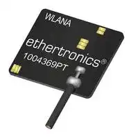


1004369PT-AA10L0100
RF Antenna, 5.15 to 5.825 GHz, WiFi/WLAN/Bluetooth/ZigBee/M2M, 3.7 dBi, Adhesive/MHF Connector
- Manufacturer: KYOCERA AVX
- Product type:
- Gain: 3.7dBi
- SVHC: No SVHC (17-Dec-2015)
- VSWR: 2
- Input Power: 2W
- Antenna Type: WiFi / WLAN / Bluetooth / ZigBee / M2M
- Frequency Max: 5.825GHz
- Frequency Min: 5.15GHz
- Product Range: 1004369PT Series
- Input Impedance: 50ohm
- Antenna Mounting: Adhesive / MHF Connector
- Antenna Polarisation: Mixed
| Delivery and price | |
|---|---|
| Units per pack | 1000 |
| Price | 1.03 € |
| Current stock | 10+ |
| Lead time | 30 days |
**DATASHEET** Part No. 1004369PT Product: Wi-Fi Mixed Polarized Tunable PCB 5 GHz Antenna

KYOCERA AVX 1004369PT is a versatile off-board PCB antenna ideal for 5 GHz Wi-Fi applications where off-board implementation is advantageous and necessary.

1004369PT is a mixed polarized antenna that offers easy on-the-go tuning capability right on the antenna face, that is ideal for prototyping. The tuned antenna can then be hardwired by KYOCERA AVX for mass production.

Custom cable and connector options are available. Please contact us for more information.

## **Electrical Specifications**

Typical Performance using 140 mm cable tested on PC-ABS

## **KEY BENEFITS**

## **Stay-in-Tune**

KYOCERA AVX antenna technology provides superior RF field containment, resulting in less interaction with surrounding components.

## **Quicker Time-to-Market**

By optimizing antenna size, performance and emissions, customer and regulatory specifications are more easily met.

## **Reliability**

Products are the latest RoHS version compliant

## **APPLICATIONS**

- Embedded • Telematics design • Tracking

- • Cellular, • Healthcare Headsets, • M2M, Tablets Industrial

- • Gateway, devices Access Point • SmartGrid

- • Handheld • OBD-II

|**Frequency**|**5.150 – 5.825 GHz**|
|---|---|
|Peak Gain|3.7 dBi|
|Average Efficiency|76%<br>2.0 :1 max<br>50 ohms unbalanced|
|VSWR Match||
|Feed Point Impedance||
|Polarization|Mixed|
|Power Handling|2 Watt CW|


## **Mechanical Specifications & Ordering Part Number**

|**Ordering Part #**|**1004369PT-AA80L0140**|
|---|---|
|Dimensions (mm)|18.0 x 12.8 x 0.4<br>(Height up to 2.2 at soldering point)|
|Weight (grams)|1.1|
|Cable/<br>Connector<br>(mm)|Cable/<br>Length: 140, Diameter: 1.37, Color: Black;<br>u.Fl compatible connector|
|Mounting|3M Adhesive on bottom side of antenna|
|Packaging|PE bags|


*Additional variations available with different cable lengths, colors and connectors.

**5 GHz KYOCERA AVX Embedded Antenna Specifications KYOCERA AVX produces a wide variety of standard and custom antennas to meet user needs.**

## **Typical VSWR, Efficiency and Peak Gain plots** Measured in free space with PC/ABS loading and 140 mm cable

**==> picture [62 x 8] intentionally omitted <==**

**----- Start of picture text -----**<br>
5 GHz VSWR<br>**----- End of picture text -----**<br>


**==> picture [120 x 9] intentionally omitted <==**

**----- Start of picture text -----**<br>
1004369PT-AA80L0140<br>**----- End of picture text -----**<br>


**==> picture [74 x 10] intentionally omitted <==**

**----- Start of picture text -----**<br>
5 GHz Efficiency<br>**----- End of picture text -----**<br>


5 GHz Peak Gain

## **5 GHz KYOCERA AVX Embedded Antenna Specifications KYOCERA AVX produces a wide variety of standard and custom antennas to meet user needs.**

## **Radiation Patterns Plots**

Measured with PC/ABS loading and 140 mm cable Typical Performance @ 5200 MHZ

## **Antenna Tuning Procedure**

This antenna has unique features enabling limited range RF tuning by solder bridging or cutting specified area. Ease of tuning for any application on the fly with a soldering iron and knife. Tuning optional if required.

## **Antenna Tuning (Low)**

**==> picture [182 x 22] intentionally omitted <==**

**----- Start of picture text -----**<br>
*Add bridge of solder to connect pads<br>for tuning<br>**----- End of picture text -----**<br>


**Filled Gap**

**==> picture [364 x 132] intentionally omitted <==**

**----- Start of picture text -----**<br>
Antenna Tuning (High)<br>VLE: le ame ko le eee k="<br>pa. \ter{4, 3= eae ByAe ef Belhs BSAli f<br>Saal Vf ‘— al S| - ie . aie” a<br>a ae oe a ice ee ate wie<br>-& . *Scratch  z & a *Cut trace  - @ .<br>is :on) |" L. : ip solder mask  is :—) a ip through  je ral "<br>to expose  copper layer<br>* aH copper layer * os *<br>Cut Gap<br>**----- End of picture text -----**<br>


## **5 GHz KYOCERA AVX Embedded Antenna Specifications KYOCERA AVX produces a wide variety of standard and custom antennas to meet user needs.**

## **Antenna Tuning**

This antenna has unique features enabling limited range RF tuning by solder bridging or cutting specified area. Ease of tuning for any application on the fly with a soldering iron and knife. Tuning optional if required.

## **Antenna Tuning Structure**

**==> picture [168 x 22] intentionally omitted <==**

**----- Start of picture text -----**<br>
*Area highlighted used for antenna<br>matching and tuning<br>**----- End of picture text -----**<br>


## **Antenna Tuning (Low)**

**==> picture [228 x 169] intentionally omitted <==**

**----- Start of picture text -----**<br>
P1<br>|<br>WLANA =<br>ethertronics®<br>P2 1oo4369PT J Om<br>P3 *Add bridge of solder to connect pads<br>for tuning<br>**----- End of picture text -----**<br>


**==> picture [203 x 42] intentionally omitted <==**

**----- Start of picture text -----**<br>
Antenna Tuning (High)<br>C1<br>= Sa C2<br>C3<br>**----- End of picture text -----**<br>


**==> picture [174 x 68] intentionally omitted <==**

**----- Start of picture text -----**<br>
C4<br>Tr<br>C5<br>C6 *Cut Pads for tuning<br>**----- End of picture text -----**<br>


**Antenna (Matching)**

- ***Add solder bridge or cut pads to match antenna to different environments**

**==> picture [20 x 37] intentionally omitted <==**

**----- Start of picture text -----**<br>
C7<br>C8<br>C9<br>**----- End of picture text -----**<br>


DATASHEET | **Part No.** 1004369PT oO DO

**5 GHz KYOCERA AVX Embedded Antenna Specifications KYOCERA AVX produces a wide variety of standard and custom antennas to meet user needs.**

## **Tuning Options (Low)**

Stages 2-4 (Tuning antenna “Low” with solder bridge)

**==> picture [229 x 85] intentionally omitted <==**

**----- Start of picture text -----**<br>
P1<br>WLANA sh =<br>te ethertronics® @<br>1004369PT ye oi<br>P3 P2<br>**----- End of picture text -----**<br>


***Tune Frequency Lower**

## **Apply Solder Bridge to designated Stages for optimal tuning.**

||**Stage**|**Pads**|**Frequency Shift (MHz)**|**Frequency Shift (MHz)**|~~===~~|
|---|---|---|---|---|---|
||Stage 1<br>(Baseline)|N/A|0|||
|S<br>hift Low|Stage 2|Bridge P1|-57|||
||Stage 3|Bridge P2|-89|||
||Stage 4|Bridge P2 + P3|-156|||
|S<br>hift High<br>~~===~~|Stage 5<br>~~===~~|cut C1<br>~~===~~|38<br>~~===~~|||
||Stage 6<br>~~===~~|cut C2<br>~~===~~|120<br>~~===~~|||
||Stage 7<br>~~===~~|cut C3<br>~~===~~|220<br>~~===~~|||
||Stage 8<br>~~===~~|cut C4<br>~~===~~|50<br>~~===~~|||
||Stage 9<br>~~===~~|cut C5<br>~~===~~|127<br>~~===~~|||
||Stage 10<br>~~===~~|cut C6<br>~~===~~|217<br>~~===~~|||
|~~===~~||||~~===~~||
||**Stage**|**Pads**|**Bandwidth (MHz)**|||
|Antenna<br>M<br>atching|Stage 1<br>(Baseline)|N/A|0|||
||Stage 11|cut C7|55|||
||Stage 12|cut C8|90|||
||Stage 13|cut C9|224|||


## Stage **1 (Baseline)**

**==> picture [284 x 22] intentionally omitted <==**

**----- Start of picture text -----**<br>
*Measured in free space with Frequency [MHz] PC/ABS loading and 140 mm cable<br>**----- End of picture text -----**<br>


## Stage **2**

**==> picture [16 x 10] intentionally omitted <==**

**----- Start of picture text -----**<br>
P1<br>**----- End of picture text -----**<br>


Stage **3**

**==> picture [41 x 13] intentionally omitted <==**

**----- Start of picture text -----**<br>
Stage  4<br>**----- End of picture text -----**<br>


**==> picture [15 x 9] intentionally omitted <==**

**----- Start of picture text -----**<br>
P2<br>**----- End of picture text -----**<br>


**==> picture [45 x 10] intentionally omitted <==**

**----- Start of picture text -----**<br>
P3 P2<br>**----- End of picture text -----**<br>


## DATASHEET | **Part No.** 1004369PT oO DO

**5 GHz KYOCERA AVX Embedded Antenna Specifications KYOCERA AVX produces a wide variety of standard and custom antennas to meet user needs.**

## **Tuning Options (High)**

**==> picture [241 x 109] intentionally omitted <==**

**----- Start of picture text -----**<br>
— C1<br>C2<br>WLANA = C3<br>TT ethertronics®™<br>1004369PT ye 29<br>C4<br>C6<br>C5<br>**----- End of picture text -----**<br>


Stages 5-10 (Tuning antenna “High” applying cut on designated area)

## ***Tune Frequency Higher Apply Cut to designated stage for optimal tuning.**

|**Stage**|**Pads**||**Frequency Shift (MHz)**|**Frequency Shift (MHz)**|
|---|---|---|---|---|
|Stage 1<br>(Baseline)<br>N/A<br>S<br>hift Low<br>Stage 2<br>Bridge P1<br>Stage 3<br>Bridge P2<br>Stage 4<br>Bridge P2 + P3<br>Stage 5<br>cut C1<br>Stage 6<br>cut C2<br>~~—~~|||0<br>-57<br>-89<br>-156<br>38<br>120||
|Stage 7|cut C3||220||
|S<br>hift High<br>Stage 8|cut C4||50||
|Stage 9|cut C5||127||
|Stage 10|cut C6||217||
||||||
|**Stage**|**Pads**||**Bandwidth (MHz)**||
|Stage**1 (Baseline)**<br>Antenna<br>M<br>atching<br>Stage 1<br>(Baseline)<br>N/A<br>0<br>Stage 11<br>cut C7<br>55<br>Stage 12<br>cut C8<br>90<br>Stage 13<br>cut C9<br>224<br>WLANA<br>= =<br>etHhervtroniGs®<br>'|||||
|1004369PT<br>TT|Ye|20<br>%.|||
|Stage**4**<br>WLANA|**4**<br>~~=~~|C1|||
|ethertronics®|||||
|1004369PT <br>Th|YS|2|||
|a|||.||
|Stage**7**|**7**||||
|WLANA|=||||
|ethertronics®|||@||
|1004369PT|ye|2|||
|Th|||||
|C4|||||


**==> picture [298 x 116] intentionally omitted <==**

**----- Start of picture text -----**<br>
baseline<br>cut C1<br>== cut C2 baseline \<br>Mm cut C3 cus<br>- cut C4 WOLD<br>cut C5<br>cut C6<br>==<br>4200 4400 4600 4800 5000 5200 5400 5600 5800<br>Frequency [MHz]<br>*Measured in free space with PC/ABS loading and 140 mm cable<br>**----- End of picture text -----**<br>


**==> picture [96 x 184] intentionally omitted <==**

**----- Start of picture text -----**<br>
Stage  6<br>C3<br>=<br>We 2><br>Stage  9<br>=<br>Yk 2:<br>C6<br>**----- End of picture text -----**<br>


**==> picture [102 x 185] intentionally omitted <==**

**----- Start of picture text -----**<br>
Stage  5 C2<br>=<br>ethertronics®<br>Ye 29<br>=<br>Stage  8<br>=<br>ethertronics®<br>y & ©-<br>C5<br>**----- End of picture text -----**<br>


DATASHEET | **Part No.** 1004369PT .— ld DU

**5 GHz KYOCERA AVX Embedded Antenna Specifications KYOCERA AVX produces a wide variety of standard and custom antennas to meet user needs.**

## **Antenna Matching**

Stages 11-13 (Match antenna by applying cut on designated area)

**==> picture [17 x 35] intentionally omitted <==**

**----- Start of picture text -----**<br>
C7<br>C8<br>C9<br>**----- End of picture text -----**<br>


***Improve Antenna Matching Apply Cut to designated stage for optimal matching.**

||**Stage**|**Pads**|**Frequency Shift (MHz)**||
|---|---|---|---|---|
|S<br>hift Low|Stage 1<br>(Baseline)<br>Stage 2<br>Stage 3<br>~~a~~<br>~~es~~|N/A<br>Bridge P1<br>Bridge P2<br>~~ee~~|0<br>-57<br>-89<br>~~ee~~||
||Stage 4|Bridge P2 + P3|-156||
|S<br>hift High|Stage 5<br>Stage 6<br>Stage 7<br>Stage 8<br>~~ee~~<br>~~a~~<br>~~es~~|cut C1<br>cut C2<br>cut C3<br>cut C4<br>~~ee~~<br>~~ee~~<br>~~ee~~|38<br>120<br>220<br>50<br>~~ee~~<br>~~ee~~||
||Stage 9<br>~~a ~~|cut C5<br> ~~a~~|127||
||Stage 10|cut C6|217||
|**Stage**<br>**Pads**<br>**Bandwidth (MHz)**<br>Stage 1<br>(Baseline)<br>N/A<br>0<br>~~EE~~|||||
|Antenna|Stage 11|cut C7|55||
|Matching|Stage 12|cut C8|90||
||Stage 13|cut C9|224||
|Stage**1 (Baseline)**<br>WLANA<br>=|||||


Frequency [MHz] *Measured in free space with PC/ABS loading and 140 mm cable

## Stage **11**

Stage **12**

Stage **13**

C7

**==> picture [16 x 10] intentionally omitted <==**

**----- Start of picture text -----**<br>
C8<br>**----- End of picture text -----**<br>


**==> picture [16 x 10] intentionally omitted <==**

**----- Start of picture text -----**<br>
C9<br>**----- End of picture text -----**<br>


## **5 GHz KYOCERA AVX Embedded Antenna Specifications KYOCERA AVX produces a wide variety of standard and custom antennas to meet user needs.**

## **Mechanical Dimensions**

Typical antenna dimensions (mm)

|**Part Number**|**A (mm)**|**B (mm)**|**C (mm)**|**D (mm)**|**Connector Orientation**|
|---|---|---|---|---|---|
|1004369PT-AA80L0140|18.0 ± 0.3|12.8 ± 0.3|2.2 (max)|140 ± 3.0|Face Down|


***Total Height of 2.2 mm includes the cable solder connection Thickness of 0.4 mm includes PCB + adhesive thicknesses**

***Connector shown in photo below is “Face Down”**

**==> picture [200 x 158] intentionally omitted <==**

**----- Start of picture text -----**<br>
A<br>T D = i a" B _."|<br>C<br>**----- End of picture text -----**<br>


**==> picture [38 x 7] intentionally omitted <==**

**----- Start of picture text -----**<br>
*Adhesive<br>**----- End of picture text -----**<br>
Updated at June 9, 2026
KYOCERA AVX is a globally recognized leader in the design, development, and manufacturing of advanced electronic components. For over 50 years, the company has provided innovative solutions across the automotive, industrial, medical, military, consumer electronics, and communications markets. Supported by an extensive international network of research and production facilities, KYOCERA AVX is renowned for delivering highly reliable components that meet the stringent demands of modern engineering. The manufacturer's extensive portfolio is strongly anchored in high-performance passive components, with a particular emphasis on advanced capacitive solutions. Their offering features a comprehensive selection of polymer capacitors, RF capacitors, and supercapacitors engineered for demanding power and high-frequency requirements. This core lineup is further supported by a variety of film and aluminium electrolytic capacitors, alongside precision power inductors. Beyond passive components, KYOCERA AVX excels in robust circuit protection and discrete semiconductors. Their expertise in transient voltage suppression is demonstrated by a wide array of TVS varistors and TVS diodes, complemented by temperature-sensing NTC thermistors and reliable Schottky diodes. The product ecosystem is completed by precision timing devices, including crystals and resonators, as well as specialized RF antennas, providing engineers with a versatile and dependable foundation for next-generation technology.
About Novapart
Novapart is a B2B electronic component broker specialising in stock shortages and cost reduction. We source hard-to-find parts and identify compliant alternatives across a catalogue of 540,000+ components from 500+ manufacturers.
Learn more →Stock Shortage Specialist
When a component is unavailable, discontinued or has an unacceptable lead time, we tap into our network of vetted European and Asian distributors to source what you need — without compromising on quality or traceability.
Request a quote →Compliant Alternatives
We identify pin-to-pin, electrically equivalent substitutes that meet the same certifications (RoHS, AEC-Q100, REACH) as your original specification — validated against datasheets, not just part numbers. Often at a lower cost.
BOM Analysis service →