
Image not available
Illustrative purposes only

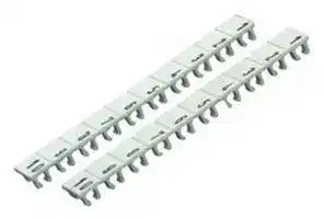
04.841.1250.0
TERMINAL BLOCK MARKER, 2
⚠️ Reference pricing provided. In case of supply shortages, we will connect you with our trusted procurement partners to ensure your project's continuity.
- Manufacturer: WIELAND ELECTRIC
- Product type: Terminal Block Markers
- Legend: 2
- For Use With: DIN Rail Terminal Blocks
- Accessory Type: Terminal Block Marker
| Delivery and price | |
|---|---|
| Units per pack | 500 |
| Price | 14.39 € |
| Current stock | 10+ |
| Lead time | 30 days |
Datasheet

270

**==> picture [300 x 98] intentionally omitted <==**

**----- Start of picture text -----**<br>
Excerpt from<br>our master catalogue [<7]<br>**----- End of picture text -----**<br>


## **PCB terminals** _**wieconwiecon**_

In general, all Wieland components which are obliged to have the A identification are provided with the A mark

## **Pluggable PCB terminals and headers**

**Two part PCB terminals with pin strip headers**

**Modular railmount terminals with integral**

**PCB edge connectors**

**PCB terminals**

**2 tier PCB terminals**

**3 tier PCB terminals**

**4 tier PCB terminals**

**Special terminals**

_**RAST 5**_ **system Termination modules Marker tag/strips**

272

## **CONTENTS**

## _**wiecon**_ **CONTENTS**

|||
|---|---|
||**Pitch 3.50/3.81 mm**<br>• Terminal connector, rising cage clamp version<br>Page 280<br>• Terminal connector, spring clamp version<br>Page 281<br>• Header<br>Page 284<br>**Pitch 5.00/5.08/7.50/7.62 mm**<br>• Terminal connector, rising cage clamp version<br>Page 286<br>• Header with in-line terminal<br>spring clamp version (= inverted socket)<br>Page 295<br>• Terminal connector, spring clamp version<br>Page 294<br>• Terminal connector, soldered version<br>Page 295<br>• Headers<br>Page 297<br>• TOP plug with strain relief<br>Page 320|
||**Pitch 3.50/5.00 mm**screw version<br>Page 316<br>**Pitch 3.50 mm**spring clamp version<br>Page 324|
|**header**|**Pitch 5.00 mm modular railmount terminals with integral header**<br>Page 310|
||**Pitch 3.50 mm**rising cage clamp version<br>Page 328<br>**Pitch 5.00 mm**rising cage clamp version<br>Page 330|
||**Pitch 3.50/3.81 mm**<br>• rising cage clamp version<br>Page 280<br>**Pitch 5.00/5.08 mm**<br>• rising cage clamp version<br>Page 286<br>• spring clamp version<br>Page 292<br>**Pitch 6,35 mm**<br>Page 355<br>**Pitch 7.50/7.62 mm**<br>• rising cage clamp version<br>Page 288<br>• spring clamp version<br>Page 294<br>**Pitch 10.00/10.16 mm**<br>• rising cage clamp version<br>Page 318, 375, 377|
||**Pitch 5.00/5.08 mm**<br>• rising cage clamp version<br>Page 364|
||**Pitch 5.00/5.08 mm**<br>• rising cage clamp version<br>Page 370|
||**Pitch 5.00 mm**<br>• rising cage clamp version<br>Page 373|
||**Pitch 5.08 mm**<br>• Modular terminal<br>Page 378<br>• Disconnect terminal<br>Page 378<br>• Modular fuse terminal<br>Page 379<br>• ASI connector<br>Page 392|
||Page 380<br>Page 386<br>Page 394|


273

## **Pluggable PCB terminals and headers** _**wieconwiecon**_ PCB

**==> picture [561 x 692] intentionally omitted <==**

**----- Start of picture text -----**<br>
Page 298 Page 301 Page 299 Page 299 Page 301 Page 297 Page 300 Page 297 Page 298<br>Pitch 5.00/5.08 7.50/7.62 5.00/5.08 5.00/5.08 7.50/7.62 5.00/5.08 7.50/7.62 5.00/5.08 5.00/5.08<br>Pitch 5.00/5.08 mm 8113 S/W 8313 S/W 8113 S/WOF 8113 S/WF 8313 S/WF 8113 S/G 8313 S/G 8113 S/GOF 8113 S/GF<br>Pitch 7.50/7.62 mm 8213 S/W 8413 S/W 8213 S/WOF 8213 S/WF 8413 S/WF 8213 S/G 8413 S/G 8213 S/GOF 8213 S/GF<br>Pole 2 – 24 2 – 12 2 – 24 2 – 22 2 – 12 2 – 24 2 – 12 2 – 24 2 – 22<br>Page 291<br>2 – 24 • • • •<br>8113 BK 5.00 8113 8113 8113 8113<br>Page 286<br>8113 B 5.00 2 – 24 • • • •<br>8213 B 5.08<br>Page 292<br>8113 BFK 5.00 2 – 24 • • • • •<br>8213 BFK 5.08<br>Page 287<br>2 – 24 • •<br>8213 B/S 5.08 8213 8213<br>Page 288<br>8313 B 7.50 2 – 22 • •<br>8413 B 7.62<br>Page 286<br>8113 B/F 5.00 2 – 12 • •<br>8213 B/F 5.08<br>Page 288<br>8313 B/F 7.50 2 – 24 •<br>8413 B/F 7.62<br>Page 289<br>8113 B/VL 5.00 2 – 24 • • • •<br>8213 B/VL 5.08<br>Page 289<br>8113 B/VR 5.00 2 – 12 • • • •<br>8213 B/VR 5.08<br>Page 290<br>2 – 12 • •<br>8413 B/VL 7.62<br>Page 290<br>2 – 24 • •<br>8413 B/VR 7.62<br>Page 296<br>8113 B/TOP 5.00 2 – 24 • • • •<br>8213 B/TOP 5.08<br>Page 295<br>2 – 24 • • • •<br>8213 BL/G 5.08<br>Page 295<br>• • • •<br>8213 BL/W 5.08<br>274<br>**----- End of picture text -----**<br>


|**_wiecon_**<br>275<br>8213<br>8213<br>8213<br>8213<br>8213<br>8213<br>8213<br>8213<br>8113<br>8213<br>8113<br>8213<br>8113<br>8113<br>8213<br>8113<br>8113<br>8213<br>8213<br>8213<br>8213<br>8213<br>8213<br>8213<br>8213<br>8213<br>~~**7.50/7.62**~~<br>~~**5.00/5.08**~~<br>~~**5.00/5.08**~~<br>~~**5.08**~~<br>~~**5.00/5.08**~~<br>~~**5.00/5.08**~~<br>~~**5.08**~~<br>~~**5.08**~~<br>~~**5.08**~~<br>~~**5.08**~~<br>~~**5.00/5.08**~~<br>~~**5.00/5.08**~~<br>**8313 S/GF**<br>**8113 S/S**<br>**8113 S/S1**<br>**8213 SUFK**<br>**8113 SE/W**<br>**8113 SE/G**<br>**8213 S/**<br>**8213 S/**<br>**8213 S/**<br>**8213 S/**<br>**8113 SEG/W**<br>**8113 SEG/G**<br>**8413 S/GF**<br>**8213 S/S**<br>**8213 S/S1**<br>**8213 SE/W**<br>**8213 SE/G**<br>**DFWW**<br>**DFWWM**<br>**DFLS**<br>**DFLSM**<br>**8213 SEG/W**<br>**8213 SEG/G**<br>2 – 12<br>2 – 24<br>2 – 24<br>2 – 12 (24)<br>2 – 24<br>2 – 24<br>2 – 24<br>2 – 22<br>2 – 24<br>2 – 22<br>2 – 24<br>2 – 24<br>•<br>•<br>•<br>•<br>•<br>•<br>•<br>•<br>•<br>•<br>•<br>•<br>•<br>•<br>•<br>•<br>•<br>•<br>•<br>•<br>•<br>•<br>•<br>•<br>•<br>•<br>•<br>•<br>•<br>•<br>•<br>•<br>•<br>•<br>•<br>•<br>•<br>•<br>•<br>•<br>•<br>•<br>•<br>•<br>•<br>•<br>•<br>•<br>•<br>•<br>•<br>•<br>•<br>•<br>•<br>•<br>•<br>•<br>•<br>•<br>•<br>•<br>•<br>•<br>•<br>•<br>•<br>•<br>•<br>•<br>•<br>•<br>•<br>•<br>•<br>•<br>•<br>Page 300<br>Page 302<br>Page 302<br>Page 293<br>Page<br>Page<br>Page 305<br>Page 305<br>Page 304<br>Page 304<br>303<br>303<br>slot together<br>slot together<br>with nut<br>with nut|**_wiecon_**<br>275<br>8213<br>8213<br>8213<br>8213<br>8213<br>8213<br>8213<br>8213<br>8113<br>8213<br>8113<br>8213<br>8113<br>8113<br>8213<br>8113<br>8113<br>8213<br>8213<br>8213<br>8213<br>8213<br>8213<br>8213<br>8213<br>8213<br>~~**7.50/7.62**~~<br>~~**5.00/5.08**~~<br>~~**5.00/5.08**~~<br>~~**5.08**~~<br>~~**5.00/5.08**~~<br>~~**5.00/5.08**~~<br>~~**5.08**~~<br>~~**5.08**~~<br>~~**5.08**~~<br>~~**5.08**~~<br>~~**5.00/5.08**~~<br>~~**5.00/5.08**~~<br>**8313 S/GF**<br>**8113 S/S**<br>**8113 S/S1**<br>**8213 SUFK**<br>**8113 SE/W**<br>**8113 SE/G**<br>**8213 S/**<br>**8213 S/**<br>**8213 S/**<br>**8213 S/**<br>**8113 SEG/W**<br>**8113 SEG/G**<br>**8413 S/GF**<br>**8213 S/S**<br>**8213 S/S1**<br>**8213 SE/W**<br>**8213 SE/G**<br>**DFWW**<br>**DFWWM**<br>**DFLS**<br>**DFLSM**<br>**8213 SEG/W**<br>**8213 SEG/G**<br>2 – 12<br>2 – 24<br>2 – 24<br>2 – 12 (24)<br>2 – 24<br>2 – 24<br>2 – 24<br>2 – 22<br>2 – 24<br>2 – 22<br>2 – 24<br>2 – 24<br>•<br>•<br>•<br>•<br>•<br>•<br>•<br>•<br>•<br>•<br>•<br>•<br>•<br>•<br>•<br>•<br>•<br>•<br>•<br>•<br>•<br>•<br>•<br>•<br>•<br>•<br>•<br>•<br>•<br>•<br>•<br>•<br>•<br>•<br>•<br>•<br>•<br>•<br>•<br>•<br>•<br>•<br>•<br>•<br>•<br>•<br>•<br>•<br>•<br>•<br>•<br>•<br>•<br>•<br>•<br>•<br>•<br>•<br>•<br>•<br>•<br>•<br>•<br>•<br>•<br>•<br>•<br>•<br>•<br>•<br>•<br>•<br>•<br>•<br>•<br>•<br>•<br>Page 300<br>Page 302<br>Page 302<br>Page 293<br>Page<br>Page<br>Page 305<br>Page 305<br>Page 304<br>Page 304<br>303<br>303<br>slot together<br>slot together<br>with nut<br>with nut|**_wiecon_**<br>275<br>8213<br>8213<br>8213<br>8213<br>8213<br>8213<br>8213<br>8213<br>8113<br>8213<br>8113<br>8213<br>8113<br>8113<br>8213<br>8113<br>8113<br>8213<br>8213<br>8213<br>8213<br>8213<br>8213<br>8213<br>8213<br>8213<br>~~**7.50/7.62**~~<br>~~**5.00/5.08**~~<br>~~**5.00/5.08**~~<br>~~**5.08**~~<br>~~**5.00/5.08**~~<br>~~**5.00/5.08**~~<br>~~**5.08**~~<br>~~**5.08**~~<br>~~**5.08**~~<br>~~**5.08**~~<br>~~**5.00/5.08**~~<br>~~**5.00/5.08**~~<br>**8313 S/GF**<br>**8113 S/S**<br>**8113 S/S1**<br>**8213 SUFK**<br>**8113 SE/W**<br>**8113 SE/G**<br>**8213 S/**<br>**8213 S/**<br>**8213 S/**<br>**8213 S/**<br>**8113 SEG/W**<br>**8113 SEG/G**<br>**8413 S/GF**<br>**8213 S/S**<br>**8213 S/S1**<br>**8213 SE/W**<br>**8213 SE/G**<br>**DFWW**<br>**DFWWM**<br>**DFLS**<br>**DFLSM**<br>**8213 SEG/W**<br>**8213 SEG/G**<br>2 – 12<br>2 – 24<br>2 – 24<br>2 – 12 (24)<br>2 – 24<br>2 – 24<br>2 – 24<br>2 – 22<br>2 – 24<br>2 – 22<br>2 – 24<br>2 – 24<br>•<br>•<br>•<br>•<br>•<br>•<br>•<br>•<br>•<br>•<br>•<br>•<br>•<br>•<br>•<br>•<br>•<br>•<br>•<br>•<br>•<br>•<br>•<br>•<br>•<br>•<br>•<br>•<br>•<br>•<br>•<br>•<br>•<br>•<br>•<br>•<br>•<br>•<br>•<br>•<br>•<br>•<br>•<br>•<br>•<br>•<br>•<br>•<br>•<br>•<br>•<br>•<br>•<br>•<br>•<br>•<br>•<br>•<br>•<br>•<br>•<br>•<br>•<br>•<br>•<br>•<br>•<br>•<br>•<br>•<br>•<br>•<br>•<br>•<br>•<br>•<br>•<br>Page 300<br>Page 302<br>Page 302<br>Page 293<br>Page<br>Page<br>Page 305<br>Page 305<br>Page 304<br>Page 304<br>303<br>303<br>slot together<br>slot together<br>with nut<br>with nut|**_wiecon_**<br>275<br>8213<br>8213<br>8213<br>8213<br>8213<br>8213<br>8213<br>8213<br>8113<br>8213<br>8113<br>8213<br>8113<br>8113<br>8213<br>8113<br>8113<br>8213<br>8213<br>8213<br>8213<br>8213<br>8213<br>8213<br>8213<br>8213<br>~~**7.50/7.62**~~<br>~~**5.00/5.08**~~<br>~~**5.00/5.08**~~<br>~~**5.08**~~<br>~~**5.00/5.08**~~<br>~~**5.00/5.08**~~<br>~~**5.08**~~<br>~~**5.08**~~<br>~~**5.08**~~<br>~~**5.08**~~<br>~~**5.00/5.08**~~<br>~~**5.00/5.08**~~<br>**8313 S/GF**<br>**8113 S/S**<br>**8113 S/S1**<br>**8213 SUFK**<br>**8113 SE/W**<br>**8113 SE/G**<br>**8213 S/**<br>**8213 S/**<br>**8213 S/**<br>**8213 S/**<br>**8113 SEG/W**<br>**8113 SEG/G**<br>**8413 S/GF**<br>**8213 S/S**<br>**8213 S/S1**<br>**8213 SE/W**<br>**8213 SE/G**<br>**DFWW**<br>**DFWWM**<br>**DFLS**<br>**DFLSM**<br>**8213 SEG/W**<br>**8213 SEG/G**<br>2 – 12<br>2 – 24<br>2 – 24<br>2 – 12 (24)<br>2 – 24<br>2 – 24<br>2 – 24<br>2 – 22<br>2 – 24<br>2 – 22<br>2 – 24<br>2 – 24<br>•<br>•<br>•<br>•<br>•<br>•<br>•<br>•<br>•<br>•<br>•<br>•<br>•<br>•<br>•<br>•<br>•<br>•<br>•<br>•<br>•<br>•<br>•<br>•<br>•<br>•<br>•<br>•<br>•<br>•<br>•<br>•<br>•<br>•<br>•<br>•<br>•<br>•<br>•<br>•<br>•<br>•<br>•<br>•<br>•<br>•<br>•<br>•<br>•<br>•<br>•<br>•<br>•<br>•<br>•<br>•<br>•<br>•<br>•<br>•<br>•<br>•<br>•<br>•<br>•<br>•<br>•<br>•<br>•<br>•<br>•<br>•<br>•<br>•<br>•<br>•<br>•<br>Page 300<br>Page 302<br>Page 302<br>Page 293<br>Page<br>Page<br>Page 305<br>Page 305<br>Page 304<br>Page 304<br>303<br>303<br>slot together<br>slot together<br>with nut<br>with nut|**_wiecon_**<br>275<br>8213<br>8213<br>8213<br>8213<br>8213<br>8213<br>8213<br>8213<br>8113<br>8213<br>8113<br>8213<br>8113<br>8113<br>8213<br>8113<br>8113<br>8213<br>8213<br>8213<br>8213<br>8213<br>8213<br>8213<br>8213<br>8213<br>~~**7.50/7.62**~~<br>~~**5.00/5.08**~~<br>~~**5.00/5.08**~~<br>~~**5.08**~~<br>~~**5.00/5.08**~~<br>~~**5.00/5.08**~~<br>~~**5.08**~~<br>~~**5.08**~~<br>~~**5.08**~~<br>~~**5.08**~~<br>~~**5.00/5.08**~~<br>~~**5.00/5.08**~~<br>**8313 S/GF**<br>**8113 S/S**<br>**8113 S/S1**<br>**8213 SUFK**<br>**8113 SE/W**<br>**8113 SE/G**<br>**8213 S/**<br>**8213 S/**<br>**8213 S/**<br>**8213 S/**<br>**8113 SEG/W**<br>**8113 SEG/G**<br>**8413 S/GF**<br>**8213 S/S**<br>**8213 S/S1**<br>**8213 SE/W**<br>**8213 SE/G**<br>**DFWW**<br>**DFWWM**<br>**DFLS**<br>**DFLSM**<br>**8213 SEG/W**<br>**8213 SEG/G**<br>2 – 12<br>2 – 24<br>2 – 24<br>2 – 12 (24)<br>2 – 24<br>2 – 24<br>2 – 24<br>2 – 22<br>2 – 24<br>2 – 22<br>2 – 24<br>2 – 24<br>•<br>•<br>•<br>•<br>•<br>•<br>•<br>•<br>•<br>•<br>•<br>•<br>•<br>•<br>•<br>•<br>•<br>•<br>•<br>•<br>•<br>•<br>•<br>•<br>•<br>•<br>•<br>•<br>•<br>•<br>•<br>•<br>•<br>•<br>•<br>•<br>•<br>•<br>•<br>•<br>•<br>•<br>•<br>•<br>•<br>•<br>•<br>•<br>•<br>•<br>•<br>•<br>•<br>•<br>•<br>•<br>•<br>•<br>•<br>•<br>•<br>•<br>•<br>•<br>•<br>•<br>•<br>•<br>•<br>•<br>•<br>•<br>•<br>•<br>•<br>•<br>•<br>Page 300<br>Page 302<br>Page 302<br>Page 293<br>Page<br>Page<br>Page 305<br>Page 305<br>Page 304<br>Page 304<br>303<br>303<br>slot together<br>slot together<br>with nut<br>with nut|**_wiecon_**<br>275<br>8213<br>8213<br>8213<br>8213<br>8213<br>8213<br>8213<br>8213<br>8113<br>8213<br>8113<br>8213<br>8113<br>8113<br>8213<br>8113<br>8113<br>8213<br>8213<br>8213<br>8213<br>8213<br>8213<br>8213<br>8213<br>8213<br>~~**7.50/7.62**~~<br>~~**5.00/5.08**~~<br>~~**5.00/5.08**~~<br>~~**5.08**~~<br>~~**5.00/5.08**~~<br>~~**5.00/5.08**~~<br>~~**5.08**~~<br>~~**5.08**~~<br>~~**5.08**~~<br>~~**5.08**~~<br>~~**5.00/5.08**~~<br>~~**5.00/5.08**~~<br>**8313 S/GF**<br>**8113 S/S**<br>**8113 S/S1**<br>**8213 SUFK**<br>**8113 SE/W**<br>**8113 SE/G**<br>**8213 S/**<br>**8213 S/**<br>**8213 S/**<br>**8213 S/**<br>**8113 SEG/W**<br>**8113 SEG/G**<br>**8413 S/GF**<br>**8213 S/S**<br>**8213 S/S1**<br>**8213 SE/W**<br>**8213 SE/G**<br>**DFWW**<br>**DFWWM**<br>**DFLS**<br>**DFLSM**<br>**8213 SEG/W**<br>**8213 SEG/G**<br>2 – 12<br>2 – 24<br>2 – 24<br>2 – 12 (24)<br>2 – 24<br>2 – 24<br>2 – 24<br>2 – 22<br>2 – 24<br>2 – 22<br>2 – 24<br>2 – 24<br>•<br>•<br>•<br>•<br>•<br>•<br>•<br>•<br>•<br>•<br>•<br>•<br>•<br>•<br>•<br>•<br>•<br>•<br>•<br>•<br>•<br>•<br>•<br>•<br>•<br>•<br>•<br>•<br>•<br>•<br>•<br>•<br>•<br>•<br>•<br>•<br>•<br>•<br>•<br>•<br>•<br>•<br>•<br>•<br>•<br>•<br>•<br>•<br>•<br>•<br>•<br>•<br>•<br>•<br>•<br>•<br>•<br>•<br>•<br>•<br>•<br>•<br>•<br>•<br>•<br>•<br>•<br>•<br>•<br>•<br>•<br>•<br>•<br>•<br>•<br>•<br>•<br>Page 300<br>Page 302<br>Page 302<br>Page 293<br>Page<br>Page<br>Page 305<br>Page 305<br>Page 304<br>Page 304<br>303<br>303<br>slot together<br>slot together<br>with nut<br>with nut|**_wiecon_**<br>275<br>8213<br>8213<br>8213<br>8213<br>8213<br>8213<br>8213<br>8213<br>8113<br>8213<br>8113<br>8213<br>8113<br>8113<br>8213<br>8113<br>8113<br>8213<br>8213<br>8213<br>8213<br>8213<br>8213<br>8213<br>8213<br>8213<br>~~**7.50/7.62**~~<br>~~**5.00/5.08**~~<br>~~**5.00/5.08**~~<br>~~**5.08**~~<br>~~**5.00/5.08**~~<br>~~**5.00/5.08**~~<br>~~**5.08**~~<br>~~**5.08**~~<br>~~**5.08**~~<br>~~**5.08**~~<br>~~**5.00/5.08**~~<br>~~**5.00/5.08**~~<br>**8313 S/GF**<br>**8113 S/S**<br>**8113 S/S1**<br>**8213 SUFK**<br>**8113 SE/W**<br>**8113 SE/G**<br>**8213 S/**<br>**8213 S/**<br>**8213 S/**<br>**8213 S/**<br>**8113 SEG/W**<br>**8113 SEG/G**<br>**8413 S/GF**<br>**8213 S/S**<br>**8213 S/S1**<br>**8213 SE/W**<br>**8213 SE/G**<br>**DFWW**<br>**DFWWM**<br>**DFLS**<br>**DFLSM**<br>**8213 SEG/W**<br>**8213 SEG/G**<br>2 – 12<br>2 – 24<br>2 – 24<br>2 – 12 (24)<br>2 – 24<br>2 – 24<br>2 – 24<br>2 – 22<br>2 – 24<br>2 – 22<br>2 – 24<br>2 – 24<br>•<br>•<br>•<br>•<br>•<br>•<br>•<br>•<br>•<br>•<br>•<br>•<br>•<br>•<br>•<br>•<br>•<br>•<br>•<br>•<br>•<br>•<br>•<br>•<br>•<br>•<br>•<br>•<br>•<br>•<br>•<br>•<br>•<br>•<br>•<br>•<br>•<br>•<br>•<br>•<br>•<br>•<br>•<br>•<br>•<br>•<br>•<br>•<br>•<br>•<br>•<br>•<br>•<br>•<br>•<br>•<br>•<br>•<br>•<br>•<br>•<br>•<br>•<br>•<br>•<br>•<br>•<br>•<br>•<br>•<br>•<br>•<br>•<br>•<br>•<br>•<br>•<br>Page 300<br>Page 302<br>Page 302<br>Page 293<br>Page<br>Page<br>Page 305<br>Page 305<br>Page 304<br>Page 304<br>303<br>303<br>slot together<br>slot together<br>with nut<br>with nut|**_wiecon_**<br>275<br>8213<br>8213<br>8213<br>8213<br>8213<br>8213<br>8213<br>8213<br>8113<br>8213<br>8113<br>8213<br>8113<br>8113<br>8213<br>8113<br>8113<br>8213<br>8213<br>8213<br>8213<br>8213<br>8213<br>8213<br>8213<br>8213<br>~~**7.50/7.62**~~<br>~~**5.00/5.08**~~<br>~~**5.00/5.08**~~<br>~~**5.08**~~<br>~~**5.00/5.08**~~<br>~~**5.00/5.08**~~<br>~~**5.08**~~<br>~~**5.08**~~<br>~~**5.08**~~<br>~~**5.08**~~<br>~~**5.00/5.08**~~<br>~~**5.00/5.08**~~<br>**8313 S/GF**<br>**8113 S/S**<br>**8113 S/S1**<br>**8213 SUFK**<br>**8113 SE/W**<br>**8113 SE/G**<br>**8213 S/**<br>**8213 S/**<br>**8213 S/**<br>**8213 S/**<br>**8113 SEG/W**<br>**8113 SEG/G**<br>**8413 S/GF**<br>**8213 S/S**<br>**8213 S/S1**<br>**8213 SE/W**<br>**8213 SE/G**<br>**DFWW**<br>**DFWWM**<br>**DFLS**<br>**DFLSM**<br>**8213 SEG/W**<br>**8213 SEG/G**<br>2 – 12<br>2 – 24<br>2 – 24<br>2 – 12 (24)<br>2 – 24<br>2 – 24<br>2 – 24<br>2 – 22<br>2 – 24<br>2 – 22<br>2 – 24<br>2 – 24<br>•<br>•<br>•<br>•<br>•<br>•<br>•<br>•<br>•<br>•<br>•<br>•<br>•<br>•<br>•<br>•<br>•<br>•<br>•<br>•<br>•<br>•<br>•<br>•<br>•<br>•<br>•<br>•<br>•<br>•<br>•<br>•<br>•<br>•<br>•<br>•<br>•<br>•<br>•<br>•<br>•<br>•<br>•<br>•<br>•<br>•<br>•<br>•<br>•<br>•<br>•<br>•<br>•<br>•<br>•<br>•<br>•<br>•<br>•<br>•<br>•<br>•<br>•<br>•<br>•<br>•<br>•<br>•<br>•<br>•<br>•<br>•<br>•<br>•<br>•<br>•<br>•<br>Page 300<br>Page 302<br>Page 302<br>Page 293<br>Page<br>Page<br>Page 305<br>Page 305<br>Page 304<br>Page 304<br>303<br>303<br>slot together<br>slot together<br>with nut<br>with nut|**_wiecon_**<br>275<br>8213<br>8213<br>8213<br>8213<br>8213<br>8213<br>8213<br>8213<br>8113<br>8213<br>8113<br>8213<br>8113<br>8113<br>8213<br>8113<br>8113<br>8213<br>8213<br>8213<br>8213<br>8213<br>8213<br>8213<br>8213<br>8213<br>~~**7.50/7.62**~~<br>~~**5.00/5.08**~~<br>~~**5.00/5.08**~~<br>~~**5.08**~~<br>~~**5.00/5.08**~~<br>~~**5.00/5.08**~~<br>~~**5.08**~~<br>~~**5.08**~~<br>~~**5.08**~~<br>~~**5.08**~~<br>~~**5.00/5.08**~~<br>~~**5.00/5.08**~~<br>**8313 S/GF**<br>**8113 S/S**<br>**8113 S/S1**<br>**8213 SUFK**<br>**8113 SE/W**<br>**8113 SE/G**<br>**8213 S/**<br>**8213 S/**<br>**8213 S/**<br>**8213 S/**<br>**8113 SEG/W**<br>**8113 SEG/G**<br>**8413 S/GF**<br>**8213 S/S**<br>**8213 S/S1**<br>**8213 SE/W**<br>**8213 SE/G**<br>**DFWW**<br>**DFWWM**<br>**DFLS**<br>**DFLSM**<br>**8213 SEG/W**<br>**8213 SEG/G**<br>2 – 12<br>2 – 24<br>2 – 24<br>2 – 12 (24)<br>2 – 24<br>2 – 24<br>2 – 24<br>2 – 22<br>2 – 24<br>2 – 22<br>2 – 24<br>2 – 24<br>•<br>•<br>•<br>•<br>•<br>•<br>•<br>•<br>•<br>•<br>•<br>•<br>•<br>•<br>•<br>•<br>•<br>•<br>•<br>•<br>•<br>•<br>•<br>•<br>•<br>•<br>•<br>•<br>•<br>•<br>•<br>•<br>•<br>•<br>•<br>•<br>•<br>•<br>•<br>•<br>•<br>•<br>•<br>•<br>•<br>•<br>•<br>•<br>•<br>•<br>•<br>•<br>•<br>•<br>•<br>•<br>•<br>•<br>•<br>•<br>•<br>•<br>•<br>•<br>•<br>•<br>•<br>•<br>•<br>•<br>•<br>•<br>•<br>•<br>•<br>•<br>•<br>Page 300<br>Page 302<br>Page 302<br>Page 293<br>Page<br>Page<br>Page 305<br>Page 305<br>Page 304<br>Page 304<br>303<br>303<br>slot together<br>slot together<br>with nut<br>with nut|**_wiecon_**<br>275<br>8213<br>8213<br>8213<br>8213<br>8213<br>8213<br>8213<br>8213<br>8113<br>8213<br>8113<br>8213<br>8113<br>8113<br>8213<br>8113<br>8113<br>8213<br>8213<br>8213<br>8213<br>8213<br>8213<br>8213<br>8213<br>8213<br>~~**7.50/7.62**~~<br>~~**5.00/5.08**~~<br>~~**5.00/5.08**~~<br>~~**5.08**~~<br>~~**5.00/5.08**~~<br>~~**5.00/5.08**~~<br>~~**5.08**~~<br>~~**5.08**~~<br>~~**5.08**~~<br>~~**5.08**~~<br>~~**5.00/5.08**~~<br>~~**5.00/5.08**~~<br>**8313 S/GF**<br>**8113 S/S**<br>**8113 S/S1**<br>**8213 SUFK**<br>**8113 SE/W**<br>**8113 SE/G**<br>**8213 S/**<br>**8213 S/**<br>**8213 S/**<br>**8213 S/**<br>**8113 SEG/W**<br>**8113 SEG/G**<br>**8413 S/GF**<br>**8213 S/S**<br>**8213 S/S1**<br>**8213 SE/W**<br>**8213 SE/G**<br>**DFWW**<br>**DFWWM**<br>**DFLS**<br>**DFLSM**<br>**8213 SEG/W**<br>**8213 SEG/G**<br>2 – 12<br>2 – 24<br>2 – 24<br>2 – 12 (24)<br>2 – 24<br>2 – 24<br>2 – 24<br>2 – 22<br>2 – 24<br>2 – 22<br>2 – 24<br>2 – 24<br>•<br>•<br>•<br>•<br>•<br>•<br>•<br>•<br>•<br>•<br>•<br>•<br>•<br>•<br>•<br>•<br>•<br>•<br>•<br>•<br>•<br>•<br>•<br>•<br>•<br>•<br>•<br>•<br>•<br>•<br>•<br>•<br>•<br>•<br>•<br>•<br>•<br>•<br>•<br>•<br>•<br>•<br>•<br>•<br>•<br>•<br>•<br>•<br>•<br>•<br>•<br>•<br>•<br>•<br>•<br>•<br>•<br>•<br>•<br>•<br>•<br>•<br>•<br>•<br>•<br>•<br>•<br>•<br>•<br>•<br>•<br>•<br>•<br>•<br>•<br>•<br>•<br>Page 300<br>Page 302<br>Page 302<br>Page 293<br>Page<br>Page<br>Page 305<br>Page 305<br>Page 304<br>Page 304<br>303<br>303<br>slot together<br>slot together<br>with nut<br>with nut|**_wiecon_**<br>275<br>8213<br>8213<br>8213<br>8213<br>8213<br>8213<br>8213<br>8213<br>8113<br>8213<br>8113<br>8213<br>8113<br>8113<br>8213<br>8113<br>8113<br>8213<br>8213<br>8213<br>8213<br>8213<br>8213<br>8213<br>8213<br>8213<br>~~**7.50/7.62**~~<br>~~**5.00/5.08**~~<br>~~**5.00/5.08**~~<br>~~**5.08**~~<br>~~**5.00/5.08**~~<br>~~**5.00/5.08**~~<br>~~**5.08**~~<br>~~**5.08**~~<br>~~**5.08**~~<br>~~**5.08**~~<br>~~**5.00/5.08**~~<br>~~**5.00/5.08**~~<br>**8313 S/GF**<br>**8113 S/S**<br>**8113 S/S1**<br>**8213 SUFK**<br>**8113 SE/W**<br>**8113 SE/G**<br>**8213 S/**<br>**8213 S/**<br>**8213 S/**<br>**8213 S/**<br>**8113 SEG/W**<br>**8113 SEG/G**<br>**8413 S/GF**<br>**8213 S/S**<br>**8213 S/S1**<br>**8213 SE/W**<br>**8213 SE/G**<br>**DFWW**<br>**DFWWM**<br>**DFLS**<br>**DFLSM**<br>**8213 SEG/W**<br>**8213 SEG/G**<br>2 – 12<br>2 – 24<br>2 – 24<br>2 – 12 (24)<br>2 – 24<br>2 – 24<br>2 – 24<br>2 – 22<br>2 – 24<br>2 – 22<br>2 – 24<br>2 – 24<br>•<br>•<br>•<br>•<br>•<br>•<br>•<br>•<br>•<br>•<br>•<br>•<br>•<br>•<br>•<br>•<br>•<br>•<br>•<br>•<br>•<br>•<br>•<br>•<br>•<br>•<br>•<br>•<br>•<br>•<br>•<br>•<br>•<br>•<br>•<br>•<br>•<br>•<br>•<br>•<br>•<br>•<br>•<br>•<br>•<br>•<br>•<br>•<br>•<br>•<br>•<br>•<br>•<br>•<br>•<br>•<br>•<br>•<br>•<br>•<br>•<br>•<br>•<br>•<br>•<br>•<br>•<br>•<br>•<br>•<br>•<br>•<br>•<br>•<br>•<br>•<br>•<br>Page 300<br>Page 302<br>Page 302<br>Page 293<br>Page<br>Page<br>Page 305<br>Page 305<br>Page 304<br>Page 304<br>303<br>303<br>slot together<br>slot together<br>with nut<br>with nut|**_wiecon_**<br>275<br>8213<br>8213<br>8213<br>8213<br>8213<br>8213<br>8213<br>8213<br>8113<br>8213<br>8113<br>8213<br>8113<br>8113<br>8213<br>8113<br>8113<br>8213<br>8213<br>8213<br>8213<br>8213<br>8213<br>8213<br>8213<br>8213<br>~~**7.50/7.62**~~<br>~~**5.00/5.08**~~<br>~~**5.00/5.08**~~<br>~~**5.08**~~<br>~~**5.00/5.08**~~<br>~~**5.00/5.08**~~<br>~~**5.08**~~<br>~~**5.08**~~<br>~~**5.08**~~<br>~~**5.08**~~<br>~~**5.00/5.08**~~<br>~~**5.00/5.08**~~<br>**8313 S/GF**<br>**8113 S/S**<br>**8113 S/S1**<br>**8213 SUFK**<br>**8113 SE/W**<br>**8113 SE/G**<br>**8213 S/**<br>**8213 S/**<br>**8213 S/**<br>**8213 S/**<br>**8113 SEG/W**<br>**8113 SEG/G**<br>**8413 S/GF**<br>**8213 S/S**<br>**8213 S/S1**<br>**8213 SE/W**<br>**8213 SE/G**<br>**DFWW**<br>**DFWWM**<br>**DFLS**<br>**DFLSM**<br>**8213 SEG/W**<br>**8213 SEG/G**<br>2 – 12<br>2 – 24<br>2 – 24<br>2 – 12 (24)<br>2 – 24<br>2 – 24<br>2 – 24<br>2 – 22<br>2 – 24<br>2 – 22<br>2 – 24<br>2 – 24<br>•<br>•<br>•<br>•<br>•<br>•<br>•<br>•<br>•<br>•<br>•<br>•<br>•<br>•<br>•<br>•<br>•<br>•<br>•<br>•<br>•<br>•<br>•<br>•<br>•<br>•<br>•<br>•<br>•<br>•<br>•<br>•<br>•<br>•<br>•<br>•<br>•<br>•<br>•<br>•<br>•<br>•<br>•<br>•<br>•<br>•<br>•<br>•<br>•<br>•<br>•<br>•<br>•<br>•<br>•<br>•<br>•<br>•<br>•<br>•<br>•<br>•<br>•<br>•<br>•<br>•<br>•<br>•<br>•<br>•<br>•<br>•<br>•<br>•<br>•<br>•<br>•<br>Page 300<br>Page 302<br>Page 302<br>Page 293<br>Page<br>Page<br>Page 305<br>Page 305<br>Page 304<br>Page 304<br>303<br>303<br>slot together<br>slot together<br>with nut<br>with nut|**_wiecon_**<br>275<br>8213<br>8213<br>8213<br>8213<br>8213<br>8213<br>8213<br>8213<br>8113<br>8213<br>8113<br>8213<br>8113<br>8113<br>8213<br>8113<br>8113<br>8213<br>8213<br>8213<br>8213<br>8213<br>8213<br>8213<br>8213<br>8213<br>~~**7.50/7.62**~~<br>~~**5.00/5.08**~~<br>~~**5.00/5.08**~~<br>~~**5.08**~~<br>~~**5.00/5.08**~~<br>~~**5.00/5.08**~~<br>~~**5.08**~~<br>~~**5.08**~~<br>~~**5.08**~~<br>~~**5.08**~~<br>~~**5.00/5.08**~~<br>~~**5.00/5.08**~~<br>**8313 S/GF**<br>**8113 S/S**<br>**8113 S/S1**<br>**8213 SUFK**<br>**8113 SE/W**<br>**8113 SE/G**<br>**8213 S/**<br>**8213 S/**<br>**8213 S/**<br>**8213 S/**<br>**8113 SEG/W**<br>**8113 SEG/G**<br>**8413 S/GF**<br>**8213 S/S**<br>**8213 S/S1**<br>**8213 SE/W**<br>**8213 SE/G**<br>**DFWW**<br>**DFWWM**<br>**DFLS**<br>**DFLSM**<br>**8213 SEG/W**<br>**8213 SEG/G**<br>2 – 12<br>2 – 24<br>2 – 24<br>2 – 12 (24)<br>2 – 24<br>2 – 24<br>2 – 24<br>2 – 22<br>2 – 24<br>2 – 22<br>2 – 24<br>2 – 24<br>•<br>•<br>•<br>•<br>•<br>•<br>•<br>•<br>•<br>•<br>•<br>•<br>•<br>•<br>•<br>•<br>•<br>•<br>•<br>•<br>•<br>•<br>•<br>•<br>•<br>•<br>•<br>•<br>•<br>•<br>•<br>•<br>•<br>•<br>•<br>•<br>•<br>•<br>•<br>•<br>•<br>•<br>•<br>•<br>•<br>•<br>•<br>•<br>•<br>•<br>•<br>•<br>•<br>•<br>•<br>•<br>•<br>•<br>•<br>•<br>•<br>•<br>•<br>•<br>•<br>•<br>•<br>•<br>•<br>•<br>•<br>•<br>•<br>•<br>•<br>•<br>•<br>Page 300<br>Page 302<br>Page 302<br>Page 293<br>Page<br>Page<br>Page 305<br>Page 305<br>Page 304<br>Page 304<br>303<br>303<br>slot together<br>slot together<br>with nut<br>with nut|**_wiecon_**<br>275<br>8213<br>8213<br>8213<br>8213<br>8213<br>8213<br>8213<br>8213<br>8113<br>8213<br>8113<br>8213<br>8113<br>8113<br>8213<br>8113<br>8113<br>8213<br>8213<br>8213<br>8213<br>8213<br>8213<br>8213<br>8213<br>8213<br>~~**7.50/7.62**~~<br>~~**5.00/5.08**~~<br>~~**5.00/5.08**~~<br>~~**5.08**~~<br>~~**5.00/5.08**~~<br>~~**5.00/5.08**~~<br>~~**5.08**~~<br>~~**5.08**~~<br>~~**5.08**~~<br>~~**5.08**~~<br>~~**5.00/5.08**~~<br>~~**5.00/5.08**~~<br>**8313 S/GF**<br>**8113 S/S**<br>**8113 S/S1**<br>**8213 SUFK**<br>**8113 SE/W**<br>**8113 SE/G**<br>**8213 S/**<br>**8213 S/**<br>**8213 S/**<br>**8213 S/**<br>**8113 SEG/W**<br>**8113 SEG/G**<br>**8413 S/GF**<br>**8213 S/S**<br>**8213 S/S1**<br>**8213 SE/W**<br>**8213 SE/G**<br>**DFWW**<br>**DFWWM**<br>**DFLS**<br>**DFLSM**<br>**8213 SEG/W**<br>**8213 SEG/G**<br>2 – 12<br>2 – 24<br>2 – 24<br>2 – 12 (24)<br>2 – 24<br>2 – 24<br>2 – 24<br>2 – 22<br>2 – 24<br>2 – 22<br>2 – 24<br>2 – 24<br>•<br>•<br>•<br>•<br>•<br>•<br>•<br>•<br>•<br>•<br>•<br>•<br>•<br>•<br>•<br>•<br>•<br>•<br>•<br>•<br>•<br>•<br>•<br>•<br>•<br>•<br>•<br>•<br>•<br>•<br>•<br>•<br>•<br>•<br>•<br>•<br>•<br>•<br>•<br>•<br>•<br>•<br>•<br>•<br>•<br>•<br>•<br>•<br>•<br>•<br>•<br>•<br>•<br>•<br>•<br>•<br>•<br>•<br>•<br>•<br>•<br>•<br>•<br>•<br>•<br>•<br>•<br>•<br>•<br>•<br>•<br>•<br>•<br>•<br>•<br>•<br>•<br>Page 300<br>Page 302<br>Page 302<br>Page 293<br>Page<br>Page<br>Page 305<br>Page 305<br>Page 304<br>Page 304<br>303<br>303<br>slot together<br>slot together<br>with nut<br>with nut|**_wiecon_**<br>275<br>8213<br>8213<br>8213<br>8213<br>8213<br>8213<br>8213<br>8213<br>8113<br>8213<br>8113<br>8213<br>8113<br>8113<br>8213<br>8113<br>8113<br>8213<br>8213<br>8213<br>8213<br>8213<br>8213<br>8213<br>8213<br>8213<br>~~**7.50/7.62**~~<br>~~**5.00/5.08**~~<br>~~**5.00/5.08**~~<br>~~**5.08**~~<br>~~**5.00/5.08**~~<br>~~**5.00/5.08**~~<br>~~**5.08**~~<br>~~**5.08**~~<br>~~**5.08**~~<br>~~**5.08**~~<br>~~**5.00/5.08**~~<br>~~**5.00/5.08**~~<br>**8313 S/GF**<br>**8113 S/S**<br>**8113 S/S1**<br>**8213 SUFK**<br>**8113 SE/W**<br>**8113 SE/G**<br>**8213 S/**<br>**8213 S/**<br>**8213 S/**<br>**8213 S/**<br>**8113 SEG/W**<br>**8113 SEG/G**<br>**8413 S/GF**<br>**8213 S/S**<br>**8213 S/S1**<br>**8213 SE/W**<br>**8213 SE/G**<br>**DFWW**<br>**DFWWM**<br>**DFLS**<br>**DFLSM**<br>**8213 SEG/W**<br>**8213 SEG/G**<br>2 – 12<br>2 – 24<br>2 – 24<br>2 – 12 (24)<br>2 – 24<br>2 – 24<br>2 – 24<br>2 – 22<br>2 – 24<br>2 – 22<br>2 – 24<br>2 – 24<br>•<br>•<br>•<br>•<br>•<br>•<br>•<br>•<br>•<br>•<br>•<br>•<br>•<br>•<br>•<br>•<br>•<br>•<br>•<br>•<br>•<br>•<br>•<br>•<br>•<br>•<br>•<br>•<br>•<br>•<br>•<br>•<br>•<br>•<br>•<br>•<br>•<br>•<br>•<br>•<br>•<br>•<br>•<br>•<br>•<br>•<br>•<br>•<br>•<br>•<br>•<br>•<br>•<br>•<br>•<br>•<br>•<br>•<br>•<br>•<br>•<br>•<br>•<br>•<br>•<br>•<br>•<br>•<br>•<br>•<br>•<br>•<br>•<br>•<br>•<br>•<br>•<br>Page 300<br>Page 302<br>Page 302<br>Page 293<br>Page<br>Page<br>Page 305<br>Page 305<br>Page 304<br>Page 304<br>303<br>303<br>slot together<br>slot together<br>with nut<br>with nut|
|---|---|---|---|---|---|---|---|---|---|---|---|---|---|---|
||~~**750**~~<br>|~~**762**~~<br>|~~**500508**~~<br>|~~**500508**~~<br>|~~**508**~~<br>~~**500**~~<br> <br><br>303|~~**508**~~<br>|~~**00508**~~<br> <br>303|~~**508**~~<br> <br>||||~~**500508**~~<br>|~~**500**~~<br>|~~**508**~~<br>|
|||||||||||~~**508**~~|~~**508**~~||||
||~~**./.**~~<br>**8313 S/GF**<br>**8413 S/GF**||~~**./.**~~<br>**8113 S/S**<br>**8213 S/S**|~~**./.**~~<br>**8113 S/S1**<br>**8213 S/S1**|~~**.**~~<br>~~**.**~~<br>**8213 SUFK**<br>**8113**<br>**8213**|~~**.**~~<br><br>**SE/W**<br>**8**<br>**SE/W**<br>**8**|~~**./.**~~<br>**113 SE/G**<br>**213 SE/G**|~~**.**~~<br>**8213 S/**<br>**DFWW**|~~**.**~~<br>**8213 S/**<br>**DFWWM**|~~**.**~~<br>**8213 S/**<br>**DFLS**|~~**.**~~<br>**8213 S/**<br>**DFLSM**|~~**./.**~~<br>**8113 SEG/W**<br>**8213 SEG/W**|~~**.**~~<br>**8113**<br>**8213**|~~**.**~~<br>**SEG/G**<br>**SEG/G**|
||2 – 12||2 – 24|2 – 24|2 – 12 (24)<br>2 –<br>slot tog|24<br>ether<br>s|2 – 24<br>lot together|2 – 24|2 – 22<br>with nut|2 – 24|2 – 22<br>with nut|2 – 24|2 –|24|
||||8113<br>•|8113<br>•|81<br>|13<br>•|8113<br>•|||||8113<br>•|8<br>|113<br>•|
||||•|•|8213<br>•<br>|•|•|•||•||•||•|
||||•|•|8213<br>•<br>|•|•|•|•|8213<br>•|•|•||•|
||||8213<br>•|8213<br>•|•||8213<br>•|•||•|8213<br>•||8<br>|213<br>•|
||||||||||||||||
||||||8213<br>•||||•||•|•||•|
||•||||||||||||||
||||•|•|8213<br>•<br>|•|•|•|•|8213<br>•|8213<br>•|•||•|
||||•|•|8213<br>•<br>|•|•|•|•|8213<br>•|8213<br>•|•||•|
||||||||||||||||
||||||||||||||||
||||•|•|8213<br>•<br>|•|•|•||•||•||•|
||||•|•|8213<br>•|||||||8213<br>•|8<br>|213<br>•|
||||||8213<br>•||||||||||
||||||||||||||||


## **Pluggable PCB terminals and modular railmount terminals** _**wieconwiecon**_ PCB

**==> picture [561 x 692] intentionally omitted <==**

**----- Start of picture text -----**<br>
Page 310 Page 310 Page 311 Page 312 Page 312 Page 308<br>Pitch 5.00 5.00 7.50 5.00 7.50 5.00<br>Pitch    5.00/7.50 mm<br>2 – 24 2 – 24 2 – 12 2 – 24 2 – 12 2 – 24<br>slot together slot together slot together slot together slot together slot together<br>Page 286 2 – 24 • • •<br>8113 B 5.00<br>Page 288 2 – 12 • •<br>8313 B 7.50<br>Page 289 2 – 24 • • •<br>8113 B/VL 5.00<br>Page 289 2 – 24 • • •<br>8113 B/VR 5.00<br>Page 296 2 – 24 • • •<br>8113 B/TOP 5.00<br>Page 292 2 – 24 • • • • •<br>8113 BFK 5.00<br>276<br>**----- End of picture text -----**<br>


## **Pluggable PCB terminals and headers**

## _**wiecon**_ **Pluggable PCB terminals and headers**

|||~~**Pith**~~||~~**350381**~~<br>Page 284|~~**350381**~~<br>Page 285|~~**350381**~~<br>Page 284|~~**350381**~~<br>Page 285|
|---|---|---|---|---|---|---|---|
||**Pitch    3.81 mm**<br>**Pitch    3.50 mm**<br>Page 280<br>**8513 B**<br>**8813 B**|~~**c**~~||~~**./.**~~<br>**8513 S/W**<br>**8813 S/W**|~~**./.**~~<br>**8513 S/WF**<br>**8813 S/WF**|~~**./.**~~<br>**8513 S/G**<br>**8813 S/G**|~~**./.**~~<br>**8513 S/GF**<br>**8813 S/GF**|
|||||2 – 20|2 – 20|2 – 20|2 – 20|
|||**3.50**<br>**3.81**|2 – 20|•||•||
||Page 280<br>**8513 B/F**<br>**8813 B/F**|**3.50**<br>**3.81**|2 - 20||•||•|
|||||||||
||Page 282<br>**8813 B/VR**|**3.81**|2 - 20|•<br>8813||•<br>8813||
||Page 282<br>**8813 B/VL**|**3.81**|2 - 20|•<br>8813||•<br>8813||
||Page 283<br>**8813 B/VRF**|**3.81**|2 - 20||•<br>8813||•<br>8813|
||Page 283<br>**8813 B/VLF**|**3.81**|2 - 20||•<br>8813||•<br>8813|
||Page 281<br>**8513 BFK**|**3.50**|2 – 20|•<br>8513||•<br>8513||
|||||||||
|||||||||


## **Pluggable PCB terminals and headers**

## **Pluggable PCB terminals and headers** _**wieconwiecon**_ PCB

**Pluggable connection** describes the method used to connect an external conductor to a PCB, via a terminal connector and header

## **System features**

- ❐ plug in system is simple to maintain

- ❐ screw termination by means of rising cage clamp for security

   - ❐ PCB terminals with closed side walls: ensure no miss-connection

   - ❐ PCB terminals with open side walls enable expansion with no effect on the pitch to the circuit board

   - ❐ pitch options: 3.81/5.00/5.08/ 7.50/7.62/10.00/10.16 mm

   - ❐ two tier headers

- ❐ screw connection is easy to operate

- ❐ spring clamp connection for speed

- ❐ comprehensive range means that the direction of insertion/withdrawal and conductor guide methodology can be individually matched to the application

- ❐ simple, clear and secure method of connecting and disconnecting

## **Flange version**

   - ❐ terminal connectors and headers can also incorporate additional fixing elements such as screw flanges which helps prevent them being separated accidentally

   - ❐ secure electrical and mechanical connection even under shock and vibration

- ❐ multiple pole configuration

- ❐ connection of single core and finely stranded conductors up to 1.5 mm[2] and 2.5 mm[2]

- ❐ metric and imperial pitch options The pitch measured in inches can be identified by a pip on the conductor guide funnel

- ❐ clamping with TOP connection

## **Coding**

- ❐ a coding system is available to prevent the connection of non-interchangeable components.  The coding parts can be inserted into special slots in either or both the terminal connector and header

- ❐ coding does not effect number of available poles

- ❐ coding possible with a minimum of 4 poles

## **Marking**

- ❐ clear pole marking which is easy to read enabling easy connection

- ❐ by means of ink jet printing directly onto the terminal connector using indelible ink

- ❐ special marking is possible on request

## **DQS certification for all product areas**

- ❐ Quality standard in accordance with DIN ISO 9001

- ❐ In development, production and installation

**Applications**

- ❐ designed for frequent and ongoing equipment maintenance and system changes as the pluggable terminal connector and PCB header are easily connected and disconnected

- ❐ prefabricated wiring arrangements can be easily interfaced to connect and enable the system

- ❐ Continued control of the quality standard by means of regular internal and external quality audits

- ❐ Compatible with certificates of other countries:

- BSI, Great Britain

- SQS, Switzerland

- Aib-Vincotte, Belgium

- ÖQS, Austria

## **Type range**

- ❐ 2 - 24 pole

- ❐ different variants of terminals and headers allow for horizontal, vertical and angled connection of wiring in relation to the PCB (eg. 35˚)

278

## _**wiecon**_

## **System 8813**

- ❐ mini-PCB terminals 2 to 20 pole

- ❐ terminal and header horizontal or vertical in relation to the PCB

- ❐ total design height: 11 mm, of which only 8 mm is above the PCB

- ❐ in the space saving 3.81 mm pitch

- ❐ conductor size 1.5 mm[2]

- ❐ suitable for coding:

- plug terminal with coding pins

- socket header with coding channels

- ❐ also with locking flange

## **Panel mount header**

- ❐ header can be inserted in the unit wall (see inset)

- ❐ plug in connection through the wall

- ❐ header = bush housing

- ❐ threaded bush for vibration resistant screw connection of flange designs

- ❐ can be screwed to the housing wall

- ❐ connecting wiring inside the housing via termi-point or solder connection

## **Inverted version**

- ❐ solderable terminal as header with straight and angled socket solder pins

- ❐ can be coded using coding parts in special slots

- ❐ the mounting holder enables locking with the header

## **Materials**

## Metal components

- ❐ made from special alloys and/ or special surface treatments for:

- ❐ clamping part and clamping screw: made from nickel plated brass top version: galvanised and chromated steel

- ❐ socket contact: tinned bronze

- ❐ header and solder pins: made from a high quality copper alloy

- ❐ minimum contact resistance

- ❐ high corrosion protection

- ❐ secure, dynamic clamping function

Insulating housing:

- ❐ Polyamide 66/6, used on account of its excellent electrical, chemical and mechanical properties (see _**facts**_ & DATA section)

- ❐ material in accordance with UL 94 V-0

- ❐ colour grey, similar to RAL 7032

❐ glass filled for additional reinforcement (no glass reinforcement in tiertype header and solderable parts)

## **Abbreviations for plastic material markings:**

PA 66/6 = Polyamide 66/6 PC = Polycarbonate PBT = Polybutylenterephthalate

## **Note:**

The conductor size and connecting capacity relate to unprepared conductors without ferrules.

## **Top version**

- ❐ screw connection and conductor feed in line with connection

- ❐ plug with connection in line with conductor

- ❐ very easy to use in restricted installation conditions

- ❐ with and without integral LED

## **Special types**

- ❐ for the control panel: – terminal blocks with integral header – assembles to 5.00 mm-pitch – can be mounted on DIN rail

- ❐ terminals with header for system 8113

- ❐ with vertical socket outlet

- ❐ with horizontal socket outlet

The rated current specified corresponds to the maximum load of PCB terminal with connected conductor with the given conductor size.

The rated voltage is specified in accordance with DIN VDE 0110 Part 1 (IEC 60 664-1) – Insulation coordination for electrical equipment in low voltage installations and refers to the received condition of the PCB terminals.

When fitting PCB terminals to the PCB, the appropriate PCB must be selected and given the relevant dimensions (e.g. as regards the resistance of the PCB to creepage, spacing of the conductors and soldering pads).

In addition, the influences of the environment (level of pollution) to which the equipment is to be exposed are to be taken into account.  The specified rate voltages for the whole module only apply if the PCB and PCB terminal have been matched correctly and carefully.

279

## **Pluggable PCB terminal, rising cage clamp system, pitch 3.50/3.81 mm** _**wieconwiecon**_ PCB

cable size

**1.5 mm[2]**

|Rated cross section:|Rated cross section:|Rated cross section:|Rated cross section:|Rated cross section:||||||||||||||
|---|---|---|---|---|---|---|---|---|---|---|---|---|---|---|---|---|---|
|1.5 mm2||||||||||||||||||
|Rated current:||||||||SS|i<br>Port _|||;<br>123/92|||IR<br>ost|_||
|8 A||||||||||||||||||
|Wire range:<br>0.14 – 1.5 mm2 single core/finely stranded||||||single core/finely stranded||3.81<br>T<br>=||-<br>|<br>55||361<br>cain<br>143<br>|<br>|17s!<br>Le) ed<br>GFL<br>__||||5S<br>-|||
||125 V/2.5 kV/3 – overvoltage category III|||||||||||||||||
||250 V/2.5 kV/2 – overvoltage category II|||||||||||||||||
|*690 V/2.5 kV/1 – overvoltage category I||||||||||||||||||
|* max. 600V for non earthed systems or expected overvoltage<br>≤3 kV for L≥2.00 mm and|||max. 600V for non earthed systems or expected overvoltage<br>2.00 mm and≤2.5 kV for 2.0 mm > L|||max. 600V for non earthed systems or expected overvoltage<br>2.5 kV for 2.0 mm > L≥1.5 mm||eee||6.5<br>M 2<br>~~(i~~||**with screw flange**<br>*<br>qqxncceeees|||6.5<br>M 2<br>~~(_~~—|||
|||||||||**Type 8513 B/...,  8813 B/...**||**Type 8513 B/...,  8813 B/...**||**Type 8513 B/...F,  8813 B/...F**|**Type 8513 B/...F,  8813 B/...F**|**Type 8513 B/...F,  8813 B/...F**||||
|||||||||Connection in line with conductor|Connection in line with conductor|||Connection in line with conductor|Connection in line with conductor|||||
|Rated voltages VDE 0110||||||||||||||||||
|UL Data||||||||No. 30 – 16  AWG||300 V|8 A|No. 30 – 16  AWG|||300 V|300 V|8 A|
|CSA Data||||||||No. 22 – 14  AWG||300 V|5 A|No. 22 – 14  AWG|||300 V|300 V|5 A|
|Approvals||||||||qw||||qw||||||
|||~~Box Qty~~||~~GFL~~|~~G~~|~~T~~|~~Pole~~|~~Part No.~~||~~Part No.~~||~~Part No.~~|||~~Part No.~~|||
||**Pitch 3.50 mm**|**Pitch 3.50 mm**||||||unmarked||marked||unmarked|||marked|||
||||100|17.40|7.00|3.50|2|25.640.3253.0||25.640.0253.0||25.641.3253.0|||25.641.0253.0|||
||||100|20.90|10.50|7.00|3|25.640.3353.0||25.640.0353.0||25.641.3353.0|||25.641.0353.0|||
||||50|24.40|14.00|10.50|4|25.640.3453.0||25.640.0453.0||25.641.3453.0|||25.641.0453.0|||
||||50|27.90|17.50|14.00|5|25.640.3553.0||25.640.0553.0||25.641.3553.0|||25.641.0553.0|||
||||50|31.40|21.00|17.50|6|25.640.3653.0||25.640.0653.0||25.641.3653.0|||25.641.0653.0|||
||||50|34.90|24.50|21.00|7|25.640.3753.0||25.640.0753.0||25.641.3753.0|||25.641.0753.0|||
||||50|38.40|28.00|24.50|8|25.640.3853.0||25.640.0853.0||25.641.3853.0|||25.641.0853.0|||
||||50|41.90|31.50|28.00|9|25.640.3953.0||25.640.0953.0||25.641.3953.0|||25.641.0953.0|||
||||50|45.40|35.00|31.50|10|25.640.4053.0||25.640.1053.0||25.641.4053.0|||25.641.1053.0|||
||||50|48.90|38.50|35.00|11|25.640.4153.0||25.640.1153.0||25.641.4153.0|||25.641.1153.0|||
||||50|52.40|42.00|38.50|12|25.640.4253.0||25.640.1253.0||25.641.4253.0|||25.641.1253.0|||
||||50|55.90|45.50|42.00|13|25.640.4353.0||25.640.1353.0||25.641.4353.0|||25.641.1353.0|||
||||50|59.40|49.00|45.50|14|25.640.4453.0||25.640.1453.0||25.641.4453.0|||25.641.1453.0|||
||||50|62.90|52.50|49.00|15|25.640.4553.0||25.640.1553.0||25.641.4553.0|||25.641.1553.0|||
||||50|66.40|56.00|52.50|16|25.640.4653.0||25.640.1653.0||25.641.4653.0|||25.641.1653.0|||
||**Pitch 3.81 mm**|**Pitch 3.81 mm**||||||unmarked||marked||unmarked|||marked|||
||||100|18.01|8.41|3.81|2|25.620.3253.0||25.620.0253.0||25.621.3253.0|||25.621.0253.0|||
||||100|21.82|12.22|7.62|3|25.620.3353.0||25.620.0353.0||25.621.3353.0|||25.621.0353.0|||
||||50|25.63|16.03|11.43|4|25.620.3453.0||25.620.0453.0||25.621.3453.0|||25.621.0453.0|||
||||50|29.44|19.84|15.24|5|25.620.3553.0||25.620.0553.0||25.621.3553.0|||25.621.0553.0|||
||||50|33.25|23.65|19.05|6|25.620.3653.0||25.620.0653.0||25.621.3653.0|||25.621.0653.0|||
||||50|37.06|27.46|22.86|7|25.620.3753.0||25.620.0753.0||25.621.3753.0|||25.621.0753.0|||
||||50|40.87|31.27|26.67|8|25.620.3853.0||25.620.0853.0||25.621.3853.0|||25.621.0853.0|||
||||50|44.68|35.08|30.48|9|25.620.3953.0||25.620.0953.0||25.621.3953.0|||25.621.0953.0|||
||||50|48.49|38.89|34.29|10|25.620.4053.0||25.620.1053.0||25.621.4053.0|||25.621.1053.0|||
||||50|52.30|42.70|38.10|11|25.620.4153.0||25.620.1153.0||25.621.4153.0|||25.621.1153.0|||
||||50|56.11|46.51|41.91|12|25.620.4253.0||25.620.1253.0||25.621.4253.0|||25.621.1253.0|||
||||50|59.92|50.32|45.72|13|25.620.4353.0||25.620.1353.0||25.621.4353.0|||25.621.1353.0|||
||||50|63.73|54.13|49.53|14|25.620.4453.0||25.620.1453.0||25.621.4453.0|||25.621.1453.0|||
||||50|67.54|57.94|53.34|15|25.620.4553.0||25.620.1553.0||25.621.4553.0|||25.621.1553.0|||
||||50|71.35|61.75|57.15|16|25.620.4653.0||25.620.1653.0||25.621.4653.0|||25.621.1653.0|||


280

## **Pluggable PCB terminals, spring clamp system, pitch 3.50 mm** _**wiecon**_

cable size **1.5 mm[2]**

Rated cross section: 1.5 mm[2] Rated current: 8 A Wire range: 0.14 – 1.5 mm[2] single core/finely stranded 125 V/2.5 kV/3 – overvoltage category III 250 V/2.5 kV/2 – overvoltage category II *690 V/2.5 kV/1 – overvoltage category I

|~~Box Qty~~<br>~~G~~<br>~~T~~<br>~~Pole~~|~~Part No.~~<br>~~Part No.~~|~~Part No.~~<br>~~Part No.~~|
|---|---|---|
|~~Box Qty~~<br>~~G~~<br>~~T~~<br>~~Pole~~<br>**Pitch 3.50 mm**Type 8513 BFK|~~Part No.~~<br>~~Part No.~~<br>unmarked<br>marked|~~Part No.~~<br>~~Part No.~~|
|2<br>3<br>4<br>100<br>100<br>50<br>6.90<br>10.40<br>13.90<br>3.50<br>7.00<br>10.50|25.630.0253.0<br>25.630.0353.0<br>25.630.0453.0<br>25.630.3253.0<br>25.630.3353.0<br>25.630.3453.0||
|5<br>6<br>7<br>50<br>50<br>50<br>17.40<br>20.90<br>24.40<br>14.00<br>17.50<br>21.00|25.630.0553.0<br>25.630.0653.0<br>25.630.0753.0<br>25.630.3553.0<br>25.630.3653.0<br>25.630.3753.0||
|8<br>9<br>10<br>50<br>50<br>50<br>27.90<br>31.40<br>34.90<br>24.50<br>28.00<br>31.50|25.630.0853.0<br>25.630.0953.0<br>25.630.1053.0<br>25.630.3853.0<br>25.630.3953.0<br>25.630.4053.0||
|11<br>12<br>13<br>50<br>50<br>50<br>38.40<br>41.90<br>45.40<br>35.00<br>38.50<br>42.00|25.630.1153.0<br>25.630.1253.0<br>25.630.1353.0<br>25.630.4153.0<br>25.630.4253.0<br>25.630.4353.0||
|14<br>15<br>16<br>50<br>50<br>50<br>48.90<br>52.40<br>55.90<br>45.50<br>49.00<br>52.50|25.630.1453.0<br>25.630.1553.0<br>25.630.1653.0<br>25.630.4453.0<br>25.630.4553.0<br>25.630.4653.0||
|**Pitch 3.50 mm**Type 8513 SUFK||marked<br>unmarked|
|100<br>100<br>50<br>2<br>3<br>4<br>8.40<br>11.90<br>15.40<br>3.50<br>7.00<br>10.50||25.642.3253.0<br>25.642.3353.0<br>25.642.3453.0<br>25.642.0253.0<br>25.642.0353.0<br>25.642.0453.0|
|50<br>50<br>50<br>5<br>6<br>7<br>18.90<br>22.40<br>25.90<br>14.00<br>17.50<br>21.00||25.642.3553.0<br>25.642.3653.0<br>25.642.3753.0<br>25.642.0553.0<br>25.642.0653.0<br>25.642.0753.0|
|50<br>50<br>50<br>8<br>9<br>10<br>29.40<br>32.90<br>36.40<br>24.50<br>28.00<br>31.50||25.642.3853.0<br>25.642.3953.0<br>25.642.4053.0<br>25.642.0853.0<br>25.642.0953.0<br>25.642.1053.0|
|50<br>50<br>11<br>12<br>13<br>39.90<br>43.40<br>46.90<br>35.00<br>38.50<br>42.00||25.642.4153.0<br>25.642.4253.0<br>25.642.4353.0<br>25.642.1153.0<br>25.642.1253.0<br>25.642.1353.0|
|14<br>15<br>16<br>50.40<br>53.90<br>57.40<br>45.50<br>49.00<br>52.50||25.642.4453.0<br>25.642.4553.0<br>25.642.4653.0<br>25.642.1453.0<br>25.642.1553.0<br>25.642.1653.0|
|**5**<br>DIN 5264 A 0.4 x 2.5<br>**Accessories:**|06.502.4300.0||
||||


281

## **Pluggable PCB terminals, rising cage clamp system, Pitch 3.81 mm** _**wieconwiecon**_ PCB

**==> picture [47 x 9] intentionally omitted <==**

**----- Start of picture text -----**<br>
cable size<br>**----- End of picture text -----**<br>


**1.5 mm[2]**

|Rated cross section:|Rated cross section:|Rated cross section:|Rated cross section:|Rated cross section:|||||||||||
|---|---|---|---|---|---|---|---|---|---|---|---|---|---|---|
|1.5 mm2||||||||———oo|Tear||SSS Sars|aBae|||
|Rated current:|||||||||||||||
|8 A|||||||||||||||
|Wire range:||Wire range:|||||||||||||
|0.14 – 1.5 mm2 single core/finely stranded<br>125 V/2.5 kV/3 – overvoltage category III<br>250 V/2.5 kV/2 – overvoltage category II||||||||3.81<br>ot<br>G|52| |<br>uy<br>104||3.81||04||
|*690 V/2.5 kV/1 – overvoltage category I|||||||||||||||
||||||||||M 2||||M 2||
|* max. 600V for non earthed systems or expected overvoltage|||max. 600V for non earthed systems or expected overvoltage|||max. 600V for non earthed systems or expected overvoltage|||||||||
||≤3 kV for L≥2.00 mm and||2.00 mm and≤2.5 kV for 2.0 mm > L|||2.5 kV for 2.0 mm > L≥1.5 mm||**Type 8813 B/... VR**|6.5<br>**Type 8813 B/... VR**<br>[4<br>oo ie||**Type 8813 B/... VL**<br>:|**Type 8813 B/... VL**|6.5<br>[4<br>oo ie||
|||||||||Connection at 90° to conductor|||Connection at 90° to conductor||||
|Rated voltages VDE 0110|||||||||||||||
|UL Data||||||||No. 30 – 16  AWG|300 V|8 A|No. 30 – 16  AWG||300 V|8 A|
|CSA Data||||||||No. 22 – 14  AWG|300 V|5 A|No. 22 – 14  AWG||300 V|5 A|
|Approvals||||||||igqw|||igqw||||
|||~~Box Qty~~||~~GFL~~|~~G~~|~~T~~|~~Pole~~|~~Part No.~~|~~Part No.~~||~~Part No.~~||~~Part No.~~||
||**Pitch 3.81 mm**|**Pitch 3.81 mm**||||||unmarked|marked||unmarked||marked||
||||100|18.01|8.41|3.81|2|25.622.3253.0|25.622.0253.0||25.624.3253.0||25.624.0253.0||
||||100|21.82|12.22|7.62|3|25.622.3353.0|25.622.0353.0||25.624.3353.0||25.624.0353.0||
||||50|25.63|16.03|11.43|4|25.622.3453.0|25.622.0453.0||25.624.3453.0||25.624.0453.0||
||||50|29.44|19.84|15.24|5|25.622.3553.0|25.622.0553.0||25.624.3553.0||25.624.0553.0||
||||50|33.25|23.65|19.05|6|25.622.3653.0|25.622.0653.0||25.624.3653.0||25.624.0653.0||
||||50|37.06|27.46|22.86|7|25.622.3753.0|25.622.0753.0||25.624.3753.0||25.624.0753.0||
||||50|40.87|31.27|26.67|8|25.622.3853.0|25.622.0853.0||25.624.3853.0||25.624.0853.0||
||||50|44.68|35.08|30.48|9|25.622.3953.0|25.622.0953.0||25.624.3953.0||25.624.0953.0||
||||50|48.49|38.89|34.29|10|25.622.4053.0|25.622.1053.0||25.624.4053.0||25.624.1053.0||
||||50|52.30|42.70|38.10|11|25.622.4153.0|25.622.1153.0||25.624.4153.0||25.624.1153.0||
||||50|56.11|46.51|41.91|12|25.622.4253.0|25.622.1253.0||25.624.4253.0||25.624.1253.0||
||||50|59.92|50.32|45.72|13|25.622.4353.0|25.622.1353.0||25.624.4353.0||25.624.1353.0||
||||50|63.73|54.13|49.53|14|25.622.4453.0|25.622.1453.0||25.624.4453.0||25.624.1453.0||
||||50|67.54|57.94|53.34|15|25.622.4553.0|25.622.1553.0||25.624.4553.0||25.624.1553.0||
||||50|71.35|61.75|57.15|16|25.622.4653.0|25.622.1653.0||25.624.4653.0||25.624.1653.0||


282

## _**wiecon**_

||M 2|||M 2|M 2||
|---|---|---|---|---|---|---|
||6.5||||6.5||
|**Type 8813 B/... VR F**<br>**with screw flange**|**Type 8813 B/... VR F**<br>oo|ie|**Type 8813 B/... VL F**<br>**with screw flange**<br>oo|||ie|
|Connection at 90° to conductor|||Connection at 90° to conductor|to conductor|||
|No. 30 – 16  AWG|300 V|8 A|No. 30 – 16  AWG|300 V|300 V|8 A|
|No. 22 – 14  AWG|300 V|5 A|No. 22 – 14  AWG|300 V|300 V|5 A|
|igqw|||igqw||||
|~~Part No.~~|~~Part No.~~||~~Part No.~~|~~Part No.~~|||
|unmarked|marked||unmarked|marked|||
|25.623.3253.0|25.623.0253.0||25.625.3253.0|25.625.0253.0|||
|25.623.3353.0|25.623.0353.0||25.625.3353.0|25.625.0353.0|||
|25.623.3453.0|25.623.0453.0||25.625.3453.0|25.625.0453.0|||
|25.623.3553.0|25.623.0553.0||25.625.3553.0|25.625.0553.0|||
|25.623.3653.0|25.623.0653.0||25.625.3653.0|25.625.0653.0|||
|25.623.3753.0|25.623.0753.0||25.625.3753.0|25.625.0753.0|||
|25.623.3853.0|25.623.0853.0||25.625.3853.0|25.625.0853.0|||
|25.623.3953.0|25.623.0953.0||25.625.3953.0|25.625.0953.0|||
|25.623.4053.0|25.623.1053.0||25.625.4053.0|25.625.1053.0|||
|25.623.4153.0|25.623.1153.0||25.625.4153.0|25.625.1153.0|||
|25.623.4253.0|25.623.1253.0||25.625.4253.0|25.625.1253.0|||
|25.623.4353.0|25.623.1353.0||25.625.4353.0|25.625.1353.0|||
|25.623.4453.0|25.623.1453.0||25.625.4453.0|25.625.1453.0|||
|25.623.4553.0|25.623.1553.0||25.625.4553.0|25.625.1553.0|||
|25.623.4653.0|25.640.1653.0||25.625.4653.0|25.625.1653.0|||


283

## **PCB headers, pitch 3.50/3.81 mm** _**wieconwiecon**_ PCB

cable size **1.5 mm[2]**

**==> picture [177 x 78] intentionally omitted <==**

**----- Start of picture text -----**<br>
Rated current:<br>8 A<br>125 V/2.5 kV/3 – overvoltage category III<br>250 V/2.5 kV/2 – overvoltage category II<br>*690 V/2.5 kV/1 – overvoltage category I<br>Approvals for type 8513 have been applied for<br>**----- End of picture text -----**<br>


|~~Box Qty~~<br>~~GFL~~<br>~~G~~<br>~~T~~<br>~~Pole~~|~~Part No.~~<br>~~Part No.~~|~~Part No.~~<br>~~Part No.~~|
|---|---|---|
|~~Box Qty~~<br>~~GFL~~<br>~~G~~<br>~~T~~<br>~~Pole~~<br>**Pitch 3.50 mm**|~~Part No.~~<br>~~Part No.~~<br>unmarked|~~Part No.~~<br>~~Part No.~~<br>unmarked|
|100<br>100<br>50<br>2<br>3<br>4<br>17.40<br>20.90<br>24.40<br>8.40<br>11.90<br>15.40<br>3.50<br>7.00<br>10.50|25.646.0253.0<br>25.646.0353.0<br>25.646.0453.0|25.647.0253.0<br>25.647.0353.0<br>25.647.0453.0|
|50<br>50<br>50<br>5<br>6<br>7<br>27.90<br>31.40<br>34.90<br>18.90<br>22.40<br>25.90<br>14.00<br>17.50<br>21.00|25.646.0553.0<br>25.646.0653.0<br>25.646.0753.0|25.647.0553.0<br>25.647.0653.0<br>25.647.0753.0|
|50<br>50<br>50<br>8<br>9<br>10<br>38.40<br>41.90<br>45.40<br>29.40<br>32.90<br>36.40<br>24.50<br>28.00<br>31.50|25.646.0853.0<br>25.646.0953.0<br>25.646.1053.0|25.647.0853.0<br>25.647.0953.0<br>25.647.1053.0|
|50<br>50<br>50<br>11<br>12<br>13<br>48.90<br>52.40<br>55.90<br>39.90<br>43.40<br>46.90<br>35.00<br>38.50<br>42.00|25.646.1153.0<br>25.646.1253.0<br>25.646.1353.0|25.647.1153.0<br>25.647.1253.0<br>25.647.1353.0|
|50<br>50<br>50<br>14<br>15<br>16<br>59.40<br>62.90<br>66.40<br>50.40<br>53.90<br>57.40<br>45.50<br>49.00<br>52.50|25.646.1453.0<br>25.646.1553.0<br>25.646.1653.0|25.647.1453.0<br>25.647.1553.0<br>25.647.1653.0|
|**Pitch 3.81 mm**|unmarked|unmarked|
|100<br>100<br>50<br>2<br>3<br>4<br>18.01<br>21.82<br>25.63<br>9.01<br>12.82<br>16.63<br>3.81<br>7.62<br>11.43|25.626.0253.0<br>25.626.0353.0<br>25.626.0453.0|25.627.0253.0<br>25.627.0353.0<br>25.627.0453.0|
|50<br>50<br>50<br>5<br>6<br>7<br>29.44<br>33.25<br>37.06<br>20.44<br>24.25<br>28.06<br>15.24<br>19.05<br>22.86|25.626.0553.0<br>25.626.0653.0<br>25.626.0753.0|25.627.0553.0<br>25.627.0653.0<br>25.627.0753.0|
|50<br>50<br>50<br>8<br>9<br>10<br>40.87<br>44.68<br>48.49<br>31.87<br>35.68<br>39.49<br>26.67<br>30.48<br>34.29|25.626.0853.0<br>25.626.0953.0<br>25.626.1053.0|25.627.0853.0<br>25.627.0953.0<br>25.627.1053.0|
|50<br>50<br>50<br>11<br>12<br>13<br>52.30<br>56.11<br>59.92<br>43.30<br>47.11<br>50.92<br>38.10<br>41.91<br>45.72|25.626.1153.0<br>25.626.1253.0<br>25.626.1353.0|25.627.1153.0<br>25.627.1253.0<br>25.627.1353.0|
|50<br>50<br>50<br>14<br>15<br>16<br>63.73<br>67.54<br>71.35<br>54.73<br>58.54<br>62.35<br>49.53<br>53.34<br>57.15|25.626.1453.0<br>25.626.1553.0<br>25.626.1653.0|25.627.1453.0<br>25.627.1553.0<br>25.627.1653.0|
|**Accessories:**|||
|100<br>Coding part<br>(branch)|05.561.0053.0|05.561.0053.0|
|When using coding parts, the coding fins on the terminal<br>connector should be removed|||


284

## _**wiecon**_

Solder pin 0.8 x 0.8 mm Bore hole Ø 1.2 mm

**with screw flange**

Solder pin 0.8 x 0.8 mm Bore hole Ø 1.2 mm

## **with screw flange**

## **Type 8513 S/... GF, 8813 S/... GF**

Connection vertical to PCB

**Type 8513 S/... WF, 8813 S/... WF** Connection horizontal to PCB

## qw

300 V 8 A 300 V 5 A

## qw

|300 V|300 V|8 A|8 A|
|---|---|---|---|
|300 V|300 V|5 A|5 A|


|~~Part No.~~|~~Part No.~~|~~Part No.~~|~~Part No.~~|
|---|---|---|---|
|unmarked||unmarked||
|25.646.3253.0||25.647.3253.0||
|25.646.3353.0||25.647.3353.0||
|25.646.3453.0||25.647.3453.0||
|25.646.3553.0||25.647.3553.0||
|25.646.3653.0||25.647.3653.0||
|25.646.3753.0||25.647.3753.0||
|25.646.3853.0||25.647.3853.0||
|25.646.3953.0||25.647.3953.0||
|25.646.4053.0||25.647.4053.0||
|25.646.4153.0||25.647.4153.0||
|25.646.4253.0||25.647.4253.0||
|25.646.4353.0||25.647.4353.0||
|25.646.4453.0||25.647.4453.0||
|25.646.4553.0||25.647.4553.0||
|25.646.4653.0||25.647.4653.0||
|unmarked||unmarked||
|25.626.3253.0||25.627.3253.0||
|25.626.3353.0||25.627.3353.0||
|25.626.3453.0||25.627.3453.0||
|25.626.3553.0||25.627.3553.0||
|25.626.3653.0||25.627.3653.0||
|25.626.3753.0||25.627.3753.0||
|25.626.3853.0||25.627.3853.0||
|25.626.3953.0||25.627.3953.0||
|25.626.4053.0||25.627.4053.0||
|25.626.4153.0||25.627.4153.0||
|25.626.4253.0||25.627.4253.0||
|25.626.4353.0||25.627.4353.0||
|25.626.4453.0||25.627.4453.0||
|25.626.4553.0||25.627.4553.0||
|25.626.4653.0||25.627.4653.0||
|||||
|05.561.0053.0||05.561.0053.0||


285

cable size

## **Pluggable PCB terminals, rising cage clamp, pitch 5.00/5.08 mm** _**wieconwiecon**_ PCB

**2.5 mm[2]**

Rated cross section: 2.5 mm[2] Rated current: 12 A

Wire range: 0.14 – 2.5 mm[2] single core/finely stranded

250 V/4 kV/3 – overvoltage category III 400 V/4 kV/2 – overvoltage category II 1000 V/4 kV/1 – overvoltage category I

|~~Box Qty~~<br>~~GFL~~<br>~~G~~<br>~~T~~<br>~~Pole~~|~~Part No.~~<br>~~Part No.~~|~~Part No.~~<br>~~Part No.~~|
|---|---|---|
|~~Box Qty~~<br>~~GFL~~<br>~~G~~<br>~~T~~<br>~~Pole~~<br>**Pitch 5.00 mm**<br>Type 8113|~~Part No.~~<br>~~Part No.~~<br>unmarked<br>marked|~~Part No.~~<br>~~Part No.~~<br>unmarked<br>marked|
|100<br>100<br>50<br>2<br>3<br>4<br>20<br>25<br>30<br>10<br>15<br>20<br>5<br>10<br>15|25.320.3253.0<br>25.320.3353.0<br>25.320.3453.0<br>25.320.0253.0<br>25.320.0353.0<br>25.320.0453.0|25.322.3253.0<br>25.322.3353.0<br>25.322.3453.0<br>25.322.0253.0<br>25.322.0353.0<br>25.322.0453.0|
|50<br>50<br>50<br>5<br>6<br>7<br>35<br>40<br>45<br>25<br>30<br>35<br>20<br>25<br>30|25.320.3553.0<br>25.320.3653.0<br>25.320.3753.0<br>25.320.0553.0<br>25.320.0653.0<br>25.320.0753.0|25.322.3553.0<br>25.322.3653.0<br>25.322.3753.0<br>25.322.0553.0<br>25.322.0653.0<br>25.322.0753.0|
|50<br>50<br>50<br>8<br>9<br>10<br>50<br>55<br>60<br>40<br>45<br>50<br>35<br>40<br>45|25.320.3853.0<br>25.320.3953.0<br>25.320.4053.0<br>25.320.0853.0<br>25.320.0953.0<br>25.320.1053.0|25.322.3853.0<br>25.322.3953.0<br>25.322.4053.0<br>25.322.0853.0<br>25.322.0953.0<br>25.322.1053.0|
|50<br>50<br>50<br>11<br>12<br>13<br>65<br>70<br>75<br>55<br>60<br>65<br>50<br>55<br>60|25.320.4153.0<br>25.320.4253.0<br>25.320.4353.0<br>25.320.1153.0<br>25.320.1253.0<br>25.320.1353.0|25.322.4153.0<br>25.322.4253.0<br>25.322.4353.0<br>25.322.1153.0<br>25.322.1253.0<br>25.322.1353.0|
|50<br>50<br>50<br>14<br>15<br>16<br>80<br>85<br>90<br>70<br>75<br>80<br>65<br>70<br>75|25.320.4453.0<br>25.320.4553.0<br>25.320.4653.0<br>25.320.1453.0<br>25.320.1553.0<br>25.320.1653.0|25.322.4453.0<br>25.322.4553.0<br>25.322.4653.0<br>25.322.1453.0<br>25.322.1553.0<br>25.322.1653.0|
|**Pitch 5.08 mm**<br>Type 8213|17 to 24 pole on request<br>unmarked<br>marked|17 to 22 pole on request<br>unmarked<br>marked|
|100<br>100<br>50<br>2<br>3<br>4<br>20.32<br>25.40<br>30.48<br>10.16<br>15.24<br>20.32<br>5.08<br>10.16<br>15.24|25.340.3253.0<br>25.340.3353.0<br>25.340.3453.0<br>25.340.0253.0<br>25.340.0353.0<br>25.340.0453.0|25.323.3253.0<br>25.323.3353.0<br>25.323.3453.0<br>25.323.0253.0<br>25.323.0353.0<br>25.323.0453.0|
|50<br>50<br>50<br>5<br>6<br>7<br>35.56<br>40.64<br>45.72<br>25.40<br>30.48<br>35.56<br>20.32<br>25.40<br>30.48|25.340.3553.0<br>25.340.3653.0<br>25.340.3753.0<br>25.340.0553.0<br>25.340.0653.0<br>25.340.0753.0|25.323.3553.0<br>25.323.3653.0<br>25.323.3753.0<br>25.323.0553.0<br>25.323.0653.0<br>25.323.0753.0|
|50<br>50<br>50<br>8<br>9<br>10<br>50.80<br>55.88<br>60.96<br>40.64<br>45.72<br>50.80<br>35.56<br>40.64<br>45.72|25.340.3853.0<br>25.340.3953.0<br>25.340.4053.0<br>25.340.0853.0<br>25.340.0953.0<br>25.340.1053.0|25.323.3853.0<br>25.323.3953.0<br>25.323.4053.0<br>25.323.0853.0<br>25.323.0953.0<br>25.323.1053.0|
|50<br>50<br>50<br>11<br>12<br>13<br>66.04<br>71.12<br>76.20<br>55.88<br>60.96<br>66.04<br>50.80<br>55.88<br>60.96|25.340.4153.0<br>25.340.4253.0<br>25.340.4353.0<br>25.340.1153.0<br>25.340.1253.0<br>25.340.1353.0|25.323.4153.0<br>25.323.4253.0<br>25.323.4353.0<br>25.323.1153.0<br>25.323.1253.0<br>25.323.1353.0|
|50<br>50<br>50<br>14<br>15<br>16<br>81.28<br>86.36<br>91.44<br>71.12<br>76.20<br>81.28<br>66.04<br>71.12<br>76.20|25.340.4453.0<br>25.340.4553.0<br>25.340.4653.0<br>25.340.1453.0<br>25.340.1553.0<br>25.340.1653.0|25.323.4453.0<br>25.323.4553.0<br>25.323.4653.0<br>25.323.1453.0<br>25.323.1553.0<br>25.323.1653.0|
|**Accessories:**||17 to 22 pole on request|
|100<br>Coding part<br>(branch)|05.561.9153.0|05.561.9153.0|
||||


286

## _**wiecon**_

Rated cross section: 2.5 mm[2]

Rated current: 12 A based on ambient temperature of 20 °C, rated cross-section and max. number of poles

Wire range: 0.5 – 2.5 mm[2] single core/finely stranded

250 V/4 kV/3 – overvoltage category III 400 V/4 kV/2 – overvoltage category II 400 V/4 kV/1 – overvoltage category I

G T Loe"| 5,08 w 15,4 M 2,5 8 ~~Te~~ a

**==> picture [76 x 10] intentionally omitted <==**

**----- Start of picture text -----**<br>
Type 8213 B/...S<br>**----- End of picture text -----**<br>


Rated voltages VDE 0110/1.89 UL Data CSA Data Approvals

**==> picture [344 x 198] intentionally omitted <==**

**----- Start of picture text -----**<br>
||||||||
|---|---|---|---|---|---|---|
|Data|No. 28 –|12  AWG|300 V|10 A|
|CSA Data|No. 28 –|12  AWG|300 V|10 A|
|Approvals|qw|
|Box Qty|GFL|G|T|Pole|Part No.|Part No.|
|Pitch 5.08 mm|unmarked|
|100|10.16|5.08|2|27.341.3253.0|
|100|15.24|10.16|3|27.341.3353.0|
|50|20.32|15.24|4|27.341.3453.0|
|50|25.40|20.32|5|27.341.3553.0|
|50|30.48|25.40|6|27.341.3653.0|
|50|35.56|30.48|7|27.341.3753.0|
|50|40.64|35.56|8|27.341.3853.0|
|50|45.72|40.64|9|27.341.3953.0|
|50|50.80|45.72|10|27.341.4053.0|
|50|55.88|50.80|11|27.341.4153.0|
|50|60.96|55.88|12|27.341.4253.0|
|50|66.04|60.96|13|27.341.4353.0|
|50|71.12|66.04|14|27.341.4453.0|
|50|76.20|71.12|15|27.341.4553.0|
|50|81.28|76.20|16|27.341.4653.0|
|17 to 24 pole on request|

**----- End of picture text -----**<br>


Coding available upon request

287

## **Pluggable PCB terminals, rising cage clamp system, Pitch 7.50/7.62 mm** _**wieconwiecon**_ PCB

cable size

**2.5 mm[2]**

Rated cross section: 2.5 mm[2] Rated current: 12 A

Wire range: 0.14 – 2.5 mm[2] single core/finely stranded

400 V/4 kV/3 – overvoltage category III 690 V/4 kV/2 – overvoltage category II 1000 V/4 kV/1 – overvoltage category I

|~~Box Qty~~<br>~~GFL~~<br>~~G~~<br>~~T~~<br>~~Pole~~|~~Part No.~~<br>~~Part No.~~|~~Part No.~~<br>~~Part No.~~|
|---|---|---|
|~~Box Qty~~<br>~~GFL~~<br>~~G~~<br>~~T~~<br>~~Pole~~<br>**Pitch 7.50 mm**<br>Type 8313|unmarked<br>marked<br>~~Part No.~~<br>~~Part No.~~|unmarked<br>marked<br>~~Part No.~~<br>~~Part No.~~|
|100<br>100<br>50<br>2<br>3<br>4<br>25.54<br>33.04<br>40.54<br>13.00<br>20.50<br>28.00<br>7.50<br>15.00<br>22.50|25.360.3253.0<br>25.360.3353.0<br>25.360.3453.0<br>25.360.0253.0<br>25.360.0353.0<br>25.360.0453.0|25.324.2253.0<br>25.324.2353.0<br>25.324.2453.0<br>25.324.0253.0<br>25.324.0353.0<br>25.324.0453.0|
|50<br>50<br>50<br>5<br>6<br>7<br>48.04<br>55.54<br>63.04<br>35.50<br>43.00<br>50.50<br>30.00<br>37.50<br>45.00|25.360.3553.0<br>25.360.3653.0<br>25.360.3753.0<br>25.360.0553.0<br>25.360.0653.0<br>25.360.0753.0|25.324.2553.0<br>25.324.2653.0<br>25.324.2753.0<br>25.324.0553.0<br>25.324.0653.0<br>25.324.0753.0|
|50<br>50<br>50<br>8<br>9<br>10<br>70.54<br>78.04<br>85.54<br>58.00<br>65.50<br>73.00<br>52.50<br>60.00<br>67.50|25.360.3853.0<br>25.360.3953.0<br>25.360.4053.0<br>25.360.0853.0<br>25.360.0953.0<br>25.360.1053.0|25.324.2853.0<br>25.324.2953.0<br>25.324.3053.0<br>25.324.0853.0<br>25.324.0953.0<br>25.324.1053.0|
|50<br>50<br>11<br>12<br>93.04<br>100.54<br>80.50<br>88.00<br>75.00<br>82.50|25.360.4153.0<br>25.360.4253.0<br>25.360.1153.0<br>25.360.1253.0|25.324.3153.0<br>25.324.3253.0<br>25.324.1153.0<br>25.324.1253.0|
||||
|**Pitch 7.62 mm**<br>Type 8413|unmarked<br>marked|unmarked<br>marked|
|100<br>100<br>50<br>2<br>3<br>4<br>25.66<br>33.28<br>40.90<br>13.12<br>20.74<br>28.36<br>7.62<br>15.24<br>22.86|25.380.3253.0<br>25.380.3353.0<br>25.380.3453.0<br>25.380.0253.0<br>25.380.0353.0<br>25.380.0453.0|25.324.6253.0<br>25.324.6353.0<br>25.324.6453.0<br>25.324.4253.0<br>25.324.4353.0<br>25.324.4453.0|
|50<br>50<br>50<br>5<br>6<br>7<br>48.52<br>56.14<br>63.76<br>35.98<br>43.60<br>51.22<br>30.48<br>38.10<br>45.72|25.380.3553.0<br>25.380.3653.0<br>25.380.3753.0<br>25.380.0553.0<br>25.380.0653.0<br>25.380.0753.0|25.324.6553.0<br>25.324.6653.0<br>25.324.6753.0<br>25.324.4553.0<br>25.324.4653.0<br>25.324.4753.0|
|50<br>50<br>50<br>8<br>9<br>10<br>71.38<br>79.00<br>86.62<br>58.84<br>66.46<br>74.08<br>53.34<br>60.96<br>68.58|25.380.3853.0<br>25.380.3953.0<br>25.380.4053.0<br>25.380.0853.0<br>25.380.0953.0<br>25.380.1053.0|25.324.6853.0<br>25.324.6953.0<br>25.324.7053.0<br>25.324.4853.0<br>25.324.4953.0<br>25.324.5053.0|
|50<br>50<br>11<br>12<br>94.24<br>101.86<br>81.70<br>89.32<br>76.20<br>83.82|25.380.4153.0<br>25.380.4253.0<br>25.380.1153.0<br>25.380.1253.0|25.324.7153.0<br>25.324.7253.0<br>25.324.5153.0<br>25.324.5253.0|
||||
|**Accessories:**|||
|100<br>Coding part<br>(branch)|05.561.9153.0|05.561.9153.0|
||||


288

## **Pluggable PCB terminals, rising cage clamp system, Pitch 5.00/5.08 mm** _**wiecon**_

cable size

**2.5 mm[2]**

Rated cross section: 2.5 mm[2] Rated current: 12 A Wire range: 0.14 – 2.5 mm[2] single core/finely stranded 250 V/4 kV/3 – overvoltage category III 400 V/4 kV/2 – overvoltage category II 1000 V/4 kV/1 – overvoltage category I

M 3 M 3 6 6 ~~ja i~~ **Type 8113 B/... VR, 8213 B/... VR Type 8113 B/... VL, 8213 B/... VL** Connection 90° to conductor Connection 90° to conductor No. 22 – 12  AWG 300 V 15 A No. 22 – 12  AWG 300 V 15 A No. 22 – 12  AWG 300 V 15 A No. 22 – 12  AWG 300 V 15 A üiqwd üiqwd

|~~Box Qty~~<br>~~G~~<br>~~T~~<br>~~Pole~~|~~Part No.~~<br>~~Part No.~~|~~Part No.~~<br>~~Part No.~~|
|---|---|---|
|~~Box Qty~~<br>~~G~~<br>~~T~~<br>~~Pole~~<br>**Pitch 5.00 mm**<br>Type 8113|~~Part No.~~<br>~~Part No.~~<br>unmarked<br>marked|~~Part No.~~<br>~~Part No.~~<br>unmarked<br>marked|
|100<br>100<br>50<br>2<br>3<br>4<br>10<br>15<br>20<br>5<br>10<br>15|25.325.3253.0<br>25.325.3353.0<br>25.325.3453.0<br>25.325.0253.0<br>25.325.0353.0<br>25.325.0453.0|25.326.3253.0<br>25.326.3353.0<br>25.326.3453.0<br>25.326.0253.0<br>25.326.0353.0<br>25.326.0453.0|
|50<br>50<br>50<br>5<br>6<br>7<br>25<br>30<br>35<br>20<br>25<br>30|25.325.3553.0<br>25.325.3653.0<br>25.325.3753.0<br>25.325.0553.0<br>25.325.0653.0<br>25.325.0753.0|25.326.3553.0<br>25.326.3653.0<br>25.326.3753.0<br>25.326.0553.0<br>25.326.0653.0<br>25.326.0753.0|
|50<br>50<br>50<br>8<br>9<br>10<br>40<br>45<br>50<br>35<br>40<br>45|25.325.3853.0<br>25.325.3953.0<br>25.325.4053.0<br>25.325.0853.0<br>25.325.0953.0<br>25.325.1053.0|25.326.3853.0<br>25.326.3953.0<br>25.326.4053.0<br>25.326.0853.0<br>25.326.0953.0<br>25.326.1053.0|
|50<br>50<br>50<br>11<br>12<br>13<br>55<br>60<br>65<br>50<br>55<br>60|25.325.4153.0<br>25.325.4253.0<br>25.325.4353.0<br>25.325.1153.0<br>25.325.1253.0<br>25.325.1353.0|25.326.4153.0<br>25.326.4253.0<br>25.326.4353.0<br>25.326.1153.0<br>25.326.1253.0<br>25.326.1353.0|
|50<br>50<br>50<br>14<br>15<br>16<br>70<br>75<br>80<br>65<br>70<br>75|25.325.4453.0<br>25.325.4553.0<br>25.325.4653.0<br>25.325.1453.0<br>25.325.1553.0<br>25.325.1653.0|25.326.4453.0<br>25.326.4553.0<br>25.326.4653.0<br>25.326.1453.0<br>25.326.1553.0<br>25.326.1653.0|
|17 to 24 pole on request<br>**Pitch 5.08 mm**<br>Type 8213|unmarked<br>marked|unmarked<br>marked|
|100<br>100<br>50<br>2<br>3<br>4<br>10.16<br>15.24<br>20.32<br>5.08<br>10.16<br>15.24|25.345.3253.0<br>25.345.3353.0<br>25.345.3453.0<br>25.345.0253.0<br>25.345.0353.0<br>25.345.0453.0|25.346.3253.0<br>25.346.3353.0<br>25.346.3453.0<br>25.346.0253.0<br>25.346.0353.0<br>25.346.0453.0|
|50<br>50<br>50<br>5<br>6<br>7<br>25.40<br>30.48<br>35.56<br>20.32<br>25.40<br>30.48|25.345.3553.0<br>25.345.3653.0<br>25.345.3753.0<br>25.345.0553.0<br>25.345.0653.0<br>25.345.0753.0|25.346.3553.0<br>25.346.3653.0<br>25.346.3753.0<br>25.346.0553.0<br>25.346.0653.0<br>25.346.0753.0|
|50<br>50<br>50<br>8<br>9<br>10<br>40.64<br>45.72<br>50.80<br>35.56<br>40.64<br>45.72|25.345.3853.0<br>25.345.3953.0<br>25.345.4053.0<br>25.345.0853.0<br>25.345.0953.0<br>25.345.1053.0|25.346.3853.0<br>25.346.3953.0<br>25.346.4053.0<br>25.346.0853.0<br>25.346.0953.0<br>25.346.1053.0|
|50<br>50<br>50<br>11<br>12<br>13<br>55.88<br>60.96<br>66.04<br>50.80<br>55.88<br>60.96|25.345.4153.0<br>25.345.4253.0<br>25.345.4353.0<br>25.345.1153.0<br>25.345.1253.0<br>25.345.1353.0|25.346.4153.0<br>25.346.4253.0<br>25.346.4353.0<br>25.346.1153.0<br>25.346.1253.0<br>25.346.1353.0|
|50<br>50<br>50<br>14<br>15<br>16<br>71.12<br>76.20<br>81.28<br>66.04<br>71.12<br>76.20|25.345.4453.0<br>25.345.4553.0<br>25.345.4653.0<br>25.345.1453.0<br>25.345.1553.0<br>25.345.1653.0|25.346.4453.0<br>25.346.4553.0<br>25.346.4653.0<br>25.346.1453.0<br>25.346.1553.0<br>25.346.1653.0|
|17 to 24 pole on request<br>**Accessories:**|||
|100<br>Coding part<br>(branch)|05.561.9153.0|05.561.9153.0|
||||


289

## **Pluggable PCB terminals, rising cage clamp system, pitch 7.62 mm** _**wieconwiecon**_ PCB

cable size

**2.5 mm[2]**

Rated cross section: 2.5 mm[2] Rated current: 12 A Wire range: 0.14 – 2.5 mm[2] single core/finely stranded 400 V/4 kV/3 – overvoltage category III 690 V/4 kV/2 – overvoltage category II 1000 V/4 kV/1 – overvoltage category I

|~~Box Qty~~<br>~~G~~<br>~~T~~<br>~~Pole~~|~~Part No.~~<br>~~Part No.~~|~~Part No.~~<br>~~Part No.~~|
|---|---|---|
|~~Box Qty~~<br>~~G~~<br>~~T~~<br>~~Pole~~|~~Part No.~~<br>~~Part No.~~|~~Part No.~~<br>~~Part No.~~|
||||
||||
||||
||||
||||
|**Pitch 7.62 mm**<br>Type 8413|unmarked<br>marked|unmarked<br>marked|
|100<br>100<br>50<br>2<br>3<br>4<br>13.12<br>20.74<br>28.36<br>7.62<br>15.24<br>22.86|25.385.2253.0<br>25.385.2353.0<br>25.385.2453.0<br>25.385.0253.0<br>25.385.0353.0<br>25.385.0453.0|25.386.2253.0<br>25.386.2353.0<br>25.386.2453.0<br>25.386.0253.0<br>25.386.0353.0<br>25.386.0453.0|
|50<br>50<br>50<br>5<br>6<br>7<br>35.98<br>43.60<br>51.22<br>30.48<br>38.10<br>45.72|25.385.2553.0<br>25.385.2653.0<br>25.385.2753.0<br>25.385.0553.0<br>25.385.0653.0<br>25.385.0753.0|25.386.2553.0<br>25.386.2653.0<br>25.386.2753.0<br>25.386.0553.0<br>25.386.0653.0<br>25.386.0753.0|
|50<br>50<br>50<br>8<br>9<br>10<br>58.84<br>66.46<br>74.08<br>53.34<br>60.96<br>68.58|25.385.2853.0<br>25.385.2953.0<br>25.385.3053.0<br>25.385.0853.0<br>25.385.0953.0<br>25.385.1053.0|25.386.2853.0<br>25.386.2953.0<br>25.386.3053.0<br>25.386.0853.0<br>25.386.0953.0<br>25.386.1053.0|
|50<br>50<br>11<br>12<br>81.70<br>89.32<br>76.20<br>83.82|25.385.3153.0<br>25.385.3253.0<br>25.385.1153.0<br>25.385.1253.0|25.386.3153.0<br>25.386.3253.0<br>25.386.1153.0<br>25.386.1253.0|
||||
|**Accessories:**|||
|100<br>Coding part<br>(branch)|05.561.9153.0|05.561.9153.0|
||||


290

## _**wiecon**_ **Crimp connection**

Rated cross section: 2.5 mm[2]

Rated current: 10 A when using a 1.0 mm[2] Leiter 12 A when using a 2.5 mm[2] Leiter

Contact for wire range: 0.5 – 1.0 mm[2] finely stranded (Diameter of insulation 1.4 – 2.3 mm)

Wire range: 1.5 – 2.5 mm[2] finely stranded (Diameter of insulation 1.4 – 3.1 mm)

250 V/4 kV/3 – overvoltage category III 400 V/4 kV/2 – overvoltage category II 1000 V/4 kV/1 – overvoltage category I

**==> picture [170 x 97] intentionally omitted <==**

**----- Start of picture text -----**<br>
—<br>4<br>y e<br>Type 8113 BK<br>**----- End of picture text -----**<br>


Rated voltages VDE 0110 UL Data CSA Data Approvals

## w

||||~~Box Qty~~|~~G~~|~~T~~||~~Pole~~|~~Part No.~~|~~Part No.~~|~~Part No.~~|~~Part No.~~|
|---|---|---|---|---|---|---|---|---|---|---|---|
|**Pitch 5.00 mm**|**Pitch 5.00 mm**|**Pitch 5.00 mm**||||||unmarked|marked|||
||||100|10||5|2|01.060.3253.0|01.060.0253.0|||
||||100|15||10|3|01.060.3353.0|01.060.0353.0|||
||||50|20||15|4|01.060.3453.0|01.060.0453.0|||
||||50|25||20|5|01.060.3553.0|01.060.0553.0|||
||||50|30||25|6|01.060.3653.0|01.060.0653.0|||
||||50|35||30|7|01.060.3753.0|01.060.0753.0|||
||||50|40||35|8|01.060.3853.0|01.060.0853.0|||
||||50|45||40|9|01.060.3953.0|01.060.0953.0|||
||||50|50||45|10|01.060.4053.0|01.060.1053.0|||
||||50|55||50|11|01.060.4153.0|01.060.1153.0|||
||||50|60||55|12|01.060.4253.0|01.060.1253.0|||
||||50|65||60|13|01.060.4353.0|01.060.1353.0|||
||||50|70||65|14|01.060.4453.0|01.060.1453.0|||
||||50|75||70|15|01.060.4553.0|01.060.1553.0|||
||||50|80||75|16|01.060.4653.0|01.060.1653.0|||
|||||||||17 to 24 pole on request||||


## **Accessories:**

|**Accessories:**||||
|---|---|---|---|
|**Crimp contacts**||||
|Single contacts|500|0.5 – 1.0 mm2|02.125.1629.0|
|Single contacts|500|1.5 – 2.5 mm2|02.125.1729.0|
|Strip|4000|0.5 – 1.0 mm2|02.125.1600.0|
|Strip|3500|1.5 – 2.5 mm2|02.125.1700.0|
|**Crimping tool:**||||
|Crimping tool|||95.101.0800.0|
|Crimp dies|||05.502.2500.0|


291

## **Pluggable PCB terminals – spring clamp system pitch 5.00/5.08 mm** _**wieconwiecon**_ PCB

**==> picture [529 x 266] intentionally omitted <==**

**----- Start of picture text -----**<br>
Rated cross section*:<br>2.5 mm [2]<br>Rated current: ee eed)d = |” sHOD Cea r—=—(|<br>12 A 2,5 a T rr 15,08 - se ae<br>Wire range:<br>0.14 – 2.5 mm [2] single core/finely stranded g 5,08 | | | 2,54<br>GFL |<br>250 V/4 kV/3 – overvoltage category III<br>400 V/4 kV/2 – overvoltage category II<br>1000 V/4 kV/1 – overvoltage category I<br>ae a<br>. : a *. ——— ee ;<br>llne [a] aan ae _ : ;<br>* When using ferrules for wire range 2.5 mm, only ferrules with<br>part number 2.5 mm 05.596.6127.0 should be used. 11 11<br>oo ro<br>Type 8113/8213 BFK Type 8113/8213 BFK .../F<br>Rated voltages VDE 0110<br>UL Data No. 22 – 12  AWG 300 V 12 A No. 22 – 12  AWG 300 V 12 A<br>CSA Data<br>Approvals  q<br>**----- End of picture text -----**<br>


|~~Box Qty~~<br>~~GFL~~<br>~~G~~<br>~~T~~<br>~~Pole~~|~~Part No.~~<br>~~Part No.~~|~~Part No.~~<br>~~Part No.~~|
|---|---|---|
|~~Box Qty~~<br>~~GFL~~<br>~~G~~<br>~~T~~<br>~~Pole~~<br>**Pitch 5.00 mm**|~~Part No.~~<br>~~Part No.~~<br>unmarked<br>marked|~~Part No.~~<br>~~Part No.~~<br>unmarked<br>marked|
|100<br>100<br>50<br>2<br>3<br>4<br>22.54<br>27.54<br>32.54<br>10<br>15<br>20<br>5<br>10<br>15|25.820.3253.0<br>25.820.3353.0<br>25.820.3453.0<br>25.820.0253.0<br>25.820.0353.0<br>25.820.0453.0|25.821.3253.0<br>25.821.3353.0<br>25.821.3453.0<br>25.821.0253.0<br>25.821.0353.0<br>25.821.0453.0|
|50<br>50<br>50<br>5<br>6<br>7<br>37.54<br>42.54<br>47.54<br>25<br>30<br>35<br>20<br>25<br>30|25.820.3553.0<br>25.820.3653.0<br>25.820.3753.0<br>25.820.0553.0<br>25.820.0653.0<br>25.820.0753.0|25.821.3553.0<br>25.821.3653.0<br>25.821.3753.0<br>25.821.0553.0<br>25.821.0653.0<br>25.821.0753.0|
|50<br>50<br>50<br>8<br>9<br>10<br>52.54<br>57.54<br>62.54<br>40<br>45<br>50<br>35<br>40<br>45|25.820.3853.0<br>25.820.3953.0<br>25.820.4053.0<br>25.820.0853.0<br>25.820.0953.0<br>25.820.1053.0|25.821.3853.0<br>25.821.3953.0<br>25.821.4053.0<br>25.821.0853.0<br>25.821.0953.0<br>25.821.1053.0|
|50<br>50<br>50<br>11<br>12<br>13<br>67.54<br>72.54<br>77.54<br>55<br>60<br>65<br>50<br>55<br>60|25.820.4153.0<br>25.820.4253.0<br>25.820.4353.0<br>25.820.1153.0<br>25.820.1253.0<br>25.820.1353.0|25.821.4153.0<br>25.821.4253.0<br>25.821.4353.0<br>25.821.1153.0<br>25.821.1253.0<br>25.821.1353.0|
|50<br>50<br>50<br>14<br>15<br>16<br>82.54<br>87.54<br>92.54<br>70<br>75<br>80<br>65<br>70<br>75|25.820.4453.0<br>25.820.4553.0<br>25.820.4653.0<br>25.820.1453.0<br>25.820.1553.0<br>25.820.1653.0|25.821.4453.0<br>25.821.4553.0<br>25.821.4653.0<br>25.821.1453.0<br>25.821.1553.0<br>25.821.1653.0|
|**Pitch 5.08 mm**|17 to 24 pole on request<br>unmarked<br>marked|17 to 24 pole on request<br>unmarked<br>marked|
|100<br>100<br>50<br>2<br>3<br>4<br>22.70<br>27.78<br>32.86<br>10.16<br>15.24<br>20.32<br>5.08<br>10.16<br>15.24|25.840.3253.0<br>25.840.3353.0<br>25.840.3453.0<br>25.840.0253.0<br>25.840.0353.0<br>25.840.0453.0|25.841.3253.0<br>25.841.3353.0<br>25.841.3453.0<br>25.841.0253.0<br>25.841.0353.0<br>25.841.0453.0|
|50<br>50<br>50<br>5<br>6<br>7<br>37.94<br>43.02<br>48.10<br>25.40<br>30.48<br>35.56<br>20.32<br>25.40<br>30.48|25.840.3553.0<br>25.840.3653.0<br>25.840.3753.0<br>25.840.0553.0<br>25.840.0653.0<br>25.840.0753.0|25.841.3553.0<br>25.841.3653.0<br>25.841.3753.0<br>25.841.0553.0<br>25.841.0653.0<br>25.841.0753.0|
|50<br>50<br>50<br>8<br>9<br>10<br>53.18<br>58.26<br>63.34<br>40.64<br>45.72<br>50.80<br>35.56<br>40.64<br>45.72|25.840.3853.0<br>25.840.3953.0<br>25.840.4053.0<br>25.840.0853.0<br>25.840.0953.0<br>25.840.1053.0|25.841.3853.0<br>25.841.3953.0<br>25.841.4053.0<br>25.841.0853.0<br>25.841.0953.0<br>25.841.1053.0|
|50<br>50<br>50<br>11<br>12<br>13<br>68.42<br>73.50<br>78.58<br>55.88<br>60.96<br>66.04<br>50.80<br>55.88<br>60.96|25.840.4153.0<br>25.840.4253.0<br>25.840.4353.0<br>25.840.1153.0<br>25.840.1253.0<br>25.840.1353.0|25.841.4153.0<br>25.841.4253.0<br>25.841.4353.0<br>25.841.1153.0<br>25.841.1253.0<br>25.841.1353.0|
|50<br>50<br>50<br>14<br>15<br>16<br>83.66<br>88.74<br>93.82<br>71.12<br>76.20<br>81.28<br>66.04<br>71.12<br>76.20|25.840.4453.0<br>25.840.4553.0<br>25.840.4653.0<br>25.840.1453.0<br>25.840.1553.0<br>25.840.1653.0|25.841.4453.0<br>25.841.4553.0<br>25.841.4653.0<br>25.841.1453.0<br>25.841.1553.0<br>25.841.1653.0|
||17 to 24 pole on request|17 to 24 pole on request|
||||


292

## **Pluggable PCB terminal - spring clamp system pitch 5.08 mm** _**wiecon**_

## L cable size J

**2.5 mm[2]**

Rated cross section*: 2.5 mm[2] Rated current: 12 A

Wire range: 0.14 – 2.5 mm[2] single core/finely stranded

250 V/4 kV/3 – overvoltage category III 400 V/4 kV/2 – overvoltage category II 1000 V/4 kV/1 – overvoltage category I

* When using ferrules for wire range 2.5 mm, only ferrules with part number 2.5 mm 05.596.6127.0 should be used. 11 — ae

## **Type 8213 SUFK**

Rated voltages VDE 0110 UL Data CSA Data Approvals in preparation

No. 22 – 12  AWG 300 V 12 A No. 22 – 12  AWG 300 V 12 A q

||||~~Box Qty~~|~~G~~|~~T~~|~~Pole~~|~~Part No.~~|~~Part No.~~|
|---|---|---|---|---|---|---|---|---|
|**Pitch 5.08 mm**|**Pitch 5.08 mm**|**Pitch 5.08 mm**|||||unmarked|marked|
||||100|10.16|5.08|2|25.857.3253.0|25.857.0253.0|
||||100|15.24|10.16|3|25.857.3353.0|25.857.0353.0|
||||50|20.32|15.24|4|25.857.3453.0|25.857.0453.0|
||||50|25.40|20.32|5|25.857.3553.0|25.857.0553.0|
||||50|30.48|25.40|6|25.857.3653.0|25.857.0653.0|
||||50|35.56|30.48|7|25.857.3753.0|25.857.0753.0|
||||50|40.64|35.56|8|25.857.3853.0|25.857.0853.0|
||||50|45.72|40.64|9|25.857.3953.0|25.857.0953.0|
||||50|50.80|45.72|10|25.857.4053.0|25.857.1053.0|
||||50|55.88|50.80|11|25.857.4153.0|25.857.1153.0|
||||50|60.96|55.88|12|25.857.4253.0|25.857.1253.0|
||||50|66.04|60.96|13|25.857.4353.0|25.857.1353.0|
||||50|71.12|66.04|14|25.857.4453.0|25.857.1453.0|
||||50|76.20|71.12|15|25.857.4553.0|25.857.1553.0|
||||50|81.28|76.20|16|25.857.4653.0|25.857.1653.0|
|||||17 to 24 pole on request|17 to 24 pole on request||||


|**Accessories:**|||
|---|---|---|
|Coding part|||
|(branch)|100|05.561.9153.0|
|Screwdriver|5|06.502.4000.0|
|DIN 5264 A 0.6 x 3.5|||


293

## **Pluggable PCB terminal - spring clamp system pitch 7.62 mm** _**wieconwiecon**_ PCB

Rated cross section*: 2.5 mm[2] Rated current: 12 A

Wire range: 0.14 – 2.5 mm[2] single core/finely stranded

400 V/6 kV/3 – overvoltage category III **690 V/6 kV/2 – overvoltage category II 1000 V/6 kV/1 – overvoltage category I

- When using ferrules for wire range 2.5 mm, only ferrules with part number 05.596.6127.0 should be used.

** max. 600 V for non-earthed systems or expected overvoltage ≤ 3 kV for L ≥ 2.00 mm and ≤ 2.5 kV for 2.0 mm > L ≥ 1.5 mm

VDE 0110 UL Data CSA Data Approvals

*ni ~~e~~ 11 ™ ~~i~~ 11 ~~= =~~ **Type 8413 BFK Type 8413 BFK/... F** No. 22 – 12  AWG 300 V 12 A No. 22 – 12  AWG 300 V 12 A

|||~~Box Qty~~|~~GFL~~|~~G~~|~~T~~|~~Pole~~|~~Part No.~~|~~Part No.~~|~~Part No.~~|~~Part No.~~|
|---|---|---|---|---|---|---|---|---|---|---|
|**Pitch 7.62 mm**|**Pitch 7.62 mm**|**Pitch 7.62 mm**|||||unmarked|marked|unmarked|marked|
|||100|25.66|13.12|7.62|2|25.880.3253.0|25.880.0253.0|25.881.3253.0|25.881.0253.0|
|||100|33.28|20.74|15.24|3|25.880.3353.0|25.880.0353.0|25.881.3353.0|25.881.0353.0|
|||50|40.90|28.36|22.86|4|25.880.3453.0|25.880.0453.0|25.881.3453.0|25.881.0453.0|
|||50|48.52|35.98|30.48|5|25.880.3553.0|25.880.0553.0|25.881.3553.0|25.881.0553.0|
|||50|56.14|43.60|38.10|6|25.880.3653.0|25.880.0653.0|25.881.3653.0|25.881.0653.0|
|||50|63.76|51.22|45.72|7|25.880.3753.0|25.880.0753.0|25.881.3753.0|25.881.0753.0|
|||50|71.38|58.84|53.34|8|25.880.3853.0|25.880.0853.0|25.881.3853.0|25.881.0853.0|
|||50|79.00|66.46|60.96|9|25.880.3953.0|25.880.0953.0|25.881.3953.0|25.881.0953.0|
|||50|86.62|74.08|68.58|10|25.880.4053.0|25.880.1053.0|25.881.4053.0|25.881.1053.0|
|||50|94.24|81.70|76.20|11|25.880.4153.0|25.880.1153.0|25.881.4153.0|25.881.1153.0|
|||50|101.86|89.32|83.82|12|25.880.4253.0|25.880.1253.0|25.881.4253.0|25.881.1253.0|


294

## **Pluggable PCB terminal, inverted header, solder version pitch 5.08 mm** _**wiecon**_

cable size

Rated current: 12 A 250 V/4 kV/3 – overvoltage category III *690 V/4 kV/2 – overvoltage category II 1000 V/4 kV/1 – overvoltage category I

|~~Box Qty~~<br>~~G~~<br>~~T~~<br>~~Pole~~|~~Part No.~~<br>~~Part No.~~|~~Part No.~~<br>~~Part No.~~|
|---|---|---|
|~~Box Qty~~<br>~~G~~<br>~~T~~<br>~~Pole~~|~~Part No.~~<br>~~Part No.~~|~~Part No.~~<br>~~Part No.~~|
||||
||||
||||
||||
||||
|**Pitch 5.08 mm**|unmarked<br>marked|unmarked<br>marked|
|100<br>100<br>50<br>2<br>3<br>4<br>12.36<br>17.44<br>22.52<br>5.08<br>10.16<br>15.24|25.342.3253.0<br>25.342.3353.0<br>25.342.3453.0<br>25.342.0253.0<br>25.342.0353.0<br>25.342.0453.0|25.343.3253.0<br>25.343.3353.0<br>25.343.3453.0<br>25.343.0253.0<br>25.343.0353.0<br>25.343.0453.0|
|50<br>50<br>50<br>5<br>6<br>7<br>27.60<br>32.68<br>37.76<br>20.32<br>25.40<br>30.48|25.342.3553.0<br>25.342.3653.0<br>25.342.3753.0<br>25.342.0553.0<br>25.342.0653.0<br>25.342.0753.0|25.343.3553.0<br>25.343.3653.0<br>25.343.3753.0<br>25.343.0553.0<br>25.343.0653.0<br>25.343.0753.0|
|50<br>50<br>50<br>8<br>9<br>10<br>42.84<br>47.92<br>53.00<br>35.56<br>40.64<br>45.72|25.342.3853.0<br>25.342.3953.0<br>25.342.4053.0<br>25.342.0853.0<br>25.342.0953.0<br>25.342.1053.0|25.343.3853.0<br>25.343.3953.0<br>25.343.4053.0<br>25.343.0853.0<br>25.343.0953.0<br>25.343.1053.0|
|50<br>50<br>50<br>11<br>12<br>13<br>58.08<br>63.16<br>68.24<br>50.80<br>55.88<br>60.96|25.342.4153.0<br>25.342.4253.0<br>25.342.4353.0<br>25.342.1153.0<br>25.342.1253.0<br>25.342.1353.0|25.343.4153.0<br>25.343.4253.0<br>25.343.4353.0<br>25.343.1153.0<br>25.343.1253.0<br>25.343.1353.0|
|50<br>50<br>50<br>14<br>15<br>16<br>73.32<br>78.40<br>83.48<br>66.04<br>71.12<br>76.20|25.342.4453.0<br>25.342.4553.0<br>25.342.4653.0<br>25.342.1453.0<br>25.342.1553.0<br>25.342.1653.0|25.343.4453.0<br>25.343.4553.0<br>25.343.4653.0<br>25.343.1453.0<br>25.343.1553.0<br>25.343.1653.0|
|17 to 24 pole on request<br>**Accessories:**|||
|100<br>Coding part<br>(branch)|05.561.9153.0|05.561.9153.0|
|100<br>Mounting bracket|Z5.523.7853.0|Z5.523.7753.0|


295

## **Pluggable PCB terminals, TOP connection system pitch 5.00/5.08 mm** _**wieconwiecon**_ PCB

|Rated cross section:|Rated cross section:|Rated cross section:|Rated cross section:|Rated cross section:|||||||||||||
|---|---|---|---|---|---|---|---|---|---|---|---|---|---|---|---|---|
|2.5 mm2<br>Rated current:<br>12 A, On state current 2.2 mA per LED||||||||ae<br>yo<br>a mii|ho<br>COCOCO<br>7<br>Se<br>ees<br>[rer<br>riclula<br>[O=<br>|||nl|Oped<br>aT TH<br>ey<br>RES<br>y||An BAR<br>KSSSEOE ISS,<br>NeaS244<br>\|||
|Rated voltages:||||||||||||+O|Way.<br>re<br>4|Raae||A|
|Type 8113 B/... TOP, 8213 B/... TOP|||||Type 8113 B/... TOP, 8213 B/... TOP||||;||||||||
|250 V/4 kV/3 – overvoltage category III<br>400 V/4 kV/2 – overvoltage category II<br>1000 V/4 kV/1 – overvoltage category I|||250 V/4 kV/3 – overvoltage category III<br>400 V/4 kV/2 – overvoltage category II<br>1000 V/4 kV/1 – overvoltage category I||||||G||||83|os<br>it|T||
|Type 8113 B/... TOP LED||||Type 8113 B/... TOP LED|||||||||||G||
|24 V/4 kV/3 – overvoltage category III||24 V/4 kV/3 – overvoltage category III||||||||||||**TOP connector**|**TOP connector**|**TOP connector**|
|24 V/4 kV/2 – overvoltage category II||24 V/4 kV/2 – overvoltage category II|||||||||||||**with LED**||
|24 V/4 kV/1 – overvoltage category I||24 V/4 kV/1 – overvoltage category I||||||||||||||**common**|
|Wire range:<br>0.14 – 2.5 mm2 single core/finely stranded|||||||||9.5<br>M 2.5<br>oan<br>wane|||22%<br>22a"<br>a||9.5<br>M 2.5<br>**negative pole**|||
||||||||||oo|||||oo|oo|oo|
|||||||||**Type 8113 B/... TOP, 8213 B/... TOP**|**Type 8113 B/... TOP, 8213 B/... TOP**|||**Type 8113 B/... TOP LED**|**Type 8113 B/... TOP LED**||||
|||||||||Connection in line with conductor||||Connection in line with conductor|Connection in line with conductor||||
|Rated voltages VDE 0110|||||||||||||||||
|UL Data||||||||No. 22 – 12  AWG<br>300 V||15 A||No. 22 – 12  AWG||24 V||15 A|
|CSA Data||||||||No. 22 – 12  AWG<br>300 V||15 A||No. 22 – 12  AWG||24 V||15 A|
|Approvals||||||||üiqwd||||üiqwd|||||
|||~~Box Qty~~||~~TOP~~|~~G~~|~~T~~|~~Pole~~|~~Part No.~~|~~Part No.~~||~~Part No.~~|||~~Part No.~~|||
||**Pitch 5.00 mm**|**Pitch 5.00 mm**||||||unmarked|marked||unmarked|||marked|||
||||100|250|10|5|2|25.220.3253.0|25.220.0253.0||25.230.3253.0|||25.230.0253.0|||
||||100|250|15|10|3|25.220.3353.0|25.220.0353.0||25.230.3353.0|||25.230.0353.0|||
||||50|200|20|15|4|25.220.3453.0|25.220.0453.0||25.230.3453.0|||25.230.0453.0|||
||||50|200|25|20|5|25.220.3553.0|25.220.0553.0||25.230.3553.0|||25.230.0553.0|||
||||50|200|30|25|6|25.220.3653.0|25.220.0653.0||25.230.3653.0|||25.230.0653.0|||
||||50|100|35|30|7|25.220.3753.0|25.220.0753.0||25.230.3753.0|||25.230.0753.0|||
||||50|100|40|35|8|25.220.3853.0|25.220.0853.0||25.230.3853.0|||25.230.0853.0|||
||||50|100|45|40|9|25.220.3953.0|25.220.0953.0||25.230.3953.0|||25.230.0953.0|||
||||50|100|50|45|10|25.220.4053.0|25.220.1053.0||25.230.4053.0|||25.230.1053.0|||
||||50|100|55|50|11|25.220.4153.0|25.220.1153.0||25.230.4153.0|||25.230.1153.0|||
||||50|100|60|55|12|25.220.4253.0|25.220.1253.0||25.230.4253.0|||25.230.1253.0|||
||||50|50|65|60|13|25.220.4353.0|25.220.1353.0||25.230.4353.0|||25.230.1353.0|||
||||50|50|70|65|14|25.220.4453.0|25.220.1453.0||25.230.4453.0|||25.230.1453.0|||
||||50|50|75|70|15|25.220.4553.0|25.220.1553.0||25.230.4553.0|||25.230.1553.0|||
||||50|50|80|75|16|25.220.4653.0|25.220.1653.0||25.230.4653.0|||25.230.1653.0|||
|||||117 to 24 pole on request|||||||||||||
||**Pitch 5.08 mm**|**Pitch 5.08 mm**||||||unmarked|marked||||||||
||||100|250|10.16|5.08|2|25.240.3253.0|25.240.0253.0||||||||
||||100|250|15.24|10.16|3|25.240.3353.0|25.240.0353.0||||||||
||||50|200|20.32|15.24|4|25.240.3453.0|25.240.0453.0||||||||
||||50|200|25.40|20.32|5|25.240.3553.0|25.240.0553.0||||||||
||||50|200|30.48|25.40|6|25.240.3653.0|25.240.0653.0||||||||
||||50|100|35.56|30.48|7|25.240.3753.0|25.240.0753.0||||||||
||||50|100|40.64|35.56|8|25.240.3853.0|25.240.0853.0||||||||
||||50|100|45.72|40.64|9|25.240.3953.0|25.240.0953.0||||||||
||||50|100|50.80|45.72|10|25.240.4053.0|25.240.1053.0||||||||
||||50|100|55.88|50.80|11|25.240.4153.0|25.240.1153.0||||||||
||||50|100|60.96|55.88|12|25.240.4253.0|25.240.1253.0||||||||
||||50|50|66.04|60.96|13|25.240.4353.0|25.240.1353.0||||||||
||||50|50|71.12|66.04|14|25.240.4453.0|25.240.1453.0||||||||
||||50|50|76.20|71.12|15|25.240.4553.0|25.240.1553.0||||||||
||||50|50|81.28|76.20|16|25.240.4653.0|25.240.1653.0||||||||
|||||17 to 24 pole on request|||||||||||||


**TOP connector with LED common negative pole**

296

## **PCB headers pitch 5.00/5.08 mm** _**wiecon**_

cable size

Rated current: 12 A 250 V/4 kV/3 – overvoltage category III 400 V/4 kV/2 – overvoltage category II 1000 V/4 kV/1 – overvoltage category I

Solder pin 1 x 1 mm Drill hole Ø 1.4 mm

Solder pin 1 x 1 mm Drill hole Ø 1.4 mm

Rated voltages VDE 0110 UL Data CSA Data Approvals

## **open version**

## **closed version**

**Type 8113 S/... G, 8213 S/... G** Connection vertical to PCB

**Type 8113 S/... GOF, 8213 S/... GOF** Connection vertical to PCB

300 V 15 A 300 V 15 A 300 V 15 A 300 V 15 A

## üiqwd

## üiqwd

|~~Box Qty~~<br>~~G~~<br>~~T~~<br>~~Pole~~|~~Part No.~~|~~G~~<br>~~T~~<br>~~Part No.~~|
|---|---|---|
|~~Box Qty~~<br>~~G~~<br>~~T~~<br>~~Pole~~<br>**Pitch 5.00 mm**|unmarked<br>~~Part No.~~|unmarked<br>~~G~~<br>~~T~~<br>~~Part No.~~|
|100<br>100<br>50<br>2<br>3<br>4<br>10.16<br>15.24<br>20.32<br>5<br>10<br>15|25.330.3253.0<br>25.330.3353.0<br>25.330.3453.0|10<br>15<br>20<br>5<br>10<br>15<br>99.202.9996.0<br>99.203.9996.0<br>99.204.9996.0|
|50<br>50<br>50<br>5<br>6<br>7<br>25.40<br>30.48<br>35.56<br>20<br>25<br>30|25.330.3553.0<br>25.330.3653.0<br>25.330.3753.0|25<br>30<br>35<br>20<br>25<br>30<br>99.205.9996.0<br>99.206.9996.0<br>99.207.9996.0|
|50<br>50<br>50<br>8<br>9<br>10<br>40.64<br>45.72<br>50.80<br>35<br>40<br>45|25.330.3853.0<br>25.330.3953.0<br>25.330.4053.0|40<br>45<br>50<br>35<br>40<br>45<br>99.208.9996.0<br>99.209.9996.0<br>99.210.9996.0|
|50<br>50<br>50<br>11<br>12<br>13<br>55.88<br>60.96<br>66.04<br>50<br>55<br>60|25.330.4153.0<br>25.330.4253.0<br>25.330.4353.0|55<br>60<br>65<br>50<br>55<br>60<br>99.211.9996.0<br>99.212.9996.0<br>99.213.9996.0|
|50<br>50<br>50<br>14<br>15<br>16<br>71.12<br>76.20<br>81.28<br>65<br>70<br>75|25.330.4453.0<br>25.330.4553.0<br>25.330.4653.0|70<br>75<br>80<br>65<br>70<br>75<br>99.214.9996.0<br>99.215.9996.0<br>99.216.9996.0|
|17 to 24 pole on request<br>**Pitch 5.08 mm**|unmarked|17 to 24 pole on request<br>unmarked|
|100<br>100<br>50<br>2<br>3<br>4<br>11.56<br>16.64<br>21.72<br>5.08<br>10.16<br>15.24|25.350.3253.0<br>25.350.3353.0<br>25.350.3453.0|99.232.9996.1<br>99.233.9996.1<br>99.234.9996.1<br>10.16<br>15.24<br>20.32<br>5.08<br>10.16<br>15.24|
|50<br>50<br>50<br>5<br>6<br>7<br>26.80<br>31.88<br>36.96<br>20.32<br>25.40<br>30.48|25.350.3553.0<br>25.350.3653.0<br>25.350.3753.0|99.235.9996.1<br>99.236.9996.1<br>99.237.9996.1<br>25.40<br>30.48<br>35.56<br>20.32<br>25.40<br>30.48|
|50<br>50<br>50<br>8<br>9<br>10<br>42.04<br>47.12<br>52.20<br>35.56<br>40.64<br>45.72|25.350.3853.0<br>25.350.3953.0<br>25.350.4053.0|99.238.9996.1<br>99.239.9996.1<br>99.240.9996.1<br>40.64<br>45.72<br>50.80<br>35.56<br>40.64<br>45.72|
|50<br>50<br>50<br>11<br>12<br>13<br>57.28<br>62.36<br>67.44<br>50.80<br>55.88<br>60.96|25.350.4153.0<br>25.350.4253.0<br>25.350.4353.0|99.241.9996.1<br>99.242.9996.1<br>99.243.9996.1<br>55.88<br>60.96<br>66.04<br>50.80<br>55.88<br>60.96|
|50<br>50<br>50<br>14<br>15<br>16<br>72.52<br>77.60<br>82.68<br>66.04<br>71.12<br>76.20|25.350.4453.0<br>25.350.4553.0<br>25.350.4653.0|99.244.9996.1<br>99.245.9996.1<br>99.246.9996.1<br>70.12<br>75.20<br>80.28<br>66.04<br>71.12<br>76.20|
|17 to 24 pole on request<br>**Accessories:**||17 to 24 pole on request|
|100<br>Coding part (branch)|05.561.0053.0|05.561.0053.0|
|100<br>Mounting bracket assembly - for double ended<br>screw fixing of header|Z5.523.2453.0||


297

## **PCB headers pitch 5.00/5.08 mm** _**wieconwiecon**_ PCB

cable size

Rated current: 12 A

Rated voltages: 250 V/4 kV/3 – overvoltage category III 400 V/4 kV/2 – overvoltage category II 1000 V/4 kV/1 – overvoltage category I

Solder pin 1 x 1 mm Drill hole Ø 1.4 mm

**with screw flange**

**Type 8113 S/... GF, 8213 S/... GF** Connection vertical to PCB

Solder pin 1 x 1 mm Drill hole Ø 1.4 mm

## **closed version**

**Type 8113 S/... W, 8213 S/... W** Connection horizontal to PCB

|~~Box Qty~~<br>~~G~~<br>~~T~~<br>~~Pole~~|~~Part No.~~|~~GFL~~<br>~~T~~<br>~~Part No.~~|
|---|---|---|
|~~Box Qty~~<br>~~G~~<br>~~T~~<br>~~Pole~~<br>**Pitch 5.00 mm**|~~Part No.~~<br>unmarked|~~GFL~~<br>~~T~~<br>~~Part No.~~<br>unmarked|
|100<br>100<br>50<br>2<br>3<br>4<br>11.40<br>16.40<br>21.40<br>5<br>10<br>15|25.338.3253.0<br>25.338.3353.0<br>25.338.3453.0|25.332.3253.0<br>25.332.3353.0<br>25.332.3453.0<br>20<br>25<br>30<br>5<br>10<br>15|
|50<br>50<br>50<br>5<br>6<br>7<br>26.40<br>31.40<br>36.40<br>20<br>25<br>30|25.338.3553.0<br>25.338.3653.0<br>25.338.3753.0|25.332.3553.0<br>25.332.3653.0<br>25.332.3753.0<br>35<br>40<br>45<br>20<br>25<br>30|
|50<br>50<br>50<br>8<br>9<br>10<br>41.40<br>46.40<br>51.40<br>35<br>40<br>45|25.338.3853.0<br>25.338.3953.0<br>25.338.4053.0|25.332.3853.0<br>25.332.3953.0<br>25.332.4053.0<br>50<br>55<br>60<br>35<br>40<br>45|
|50<br>50<br>50<br>11<br>12<br>13<br>56.40<br>61.40<br>66.40<br>50<br>55<br>60|25.338.4153.0<br>25.338.4253.0<br>25.338.4353.0|25.332.4153.0<br>25.332.4253.0<br>25.332.4353.0<br>65<br>70<br>75<br>50<br>55<br>60|
|50<br>50<br>50<br>14<br>15<br>16<br>71.40<br>76.40<br>81.40<br>65<br>70<br>75|25.338.4453.0<br>25.338.4553.0<br>25.338.4653.0|25.332.4453.0<br>25.332.4553.0<br>25.332.4653.0<br>80<br>85<br>90<br>65<br>70<br>75|
|**Pitch 5.08 mm**|17 to 22 pole on request<br>unmarked|17 to 24 pole on request<br>unmarked|
|100<br>100<br>50<br>2<br>3<br>4<br>11.56<br>16.64<br>21.72<br>5.08<br>10.16<br>15.24|25.359.3253.0<br>25.359.3353.0<br>25.359.3453.0|25.352.3253.0<br>25.352.3353.0<br>25.352.3453.0<br>20.32<br>25.40<br>30.48<br>5.08<br>10.16<br>15.24|
|50<br>50<br>50<br>5<br>6<br>7<br>26.80<br>31.88<br>36.96<br>20.32<br>25.40<br>30.48|25.359.3553.0<br>25.359.3653.0<br>25.359.3753.0|25.352.3553.0<br>25.352.3653.0<br>25.352.3753.0<br>35.56<br>40.64<br>45.72<br>20.32<br>25.40<br>30.48|
|50<br>50<br>50<br>8<br>9<br>10<br>42.04<br>47.12<br>52.20<br>35.56<br>40.64<br>45.72|25.359.3853.0<br>25.359.3953.0<br>25.359.4053.0|25.352.3853.0<br>25.352.3953.0<br>25.352.4053.0<br>50.80<br>55.88<br>60.96<br>35.56<br>40.64<br>45.72|
|50<br>50<br>50<br>11<br>12<br>13<br>57.28<br>62.36<br>67.44<br>50.80<br>55.88<br>60.96|25.359.4153.0<br>25.359.4253.0<br>25.359.4353.0|25.352.4153.0<br>25.352.4253.0<br>25.352.4353.0<br>66.04<br>71.12<br>76.20<br>50.80<br>55.88<br>60.96|
|50<br>50<br>50<br>14<br>15<br>16<br>72.52<br>77.60<br>82.68<br>66.04<br>71.12<br>76.20|25.359.4453.0<br>25.359.4553.0<br>25.359.4653.0|25.352.4453.0<br>25.352.4553.0<br>25.352.4653.0<br>81.28<br>86.36<br>91.44<br>66.04<br>71.12<br>76.20|
|**Accessories:**|17 to 22 pole on request|17 to 24 pole on request|
|100<br>Coding part (branch)|05.561.0053.0|05.561.0053.0|
|100<br>Mounting bracket assembly - for double<br>ended screw fixing of header|Z5.523.2453.0|Z5.523.2453.0|


298

## **PCB header pitch 5.00/5.08 mm** _**wiecon**_

cable size

Rated current: 12 A

250 V/4 kV/3 – overvoltage category III 400 V/4 kV/2 – overvoltage category II 1000 V/4 kV/1 – overvoltage category I

Rated voltages VDE 0110 UL Data CSA Data Approvals

Solder pin 1 x 1 mm Drill hole Ø 1.4 mm

Solder pin 1 x 1 mm Drill hole Ø 1.4 mm

**with screw flange**

**open version**

**Type 8113 S/... WOF, 8213 S/... WOF** Connection horizontal to PCB

**Type 8113 S/... WF, 8213 S/... WF** Connection horizontal to PCB

300 V 15 A 300 V 15 A 300 V 15 A 300 V 15 A

## üiqwd

## iqwd

|~~Box Qty~~<br>~~G~~<br>~~T~~<br>~~Pole~~|~~Part No.~~|~~GFL~~<br>~~G~~<br>~~T~~<br>~~Part No.~~|
|---|---|---|
|**Pitch 5.00 mm**<br>~~Box Qty~~<br>~~G~~<br>~~T~~<br>~~Pole~~|unmarked<br>~~Part No.~~|unmarked<br>~~GFL~~<br>~~G~~<br>~~T~~<br>~~Part No.~~|
|100<br>100<br>50<br>2<br>3<br>4<br>11.40<br>16.40<br>21.40<br>5<br>10<br>15|99.262.9996.0<br>99.263.9996.0<br>99.264.9996.0|25.339.3253.0<br>25.339.3353.0<br>25.339.3453.0<br>5<br>10<br>15<br>20<br>25<br>30<br>10<br>15<br>20|
|50<br>50<br>50<br>5<br>6<br>7<br>26.40<br>31.40<br>36.40<br>20<br>25<br>30|99.265.9996.0<br>99.266.9996.0<br>99.267.9996.0|25.339.3553.0<br>25.339.3653.0<br>25.339.3753.0<br>20<br>25<br>30<br>35<br>40<br>45<br>25<br>30<br>35|
|50<br>50<br>50<br>8<br>9<br>10<br>41.40<br>46.40<br>51.40<br>35<br>40<br>45|99.268.9996.0<br>99.269.9996.0<br>99.270.9996.0|25.339.3853.0<br>25.339.3953.0<br>25.339.4053.0<br>35<br>40<br>45<br>50<br>55<br>60<br>40<br>45<br>50|
|50<br>50<br>50<br>11<br>12<br>13<br>56.40<br>61.40<br>66.40<br>50<br>55<br>60|99.271.9996.0<br>99.272.9996.0<br>99.273.9996.0|25.339.4153.0<br>25.339.4253.0<br>25.339.4353.0<br>50<br>55<br>60<br>65<br>70<br>75<br>55<br>60<br>65|
|50<br>50<br>50<br>14<br>15<br>16<br>71.40<br>76.40<br>81.40<br>65<br>70<br>75|99.274.9996.0<br>99.275.9996.0<br>99.276.9996.0|25.339.4453.0<br>25.339.4553.0<br>25.339.4653.0<br>65<br>70<br>75<br>80<br>85<br>90<br>70<br>75<br>80|
|17 to 24 pole on request<br>**Pitch 5.08 mm**|unmarked|17 to 22 pole on request<br>unmarked|
|100<br>100<br>50<br>11.56<br>16.64<br>21.72<br>5.08<br>10.16<br>15.24<br>2<br>3<br>4|99.202.9996.2<br>99.203.9996.2<br>99.204.9996.2|25.358.3253.0<br>25.358.3353.0<br>25.358.3453.0<br>20.32<br>25.40<br>30.48<br>5.08<br>10.16<br>15.24<br>10.16<br>15.24<br>20.32|
|50<br>50<br>50<br>26.80<br>31.88<br>36.96<br>20.32<br>25.40<br>30.48<br>5<br>6<br>7|99.205.9996.2<br>99.206.9996.2<br>99.207.9996.2|25.358.3553.0<br>25.358.3653.0<br>25.358.3753.0<br>35.56<br>40.64<br>45.72<br>20.32<br>25.40<br>30.48<br>25.40<br>30.48<br>35.56|
|50<br>50<br>50<br>42.04<br>47.12<br>52.20<br>35.56<br>40.64<br>45.72<br>8<br>9<br>10|99.208.9996.2<br>99.209.9996.2<br>99.210.9996.2|25.358.3853.0<br>25.358.3953.0<br>25.358.4053.0<br>50.80<br>55.88<br>60.96<br>35.56<br>40.64<br>45.72<br>40.64<br>45.72<br>50.80|
|50<br>50<br>50<br>57.28<br>62.36<br>67.44<br>50.80<br>55.88<br>60.96<br>11<br>12<br>13|99.211.9996.2<br>99.212.9996.2<br>99.213.9996.2|25.358.4153.0<br>25.358.4253.0<br>25.358.4353.0<br>66.04<br>71.12<br>76.20<br>50.80<br>55.88<br>60.96<br>55.88<br>60.96<br>66.04|
|50<br>50<br>50<br>72.52<br>77.60<br>82.68<br>66.04<br>71.12<br>76.20<br>14<br>15<br>16|99.214.9996.2<br>99.215.9996.2<br>99.216.9996.2|25.358.4453.0<br>25.358.4553.0<br>25.358.4653.0<br>81.28<br>86.36<br>91.44<br>66.04<br>71.12<br>76.20<br>71.12<br>76.20<br>81.28|
|17 to 24 pole on request<br>**Accessories:**||17 to 22 pole on request|
|100<br>Coding part (branch)|05.561.0053.0|05.561.0053.0|
|100<br>Mounting bracket assembly - for double ended<br>screw fixing of header|Z5.523.2453.0||


299

## **PCB headers pitch 7.50/7.62 mm** _**wieconwiecon**_ PCB

cable size

Rated current: 12 A

250 V/4 kV/3 – overvoltage category III 400 V/4 kV/2 – overvoltage category II 1000 V/4 kV/1 – overvoltage category I

Solder pin 1 x 1 mm Drill hole Ø 1.4 mm

Solder pin 1 x 1 mm Drill hole Ø 1.4 mm

**with screw flange**

**closed version**

**Type 8313 S/... G, 8413 S/... G** Connection vertical to PCB

**Type 8313 S/... GF, 8413 S/... GF** Connection vertical to PCB

|~~Box Qty~~<br>~~G~~<br>~~T~~<br>~~Pole~~|~~Part No.~~|~~GFL~~<br>~~T~~<br>~~Part No.~~|
|---|---|---|
|~~Box Qty~~<br>~~G~~<br>~~T~~<br>~~Pole~~<br>**Pitch 7.50 mm**|~~Part No.~~<br>unmarked|~~GFL~~<br>~~T~~<br>~~Part No.~~<br>unmarked|
|100<br>100<br>50<br>2<br>3<br>4<br>14.20<br>21.70<br>29.20<br>7.50<br>15.00<br>22.50|25.370.3253.0<br>25.370.3353.0<br>25.370.3453.0|25.54<br>33.04<br>40.54<br>7.50<br>15.00<br>22.50<br>25.374.6253.0<br>25.374.6353.0<br>25.374.6453.0|
|50<br>50<br>50<br>5<br>6<br>7<br>36.70<br>44.20<br>51.70<br>30.00<br>37.50<br>45.00|25.370.3553.0<br>25.370.3653.0<br>25.370.3753.0|48.04<br>55.54<br>63.04<br>30.00<br>37.50<br>45.00<br>25.374.6553.0<br>25.374.6653.0<br>25.374.6753.0|
|50<br>50<br>50<br>8<br>9<br>10<br>59.20<br>66.70<br>74.20<br>52.50<br>60.00<br>67.50|25.370.3853.0<br>25.370.3953.0<br>25.370.4053.0|70.54<br>78.04<br>85.54<br>52.50<br>60.00<br>67.50<br>25.374.6853.0<br>25.374.6953.0<br>25.374.7053.0|
|50<br>50<br>11<br>12<br>81.70<br>89.20<br>75.00<br>82.50|25.370.4153.0<br>25.370.4253.0|93.04<br>100.54<br>75.00<br>82.50<br>25.374.7153.0<br>25.374.7253.0|
||||
|**Pitch 7.62 mm**|unmarked|unmarked|
|100<br>100<br>50<br>2<br>3<br>4<br>14.32<br>21.94<br>29.56<br>7.62<br>15.24<br>22.86|25.390.3253.0<br>25.390.3353.0<br>25.390.3453.0|25.398.6253.0<br>25.398.6353.0<br>25.398.6453.0<br>25.66<br>33.25<br>40.90<br>7.62<br>15.24<br>22.86|
|50<br>50<br>50<br>5<br>6<br>7<br>37.18<br>44.80<br>52.42<br>30.48<br>38.10<br>45.72|25.390.3553.0<br>25.390.3653.0<br>25.390.3753.0|25.398.6553.0<br>25.398.6653.0<br>25.398.6753.0<br>48.52<br>56.14<br>63.76<br>30.48<br>38.10<br>45.72|
|50<br>50<br>50<br>8<br>9<br>10<br>60.04<br>67.66<br>75.28<br>53.34<br>60.64<br>68.58|25.390.3853.0<br>25.390.3953.0<br>25.390.4053.0|25.398.6853.0<br>25.398.6953.0<br>25.398.7053.0<br>71.38<br>79.00<br>86.62<br>53.34<br>60.64<br>68.58|
|50<br>50<br>11<br>12<br>82.90<br>90.52<br>76.20<br>83.82|25.390.4153.0<br>25.390.4253.0|25.398.7153.0<br>25.398.7253.0<br>94.24<br>101.86<br>76.20<br>83.82|
||||
|**Accessories:**|||
|100<br>Coding part (branch)|05.561.0053.0|05.561.0053.0|
|100<br>Mounting bracket assembly - for double<br>ended screw fixing of header|Z5.523.2453.0||


300 V 15 A 300 V 15 A

300

## **PCB headers pitch 7.50/7.62 mm** _**wiecon**_

cable size

Rated current: 12 A

400 V/6 kV/3 – overvoltage category III 690 V/6 kV/2 – overvoltage category II 1000 V/6 kV/1 – overvoltage category I

Rated voltages VDE 0110 UL Data CSA Data Approvals

Solder pin 1 x 1 mm Drill hole Ø 1.4 mm

Solder pin 1 x 1 mm Drill hole Ø 1.4 mm

## **with screw flange**

**closed version**

**Type 8313 S/... W, 8413 S/... W** Connection horizontal to PCB

**Type 8313 S/... WF, 8413 S/... WF** Connection horizontal to PCB

300 V 15 A 300 V 15 A 300 V 15 A 300 V 15 A

## üiqwd

## üiqwd

|~~Box Qty~~<br>~~G~~<br>~~T~~<br>~~Pole~~|~~Part No.~~|~~GFL~~<br>~~T~~<br>~~Part No.~~|
|---|---|---|
|~~Box Qty~~<br>~~G~~<br>~~T~~<br>~~Pole~~<br>**Pitch 7.50 mm**|unmarked<br>~~Part No.~~|unmarked<br>~~GFL~~<br>~~T~~<br>~~Part No.~~|
|100<br>100<br>50<br>2<br>3<br>4<br>14.40<br>21.90<br>29.40<br>7.50<br>15.00<br>22.50|25.372.3253.0<br>25.372.3353.0<br>25.372.3453.0|25.54<br>33.04<br>40.54<br>7.50<br>15.00<br>22.50<br>25.374.2253.0<br>25.374.2353.0<br>25.374.2453.0|
|50<br>50<br>50<br>5<br>6<br>7<br>36.90<br>44.40<br>51.90<br>30.00<br>37.50<br>45.00|25.372.3553.0<br>25.372.3653.0<br>25.372.3753.0|48.04<br>55.54<br>63.04<br>30.00<br>37.50<br>45.00<br>25.374.2553.0<br>25.374.2653.0<br>25.374.2753.0|
|50<br>50<br>50<br>8<br>9<br>10<br>59.40<br>66.90<br>74.40<br>52.50<br>60.00<br>67.50|25.372.3853.0<br>25.372.3953.0<br>25.372.4053.0|70.54<br>78.04<br>85.54<br>52.50<br>60.00<br>67.50<br>25.374.2853.0<br>25.374.2953.0<br>25.374.3053.0|
|50<br>50<br>11<br>12<br>81.90<br>89.40<br>75.00<br>82.50|25.372.4153.0<br>25.372.4253.0|93.04<br>100.54<br>75.00<br>82.50<br>25.374.3153.0<br>25.374.3253.0|
||||
|**Pitch 7.62 mm**|unmarked|unmarked|
|100<br>100<br>50<br>2<br>3<br>4<br>14.52<br>22.14<br>29.76<br>7.62<br>15.24<br>22.86|25.392.3253.0<br>25.392.3353.0<br>25.392.3453.0|25.398.2253.0<br>25.398.2353.0<br>25.398.2453.0<br>25.66<br>33.25<br>40.90<br>7.62<br>15.24<br>22.86|
|50<br>50<br>50<br>5<br>6<br>7<br>37.38<br>45.00<br>52.62<br>30.48<br>38.10<br>45.72|25.392.3553.0<br>25.392.3653.0<br>25.392.3753.0|25.398.2553.0<br>25.398.2653.0<br>25.398.2753.0<br>48.52<br>56.14<br>63.76<br>30.48<br>38.10<br>45.72|
|50<br>50<br>50<br>8<br>9<br>10<br>60.24<br>67.86<br>75.48<br>53.34<br>60.64<br>68.58|25.392.3853.0<br>25.392.3953.0<br>25.392.4053.0|25.398.2853.0<br>25.398.2953.0<br>25.398.3053.0<br>71.38<br>79.00<br>86.62<br>53.34<br>60.64<br>68.58|
|50<br>50<br>11<br>12<br>83.10<br>90.72<br>76.20<br>83.82|25.392.4153.0<br>25.392.4253.0|25.398.3153.0<br>25.398.3253.0<br>94.24<br>101.86<br>76.20<br>83.82|
||||
|**Accessories:**|||
|100<br>Coding part (branch)|05.561.0053.0|05.561.0053.0|
|100<br>Mounting bracket assembly - for double ended<br>screw fixing of header|Z5.523.2453.0||


301

## **PCB headers pitch 5.00/5.08 mm** _**wieconwiecon**_ PCB

cable size

Rated current: 12 A

250 V/4 kV/3 – overvoltage category III 400 V/4 kV/2 – overvoltage category II 1000 V/4 kV/1 – overvoltage category I

Solder pin 1 x 1 mm Drill hole Ø 1.4 mm

Solder pin 1 x 1 mm Drill hole Ø 1.4 mm

## **open version**

## **closed version**

**Type 8113 S/... S, 8213 S/... S** Connection at 45° to PCB

**Type 8113 S/... S1, 8213 S/... S1** Connection at 45° to PCB

|~~Box Qty~~<br>~~G~~<br>~~T~~<br>~~Pole~~|~~Part No.~~|~~G~~<br>~~T~~<br>~~Part No.~~|
|---|---|---|
|**Pitch 5.00 mm**<br>~~Box Qty~~<br>~~G~~<br>~~T~~<br>~~Pole~~|unmarked<br>~~Part No.~~|unmarked<br>~~G~~<br>~~T~~<br>~~Part No.~~|
|2<br>3<br>4<br>100<br>100<br>50<br>11.20<br>16.20<br>21.20<br>5<br>10<br>15|25.394.3253.0<br>25.394.3353.0<br>25.394.3453.0|9.60<br>14.60<br>19.60<br>5<br>10<br>15<br>25.395.3253.0<br>25.395.3353.0<br>25.395.3453.0|
|5<br>6<br>7<br>50<br>50<br>50<br>26.20<br>31.20<br>36.20<br>20<br>25<br>30|25.394.3553.0<br>25.394.3653.0<br>25.394.3753.0|24.60<br>29.60<br>34.60<br>20<br>25<br>30<br>25.395.3553.0<br>25.395.3653.0<br>25.395.3753.0|
|8<br>9<br>10<br>50<br>50<br>50<br>41.20<br>46.20<br>51.20<br>35<br>40<br>45|25.394.3853.0<br>25.394.3953.0<br>25.394.4053.0|39.60<br>44.60<br>49.60<br>35<br>40<br>45<br>25.395.3853.0<br>25.395.3953.0<br>25.395.4053.0|
|11<br>12<br>13<br>50<br>50<br>50<br>56.20<br>61.20<br>66.20<br>50<br>55<br>60|25.394.4153.0<br>25.394.4253.0<br>25.394.4353.0|54.60<br>59.60<br>64.60<br>50<br>55<br>60<br>25.395.4153.0<br>25.395.4253.0<br>25.395.4353.0|
|14<br>15<br>16<br>50<br>50<br>50<br>71.20<br>76.20<br>81.20<br>65<br>70<br>75|25.394.4453.0<br>25.394.4553.0<br>25.394.4653.0|69.60<br>74.60<br>79.60<br>65<br>70<br>75<br>25.395.4453.0<br>25.395.4553.0<br>25.395.4653.0|
|**Pitch 5.08 mm**<br>17 to 24 pole on request|unmarked|unmarked|
|100<br>100<br>50<br>2<br>3<br>4<br>11.36<br>16.44<br>21.52<br>5.08<br>10.16<br>15.24|25.396.3253.0<br>25.396.3353.0<br>25.396.3453.0|25.397.3253.0<br>25.397.3353.0<br>25.397.3453.0<br>9.76<br>14.84<br>19.92<br>5.08<br>10.16<br>15.24|
|50<br>50<br>50<br>5<br>6<br>7<br>26.60<br>31.68<br>36.76<br>20.32<br>25.40<br>30.48|25.396.3553.0<br>25.396.3653.0<br>25.396.3753.0|25.397.3553.0<br>25.397.3653.0<br>25.397.3753.0<br>25.00<br>30.08<br>35.16<br>20.32<br>25.40<br>30.48|
|50<br>50<br>50<br>8<br>9<br>10<br>41.84<br>46.92<br>52.00<br>35.56<br>40.64<br>45.72|25.396.3853.0<br>25.396.3953.0<br>25.396.4053.0|25.397.3853.0<br>25.397.3953.0<br>25.397.4053.0<br>40.24<br>45.32<br>50.40<br>35.56<br>40.64<br>45.72|
|50<br>50<br>50<br>11<br>12<br>13<br>57.08<br>62.19<br>67.24<br>50.80<br>55.88<br>60.96|25.396.4153.0<br>25.396.4253.0<br>25.396.4353.0|25.397.4153.0<br>25.397.4253.0<br>25.397.4353.0<br>55.48<br>60.56<br>65.64<br>50.80<br>55.88<br>60.96|
|50<br>50<br>50<br>14<br>15<br>16<br>72.32<br>77.40<br>82.48<br>66.04<br>71.12<br>76.20|25.396.4453.0<br>25.396.4553.0<br>25.396.4653.0|25.397.4453.0<br>25.397.4553.0<br>25.397.4653.0<br>70.72<br>75.80<br>80.88<br>66.04<br>71.12<br>76.20|
|17 to 24 pole on request<br>**Accessories:**|||
|100<br>Coding part (branch)|05.561.0053.0|05.561.0053.0|
||||


300 V 15 A 300 V 15 A

302

## **PCB headers pitch 5.00/5.08 mm** _**wiecon**_

Rated current: 10 A 250 V/4 kV/3 – overvoltage category III 400 V/4 kV/2 – overvoltage category II 1000 V/4 kV/1 – overvoltage category I

Solder pin 1 x 1 mm Solder pin 1 x 1 mm Drill hole Ø 1.4 mm Drill hole Ø 1.4 mm

**Type 8113 SE/... G, 8213 SE/... G** Connection vertical to PCB

Rated voltages VDE 0110 UL Data 300 V 15 A CSA Data 300 V 10 A Approvals iqwd

## iqwd

**Type 8113 SE/... W, 8213 SE/... W** Connection horizontal to PCB

300 V 15 A 300 V 10 A

iqwd

|~~Box Qty~~<br>~~T~~<br>~~Pole~~|~~Part No.~~|~~Part No.~~|
|---|---|---|
|~~Box Qty~~<br>~~T~~<br>~~Pole~~<br>**Pitch 5.00 mm**|unmarked<br>~~Part No.~~|unmarked<br>~~Part No.~~|
|2 x 2<br>2 x 3<br>100<br>100<br>5<br>10|25.334.3253.0<br>25.334.3353.0|25.336.3253.0<br>25.336.3353.0|
|Larger pole numbers can be<br>achieved by latching together|||
||||
||||
||||
|**Pitch 5.08 mm**|unmarked|unmarked|
|100<br>100<br>2 x 2<br>2 x 3<br>5.08<br>10.16|25.354.3253.0<br>25.354.3353.0|25.356.3253.0<br>25.356.3353.0|
|Larger pole numbers can be<br>achieved by latching together|||
||||
||||
||||
|**Accessories:**|||
|50<br>End plate|07.310.9853.0|07.310.9853.0|
|Mounting bracket assembly - for double<br>ended screw fixing of header|on request|Only in connection with end plate 07.310.9853.0<br>Z5.523.2453.0|


303

## **PCB Headers pitch 5.00/5.08 mm** _**wieconwiecon**_ PCB

**==> picture [306 x 80] intentionally omitted <==**

**----- Start of picture text -----**<br>
G 28,5<br>Rated current: 10 A | r T<br>\ \ \<br>250 V/4 kV/3 – overvoltage category III<br>400 V/4 kV/2 – overvoltage category III 20,00<br>400 V/4 kV/2 – overvoltage category II 5,005,08 20,32<br>T<br>22<br>3,2<br>**----- End of picture text -----**<br>


**==> picture [62 x 13] intentionally omitted <==**

**----- Start of picture text -----**<br>
Solder pin  1 x 1 mm<br>Drill hole Ø 1.3 mm<br>**----- End of picture text -----**<br>


**==> picture [139 x 198] intentionally omitted <==**

**----- Start of picture text -----**<br>
G<br>T 22<br>/— |<br>SSS ne<br>5,00 10,00<br>| 5,08 vu UU | 10,16<br>Solder pin 1 x 1 mm<br>Drill hole Ø 1.3 mm<br>8213 SEG >PBT< 28,5<br>3,2<br>**----- End of picture text -----**<br>


**Type 81-8213 SEG .../G**

**Type 81-8213 SEG .../W**

|~~Box Qty~~<br>~~G~~<br>~~T~~<br>~~Pole~~|~~Part No.~~|~~Part No.~~|
|---|---|---|
|~~Box Qty~~<br>~~G~~<br>~~T~~<br>~~Pole~~<br>**Pitch 5.00 mm**|~~Part No.~~<br>unmarked|~~Part No.~~<br>unmarked|
|100<br>100<br>50<br>4<br>6<br>8<br>12<br>17<br>22<br>5<br>10<br>15|27.334.0253.0<br>27.334.0353.0<br>27.334.0453.0|27.336.0253.0<br>27.336.0353.0<br>27.336.0453.0|
|50<br>50<br>50<br>10<br>12<br>14<br>27<br>32<br>37<br>20<br>25<br>30|27.334.0553.0<br>27.334.0653.0<br>27.334.0753.0|27.336.0553.0<br>27.336.0653.0<br>27.336.0753.0|
|50<br>50<br>50<br>16<br>18<br>20<br>42<br>47<br>52<br>35<br>40<br>45|27.334.0853.0<br>27.334.0953.0<br>27.334.1053.0|27.336.0853.0<br>27.336.0953.0<br>27.336.1053.0|
|50<br>50<br>50<br>22<br>24<br>26<br>57<br>62<br>67<br>50<br>55<br>60|27.334.1153.0<br>27.334.1253.0<br>27.334.1353.0|27.336.1153.0<br>27.336.1253.0<br>27.336.1353.0|
|50<br>50<br>50<br>28<br>30<br>32<br>72<br>77<br>82<br>65<br>70<br>75|27.334.1453.0<br>27.334.1553.0<br>27.334.1653.0|27.336.1453.0<br>27.336.1553.0<br>27.336.1653.0|
|1 to 24 pole on request<br>**Pitch 5.08 mm**|unmarked|unmarked|
|100<br>100<br>50<br>4<br>6<br>8<br>12.16<br>17.24<br>22.32<br>5.08<br>10.16<br>15.24|27.354.0253.0<br>27.354.0353.0<br>27.354.0453.0|27.356.0253.0<br>27.356.0353.0<br>27.356.0453.0|
|50<br>50<br>50<br>10<br>12<br>14<br>27.40<br>32.48<br>37.56<br>20.32<br>25.40<br>30.48|27.354.0553.0<br>27.354.0653.0<br>27.354.0753.0|27.356.0553.0<br>27.356.0653.0<br>27.356.0753.0|
|50<br>50<br>50<br>16<br>18<br>20<br>42.64<br>47.72<br>52.80<br>35.56<br>40.64<br>45.72|27.354.0853.0<br>27.354.0953.0<br>27.354.1053.0|27.356.0853.0<br>27.356.0953.0<br>27.356.1053.0|
|50<br>50<br>50<br>22<br>24<br>26<br>57.88<br>62.96<br>68.04<br>50.80<br>55.88<br>60.96|27.354.1153.0<br>27.354.1253.0<br>27.354.1353.0|27.356.1153.0<br>27.356.1253.0<br>27.356.1353.0|
|50<br>50<br>50<br>28<br>30<br>32<br>73.12<br>78.20<br>83.28<br>66.04<br>71.12<br>76.20|27.354.1453.0<br>27.354.1553.0<br>27.354.1653.0|27.356.1453.0<br>27.356.1553.0<br>27.356.1653.0|
|1 to 24 pole on request|||
||Coding available on request|Coding available on request|


304

## **Headers for panel mounting, pitch 5.08 mm** _**wiecon**_

**==> picture [46 x 9] intentionally omitted <==**

**----- Start of picture text -----**<br>
cable sizekodierbar<br>**----- End of picture text -----**<br>


**Wire wrap connection 1 x 1** Max. diameter of interconnecting wire Ø: 0.8 mm Rated current: 6.5 A

**==> picture [8 x 6] intentionally omitted <==**

**Solder connection**

Rated cross section 1.5 mm[2 ] single core/ 1.0 mm[2 ] finely stranded

Rated current: 12 A

**Plug connection** 2.8 x 0.8 DIN 46249 Rated cross section 1.0 mm[2 ] finely stranded

Rated current: 8 A

250 V/4 kV/3 – overvoltage category III 400 V/4 kV/2 – overvoltage category II 1000 V/4 kV/1 – overvoltage category I

**Wire-Wrap**

**with solder connection**

**Type 8213 S/... DFWW, 8213 S/... DFWW M**

**Type 8213 S/... DFLS, 8213 S/... DFLS M**

Rated voltages VDE 0110 UL Data CSA Data Approvals

No. 22 – 12  AWG 300 V 6.5 A No. 22 – 12  AWG 300 V 6.5 A

||||||No. 22 –12  AWG|300 V|6.5 A||||
|---|---|---|---|---|---|---|---|---|---|---|
|UL Data|||||No. 22 – 12  AWG|300 V|6.5 A|No. 22 – 12  AWG|300 V|12/8 A|
|CSA Data|||||No. 22 – 12  AWG|300 V|6.5 A|No. 22 – 12  AWG|300 V|12/8 A|
|Approvals|||||iqwd|||iqwd|||
||~~Box Qty~~|~~G~~|~~T~~|~~Pole~~|~~Part No.~~|~~Part No.~~||~~Part No.~~|~~Part No.~~||
|**Pitch 5.08 mm**|||||unmarked|unmarked||unmarked|unmarked||
||100|30.48|5.08|2|25.303.0253.0|25.313.0253.0||25.303.3253.0|25.313.3253.0||
||100|35.56|10.16|3|25.303.0353.0|25.313.0353.0||25.303.3353.0|25.313.3353.0||
||50|40.64|15.24|4|25.303.0453.0|25.313.0453.0||25.303.3453.0|25.313.3453.0||
||50|45.72|20.32|5|25.303.0553.0|25.313.0553.0||25.303.3553.0|25.313.3553.0||
||50|50.80|25.40|6|25.303.0653.0|25.313.0653.0||25.303.3653.0|25.313.3653.0||
||50|55.88|30.48|7|25.303.0753.0|25.313.0753.0||25.303.3753.0|25.313.3753.0||
||50|60.96|35.56|8|25.303.0853.0|25.313.0853.0||25.303.3853.0|25.313.3853.0||
||50|66.04|40.64|9|25.303.0953.0|25.313.0953.0||25.303.3953.0|25.313.3953.0||
||50|71.12|45.72|10|25.303.1053.0|25.313.1053.0||25.303.4053.0|25.313.4053.0||
||50|76.20|50.80|11|25.303.1153.0|25.313.1153.0||25.303.4153.0|25.313.4153.0||
||50|81.28|55.88|12|25.303.1253.0|25.313.1253.0||25.303.4253.0|25.313.4253.0||
||50|86.36|60.96|13|25.303.1353.0|25.313.1353.0||25.303.4353.0|25.313.4353.0||
||50|91.44|66.04|14|25.303.1453.0|25.313.1453.0||25.303.4453.0|25.313.4453.0||
||50|96.52|71.12|15|25.303.1553.0|25.313.1553.0||25.303.4553.0|25.313.4553.0||
||50|101.60|76.20|16|25.303.1653.0|25.313.1653.0||25.303.4653.0|25.313.4653.0||
|||17 to 22 pole on request|17 to 22 pole on request||without press in nut|with press in nut for||without press in nut|with press in nut for|with press in nut for|
|||||||screw flange|||screw flange||


|**Dimensions for panel cut out**|**Dimensions for panel cut out**|**Dimensions for panel cut out**|||||||||
|---|---|---|---|---|---|---|---|---|---|---|
|||**a         b**|**a         b**||||||||
|||13.18<br>18.26<br>23.34|20.32<br>25.40<br>30.48|2<br>3<br>4|3.2<br>T|:|||—_||
|||28.42|35.56|5|||||||
|||33.50|40.64|6|||||||
|||38.58|45.72|7|||||||
|||43.66|50.80|8|||||||
|||48.74|55.08|9|||||||
|||53.82|60.96|10|||||||
|||58.90|66.04|11|||||||
|||68.98|71.12|12|||||||
|||69.06|76.20|13|||9204||||
|||74.14|81.28|14|||Deos||||
|||79.22|86.36|15||||_|||
|||84.30|91.44|16|||||||
|||1 to 24 pole on request|||||||||
|**Accessories:**|||||||||||
|Coding part (branch)|100||||05.561.0053.0|||||05.561.0053.0|
|Screw assembly|100||||Z6.012.0812.0|||||Z6.012.0812.0|


305

## **Accessories for 8113 – 8413/8813 and 8213 BL** _**wieconwiecon**_ PCB

Drilling plan for mounting bracket Z5.523.2453.0 A B 8113 6.3 5.00 Type 8113 SE/... and 8213 SE/... 8213 6.8 5.08 A B Drilling plan for mounting bracket Z5.523.2453.0 Type 81 – 8413 S/... 23 ~ C) | M3 23 . A B 8113 5.1 5.00 8213 5.2 5.08 8313 5.4 7.50 A|B 63 8413 5.4 7.62

## **8113 – 8413/8813**

## **8213 BL**

**==> picture [495 x 360] intentionally omitted <==**

**----- Start of picture text -----**<br>
Part No. Box Qty Part No. Box Qty<br>Mounting bracket (Type 8113 – 8413) Z5.523.2453.0 100 Adhesive marking strips for socket connectors and<br>headers with 5/5.08 mm pitch<br>End plate for two tier  07.310.9853.0 50<br>header<br>(Type 8113 – 8213 SE)<br>1 – 12 04.007.4089.0 1<br>13 – 24 04.007.4189.0 1<br>25 – 36 04.007.4289.0 1<br>Coding branch for 37 – 68 04.007.4389.0 1<br>– header (Type 8113 –  05.561.0053.0 a 100 49 – 60 04.007.4489.0 1<br>8413, Type 8813) 61 – 72 04.007.4589.0 1<br>73 – 84 04.007.4689.0 1<br>85 – 96 04.007.4789.0 1<br>=n > 97 – 108 04.007.4889.0 1<br>eet 05.561.9153.0 100<br>– socket connector  Mounting bracket<br>(Type 8113 – 8413)<br>Mounting bracket assembly for headers Mounting bracket assembly with end plate for<br>two tier headers<br>re<br>Z5.523.7753.0 100<br>| iy, - ¥.?<br>| ‘A <=<br>ae hs<br>Z5.523.7853.0 100<br>**----- End of picture text -----**<br>


306

## _**wiecon**_

307

## **Duo modular terminals, spring clamp with headers for pluggable PCB terminals** _**wieconwiecon**_ PCB

**For PCB terminals 8113 BFK**

||~~Type~~<br>~~Part No.~~<br>~~Box Qty~~|~~Type~~<br>~~Part No.~~<br>~~Box Qty~~|
|---|---|---|
|**Duo modular terminal**<br>Colour: grey|WKF 2,5 D2/8113/35<br>56.703.2053.0 100<br>~~Type~~<br>~~Part No.~~<br>~~Box Qty~~|~~Type~~<br>~~Part No.~~<br>~~Box Qty~~|
|Colour: blue|WKF 2,5 D2/8113/35 BLAU 56.703.2053.6 100||
|**Duo earth terminal**<br>Colour: yellow/green||WKF 2,5 D2/8113 SL/35<br>56.703.9253.0<br>100|
|**Double deck terminal**<br>Colour: grey|||
||||
|**Accessories**|||
|1. Mounting rail 35, DIN rail 7.5 high<br>L = 2 m|35x27x7,5 EN 60715<br>98.300.0000.0<br>1|35x27x7,5 EN 60715<br>98.300.0000.0<br>1|
|Mounting rail 35, DIN rail 15 high<br>L = 2 m|35x24x15 EN 60715<br>98.360.0000.0<br>1|35x24x15 EN 60715<br>98.360.0000.0<br>1|
|2. End clamp TS 35, with screw<br>8 mm wide|9708/2 S35<br>Z5.522.8553.0 100|9708/2 S35<br>Z5.522.8553.0<br>100|
|End clamp TS 35, screwless<br>8 mm wide|WEF 1/35<br>Z5.523.9353.0 100|WEF 1/35<br>Z5.523.9353.0<br>100|
|3. End plate<br>Colour: grey|APF 2,5/D2/8113<br>07.312.4153.0<br>10|APF 2,5/D2/8113<br>07.312.4153.0<br>10|
|Colour: blue|APF 2,5/D2/8113<br>07.312.4153.6<br>10||
|4. Partition plate<br>Colour: grey|||
|Colour: blue|||
|5. Jumper bar<br>2 pole|IVB WKF 2,5 – 2<br>Z7.280.6227.0<br>10||
|insulated<br>3 pole|IVB WKF 2,5 – 3<br>Z7.280.6327.0<br>10||
|4 pole|IVB WKF 2,5 – 4<br>Z7.280.6427.0<br>10||
|5 pole|IVB WKF 2,5 – 5<br>Z7.280.6527.0<br>10||
|6 pole|IVB WKF 2,5 – 6<br>Z7.280.6627.0<br>10||
|7 pole|IVB WKF 2,5 – 7<br>Z7.280.6727.0<br>20||
|8 pole|IVB WKF 2,5 – 8<br>Z7.280.6827.0<br>20||
|9 pole|IVB WKF 2,5 – 9<br>Z7.280.6927.0<br>20||
|10 pole|IVB WKF 2,5 – 10<br>Z7.280.7027.0<br>20||
|6. Conductor entry strip<br>0.13 – 0.2 mm2|LEL 2,5/1 WEISS<br>05.561.6553.0 100|LEL 2,5/1 WEISS<br>05.561.6553.0<br>100|
|0.25 – 0.5 mm2|LEL 2,5/2 GRAU<br>05.561.6653.0 100|LEL 2,5/2 GRAU<br>05.561.6653.0<br>100|
|0.75 – 1.0 mm2|LEL 2,5/3 SCHWARZ<br>05.561.6753.0 100|LEL 2,5/3 SCHWARZ<br>05.561.6753.0<br>100|
|7. Cover with warning symbol for 4 terminals|ADF 2,5/4 GELB<br>04.343.6053.8<br>10|ADF 2,5/4 GELB<br>04.343.6053.8<br>10|
|Pin cover with warning symbol for 4 pole|AD 8113/4 GELB<br>04.343.6853.8<br>10|AD 8113/4 GELB<br>04.343.6853.8<br>10|
|8. Screwdriver, uninsulated|DIN 5264 B 0,6x3,5<br>06.502.4000.0<br>5|DIN 5264 B 0,6x3,5<br>06.502.4000.0<br>5|
|9. Coding part (branch)|05.561.0053.0 100|05.561.0053.0<br>100|
|10. Labelling systems|See page 36 of**_fasis_**|See page 36 of**_fasis_**|
||||
||||
|||Please see**note** on page 36 on**_fasis_**!|


308

**PCB terminal – pluggable spring clamp system pitch 5.00 mm** _**wiecon**_

|0.13 – 1.5 mm2 0.13 – 2.5 mm2 250 V/4 kV/3<br>16<br>No. 22 – 14<br>No. 24 – 14<br>5 mm<br>11 mm<br>~~Type~~<br>~~Part No.~~<br>~~Box Qty~~<br>**WKF 1.5 E/8113/35**<br>finely stranded single core<br>V<br>A<br>! ia<br>e<br>,<br>|<br>i<br>i<br>1<br>|<br>a<br>|<br>—<br>=<br>*<br>a<br>|<br>i<br>5<br>|<br>Frmeal]<br>=~<br>we<br>5,<br>r<br>ij<br>.<br>83,8|11 mm<br>9 mm<br>No. 22 – 12  AWG<br>300 V<br>12 A<br>No. 22 – 12  AWG<br>300 V<br>12 A<br>q<br>11<br>~~Box Qty~~<br>~~G~~<br>~~T~~<br>~~Pole~~<br>~~Part No.~~<br>~~Part No.~~<br>Rated voltages VDE 0110<br>EN 60 947-7-1/DIN VDE 0611 T1<br>Pitch<br>stripping length<br>UL Data<br>CSA Data<br>Approvals in preparation<br>**Type 8113 BFK**<br>0.13–2.5 mm2 finely stranded<br>0.13–4 mm2 single core<br>Rated current:<br>12 A<br>250 V/4 kV/3 – overvoltage category III<br>400 V/4 kV/2 – overvoltage category II<br>1000 V/4 kV/1 – overvoltage category I<br>when using ferrules for wire range 2.5 mm2, use only<br>ferrules with part number 05.596.6127.0<br>See pages 796 to 797**_facts_** & DATA<br>8,3<br>By<br>a EE<br><r<br>..<br>OHHOeawea<br>PILL | 2<br>|<br>24,3<br>2,5<br>T<br>6<br>;<br>1<br>|<br>a<br>|<br>—<br>=<br>*<br>a<br>_ ee eS<br>5<br>cm|11 mm<br>9 mm<br>No. 22 – 12  AWG<br>300 V<br>12 A<br>No. 22 – 12  AWG<br>300 V<br>12 A<br>q<br>11<br>~~Box Qty~~<br>~~G~~<br>~~T~~<br>~~Pole~~<br>~~Part No.~~<br>~~Part No.~~<br>Rated voltages VDE 0110<br>EN 60 947-7-1/DIN VDE 0611 T1<br>Pitch<br>stripping length<br>UL Data<br>CSA Data<br>Approvals in preparation<br>**Type 8113 BFK**<br>0.13–2.5 mm2 finely stranded<br>0.13–4 mm2 single core<br>Rated current:<br>12 A<br>250 V/4 kV/3 – overvoltage category III<br>400 V/4 kV/2 – overvoltage category II<br>1000 V/4 kV/1 – overvoltage category I<br>when using ferrules for wire range 2.5 mm2, use only<br>ferrules with part number 05.596.6127.0<br>See pages 796 to 797**_facts_** & DATA<br>8,3<br>By<br>a EE<br><r<br>..<br>OHHOeawea<br>PILL | 2<br>|<br>24,3<br>2,5<br>T<br>6<br>;<br>1<br>|<br>a<br>|<br>—<br>=<br>*<br>a<br>_ ee eS<br>5<br>cm|
|---|---|---|
|~~Type~~<br>~~Part No.~~<br>~~Box Qty~~|~~Box Qty~~<br>~~G~~<br>~~T~~<br>~~Pole~~<br>**Pitch 5.00 mm**|~~Part No.~~<br>~~Part No.~~<br>unmarked<br>marked|
||100<br>100<br>50<br>2<br>3<br>4<br>10<br>15<br>20<br>5<br>10<br>15|25.820.3253.0<br>25.820.3353.0<br>25.820.3453.0<br>25.820.0253.0<br>25.820.0353.0<br>25.820.0453.0|
||||
|WKF 1,5 E/8113/35<br>56.702.2053.0<br>100|||
||50<br>50<br>50<br>5<br>6<br>7<br>25<br>30<br>35<br>20<br>25<br>30|25.820.3553.0<br>25.820.3653.0<br>25.820.3753.0<br>25.820.0553.0<br>25.820.0653.0<br>25.820.0753.0|
||||
||||
|35x27x7,5 EN 60715<br>98.300.0000.0<br>1|50<br>50<br>50<br>8<br>9<br>10<br>40<br>45<br>50<br>35<br>40<br>45|25.820.3853.0<br>25.820.3953.0<br>25.820.4053.0<br>25.820.0853.0<br>25.820.0953.0<br>25.820.1053.0|
|35x24x15 EN 60715<br>98.360.0000.0<br>1|||
|9708/2 S35<br>Z5.522.8553.0<br>100|||
||50<br>50<br>50<br>11<br>12<br>13<br>55<br>60<br>65<br>50<br>55<br>60|25.820.4153.0<br>25.820.4253.0<br>25.820.4353.0<br>25.820.1153.0<br>25.820.1253.0<br>25.820.1353.0|
|WEF 1/35<br>Z5.523.9353.0<br>100|||
|APF 1,5/E/8113<br>07.312.4753.0<br>10|||
||50<br>50<br>50<br>14<br>15<br>16<br>70<br>75<br>80<br>65<br>70<br>75|25.820.4453.0<br>25.820.4553.0<br>25.820.4653.0<br>25.820.1453.0<br>25.820.1553.0<br>25.820.1653.0|
||||
||||
||1 to 24 pole on request||
|IVB WKF 2,5 – 2<br>Z7.280.6227.0<br>10|||
|IVB WKF 2,5 – 3<br>Z7.280.6327.0<br>10|||
|IVB WKF 2,5 – 4<br>Z7.280.6427.0<br>10|||
|IVB WKF 2,5 – 5<br>Z7.280.6527.0<br>10|||
|IVB WKF 2,5 – 6<br>Z7.280.6627.0<br>10|||
||||
|IVB WKF 2,5 – 7<br>Z7.280.6727.0<br>20|||
|IVB WKF 2,5 – 8<br>Z7.280.6827.0<br>20|||
|IVB WKF 2,5 – 9<br>Z7.280.6927.0<br>20|||
|IVB WKF 2,5 – 10<br>Z7.280.7027.0<br>20|||
|LEL 1,5/1 WEISS<br>05.562.2453.0<br>100|||
||||
|LEL 1,5/2 GRAU<br>05.562.2553.0<br>100|||
|LEL 1,5/3 SCHWARZ<br>05.562.2653.0<br>100|||
|ADF 2,5/4 GELB<br>04.343.6053.8<br>10|||
|AD 8113/4 GELB<br>04.343.6853.8<br>10|||
|DIN 5264 B 0,6x3,5<br>06.502.4000.0<br>5|||
||**Accessories:**||
|05.561.0053.0<br>100|||
|See page 37 of**_fasis_**|||
||100<br>Coding branch<br>(branch)<br>Screwdriver|05.561.9153.0|
||||
||5<br>DIN 5264 B 0.6 x 3.5<br>Screwdriver|06.502.4000.0|


309

## **Modular terminals, rising cage clamp with headers for pluggable PCB terminals** _**wieconwiecon**_ PCB

for PCB terminals: – Type 8113 B – Type 8113 BFK – Type 8313 B – Type 8113 B/VL – Type 8113 B/VR – Type 8113 B/Top

Indicator: R = 4.7 K; 0.5 W LED colour: red 1) determined by LED at terminal

The items marked with ***) have insulating housing in accordance with UL 94-V0 (flammability class)

## **WK 2.5 U / 8113 S/V**

finely stranded single core V A EN 60 947-7-1/DIN VDE 0611 T1 0.5 – 2.5 mm[2] 0.5 – 4 mm[2] 250 V/4 kV/3 12 UL Data No. 22 – 12   AWG 300 V 15 CSA Data No. 24 – 12   AWG 300 V 15 Width stripping length 5 mm 9 mm Approvals

## **WK 2.5 U / 8113 S/V / LED 25**

finely stranded single core V A 0.5 – 2.5 mm[2] 0.5 – 4 mm[2] 1) 12 No. 22 – 12   AWG 300 V 15 No. 24 – 12   AWG 25 V 15 5 mm 9 mm qw

~~Type Part No. Box Qty Type Part No. Box Qty~~ Modular terminal Colour: grey WK 2,5 U/8113 S/V...***[)] 57.503.2655.6 50 ~~GG~~ Modular terminal with LED 25 V Colour: grey WK 2,5 U/8113 S/V/LED 25***[)] 57.503.2755.0 50 Modular terminal with LED 50 V Colour: grey Re ~~QO GG~~ Supply terminal Colour: blue OOO Modular terminal with header a PCB terminals type 8113 see page 297 GO GO **Accessories** eeQO GG Mounting rail 35 DIN rail 7.5 mm high L = 2 m Mounting rail 35 DIN rail 15 mm high L = 2 m RC GG Mounting rail 32 G-rail L = 2 m OG End clamp with U-foot 10 mm wide QO End clamp TS 35 with screw 8 mm wide GG End clamp TS 32 with screw 7.5 mm wide OOO End plate right 2.5 mm thick Colour: grey AP 2,5 U/8113 S/V ***[)] 07.312.1555.0 10 AP 2,5 U/8113 S/V ***[)] 07.312.1555.0 10 GG End plate links 2.5 mm thick Colour: grey AP 2,5 U/8113 ***[)] 07.312.4655.0 10 AP 2,5 U/8113 ***[)] 07.312.4655.0 10 OO End plate 2.5 mm thick Colour: blue OO Right intermediate plate 2.5 mm thick Colour: grey ZP 2,5 U/8113 S/V 07.312.1655.0 10 ZP 2,5 U/8113 S/V 07.312.1655.0 10 GG Intermediate plate 2.5 mm thick Colour: blue (for use of PCB terminals with 7.5 mm) QO OO a GG NO Jumper bar with screws, E-Cu insulated GO 2 pole IVB WK 2,5-2 Z7.280.2227.0 10 IVB WK 2,5-2 Z7.280.2227.0 10 GG 3 pole IVB WK 2,5-3 Z7.280.2327.0 10 IVB WK 2,5-3 Z7.280.2327.0 10 up to 12 pole IVB WK 2,5-12 Z7.280.3227.0 10 IVB WK 2,5-12 Z7.280.3227.0 10 GG Connecting rail, tin plated L = 0.4 m 05.561.4125.0 1 05.561.4125.0 1 NO GO Single cover for jumper bar with marking facility ADVB 2,5 GELB 04.326.2053.0 ADVB 2,5 GELB 04.326.2053.0 GG Cover strip for header 24 pole 04.343.9056.0 04.343.9056.0 Cover strip for header with warning symbol 04.343.9156.0 04.343.9156.0 eeQO GG Insulating plate TS 2,5 GELB 07.311.2053.0 TS 2,5 GELB 07.311.2053.0 Coding part (branch) 05.561.0053.0 05.561.0053.0 100 DG OO a Sealing end 10 pole GO a See page 394 for labelling systems

310

## _**wiecon**_

Indicator: R = 10 K; 0.5 W LED colour: red 1) determined by LED at terminal

**WK 2.5 U / 8113 S/V / LED 50 WK 2.5 U / 8113 S/V /VK** finely stranded single core V A finely stranded single core V A 0.5 – 2.5 mm[2] 0.5 – 4 mm[2] 1) 12 0.5 – 2.5 mm[2] 0.5 – 4 mm[2] 250 V/4 kV/3 12 No. 22 – 12   AWG 300 V 15 No. 22 – 12   AWG 300 V 15 No. 24 – 12   AWG 50 V 15 No. 24 – 12   AWG 300 V 15 5 mm 9 mm 5 mm 9 mm qw qw

**WK 2.5 U / 8113 S/H** finely stranded single core V A 0.5 – 2.5 mm[2] 0.5 – 4 mm[2] 250 V/4 kV/3 12 No. 22 – 12   AWG 300 V 20 No. 24 – 12   AWG 300 V 15 5 mm 9 mm qw

~~Type Part No. Box Qty Type Part No. Box Qty Type Part No. Box Qty RO RQ~~ WK 2,5 U/8113 S/V/LED 50***[)] 57.503.2855.0 50 ~~RO~~ WK 2,5 U/8113 S/V/VK***[)] 57.503.3055.6 a WK 2,5 U/8113 S/H***[)] 57.503.2055.0 100 RG RO RQ RG a QO RO Oe a QO RQ RQ AP 2,5 U/8113 S/V ***[)] 07.312.1555.0 10 RO AP 2,5 U/8113 ***[)] 07.312.4655.0 10 AP 2,5 U/8113 ***[)] 07.312.4655.0 10 RQ AP 2,5 U/8113 S/V BL***[)] 07.312.1555.0 10 AP 2,5 U/8113 S/H ***[)] 07.311.9855.0 10 RQ ZP 2,5 U/8113 S/V 07.312.1655.0 10 ZP 2,5 U/8113 S/V 07.312.1655.0 10 a ZP 2,5 U/8113 S/V BL 07.312.1655.6 10 RQ RO RO RO IVB WK 2,5-2 Z7.280.2227.0 10 IVB WK 2,5-2 Z7.280.2227.0 10 IVB WK 2,5-2 Z7.280.2227.0 10 RO IVB WK 2,5-3 Z7.280.2327.0 10 IVB WK 2,5-3 Z7.280.2327.0 10 IVB WK 2,5-3 Z7.280.2327.0 10 RQ IVB WK 2,5-12 Z7.280.3227.0 10 IVB WK 2,5-12 Z7.280.3227.0 10 IVB WK 2,5-12 Z7.280.3227.0 10 RG 05.561.4125.0 1 05.561.4125.0 1 05.561.4125.0 1 a RQ ADVB 2,5 GELB 04.326.2053.0 ADVB 2,5 GELB 04.326.2053.0 ADVB 2,5 GELB 04.326.2053.0 RO 04.343.9056.0 04.343.9056.0 04.343.9056.0 RQ 04.343.9156.0 04.343.9156.0 04.343.9156.0 RO TS 2,5 GELB 07.311.2053.0 TS 2,5 GELB 07.311.2053.0 TS 2,5 GELB 07.311.2053.0 05.561.0053.0 100 05.561.0053.0 100 05.584.0053.0 100 RD QO RO 05.576.5853.0 25

311

## **Modular terminals, rising cage clamp with header for pluggable PCB terminals** _**wieconwiecon**_ PCB

for PCB terminals: – Type 8113 B – Type 8113 BFK – Type 8313 B – Type 8113 B/VL – Type 8113 B/VR – Type 8113 B/Top

Indicator: R = 4.7 K; 0.5 W LED colour: red 1) determined by LED in terminal

The items marked with ***) have insulating housing in accordance with UL 94-V0 (flammability class)

## **WK 2.5 U /D/ 8113 S/V**

## **WK 2.5 U /D/ 8113 S/V / LED 25**

||~~Type~~<br>~~Part No.~~<br>~~Box Qty~~|~~Type~~<br>~~Part No.~~<br>~~Box Qty~~|
|---|---|---|
|Modular terminal<br>Colour: grey|WK 2,5 U/D/8113 S/V...***)<br>57.503.2155.0<br>50<br>~~Type~~<br>~~Part No.~~<br>~~Box Qty~~|~~Type~~<br>~~Part No.~~<br>~~Box Qty~~|
|Modular terminal with LED 25 V<br>Colour: grey||50<br>WK 2,5 U/D/8113 S/V/LED 25***)<br>57.503.2255.0|
|Modular terminal with LED 50 V<br>Colour: grey|||
|Supply terminal<br>Colour: blue|||
|Modular terminal with header|||
|PCB terminals type 8113 see page 297|||
||||
||||
|**Accessories**|||
|Mounting rail 35 DIN rail 7.5 mm high<br>L = 2 m|||
|Mounting rail 35 DIN rail 15 mm high<br>L = 2 m|||
|Mounting rail 32 G-rail<br>L = 2 m|||
|End clamp with U-foot<br>10 mm wide|||
|End clamp TS 35 with screw<br>8 mm wide|||
|End clamp TS 32 with screw<br>7.5 mm wide|||
|End plate 2.5 mm thick<br>Colour: grey|AP 2,5 U/D/8113 S/V ***)<br>07.311.9055.0<br>10|10<br>AP 2,5 U/D/8113 S/V***)<br>07.311.9055.0|
|End plate 2.5 mm thick<br>Colour: blue|||
|Intermediate plate 2.5 mm thick<br>Colour: grey|ZP 2,5 U/D/8113 S/V<br>07.311.9155.0<br>10|10<br>ZP 2,5 U/D/8113 S/V<br>07.311.9155.0|
|Intermediate plate 2.5 mm thick<br>Colour: blue|||
|(for use of PCB terminals with 7.5 mm)|||
||||
|Jumper bar with screws, E-Cu<br>insulated|||
|2 pole|IVB WK 2,5-2<br>Z7.280.2227.0<br>10|10<br>IVB WK 2,5-2<br>Z7.280.2227.0|
|3 pole|IVB WK 2,5-3<br>Z7.280.2327.0<br>10|10<br>IVB WK 2,5-3<br>Z7.280.2327.0|
|up to 12 pole|IVB WK 2,5-12<br>Z7.280.3227.0<br>10|10<br>IVB WK 2,5-12<br>Z7.280.3227.0|
|Connecting rail, tin plated<br>L = 0.4 m|05.561.4125.0<br>1|1<br>05.561.4125.0|
|Cover strips for LED (transparent)|ADVB 5/10 P<br>04.342.3556.8<br>10|10<br>ADVB 5/10 P<br>04.342.3556.8|
|Single cover for jumper bar with marking facility|ADVB 2,5 GELB<br>04.326.2053.8<br>10|10<br>ADVB 2,5 GELB<br>04.326.2053.8|
|Cover strip for header<br>24 pole|04.343.9056.8<br>10|10<br>04.343.9056.8|
|Cover strip for header with warning symbol<br>24 pole|04.343.9156.8<br>10|10<br>04.343.9156.8|
|Insulating plate|TS 2,5 GELB<br>07.311.2053.8<br>10|10<br>TS 2,5 GELB<br>07.311.2053.8|
|Coding part (branch)|05.561.0053.0<br>100|100<br>05.561.0053.0|
||||
|See page 394 for labelling systems|||


finely stranded single core V A 0.5 – 2.5 mm[2] 0.5 – 4 mm[2] 1) 12 No. 22 – 12   AWG 300 V 15 No. 24 – 12   AWG 25 V 15 5 mm 9 mm

**312**

## _**wiecon**_

Indicator: R = 10 K; 0.5 W LED colour: red 1) determined by LED int terminal

**WK 2.5 U /D/ 8113 S/V / LED 50**

**WK 2.5 U /D/ 8113 S/V /VK**

|~~Type~~<br>~~Part No.~~<br>~~Box Qty~~|~~Type~~<br>~~Part No.~~<br>~~Box Qty~~|
|---|---|
|~~Type~~<br>~~Part No.~~<br>~~Box Qty~~|~~Type~~<br>~~Part No.~~<br>~~Box Qty~~|
|||
|50<br>WK 2,5 U/D/8113 S/V/LED 50***)<br>57.503.2355.0||
||50<br>WK 2,5 U/D/8113 S/V/VK***)<br>57.503.2555.6|
|||
|||
|||
|||
|||
|||
|||
|||
|||
|||
|||
|10<br>AP 2,5 U/D/8113 S/V ***)<br>07.311.9055.0||
||10<br>AP 2,5 U/D/8113 S/V BL***)<br>07.311.9055.6|
|10<br>ZP 2,5 U/D/8113 S/V<br>07.311.9155.0||
||10<br>ZP 2,5 U/D/8113 S/V BL<br>07.311.9155.6|
|||
|||
|||
|10<br>IVB WK 2,5-2<br>Z7.280.2227.0|10<br>IVB WK 2,5-2<br>Z7.280.2227.0|
|10<br>IVB WK 2,5-3<br>Z7.280.2327.0|10<br>IVB WK 2,5-3<br>Z7.280.2327.0|
|10<br>IVB WK 2,5-12<br>Z7.280.3227.0|10<br>IVB WK 2,5-12<br>Z7.280.3227.0|
|1<br>05.561.4125.0|1<br>05.561.4125.0|
|10<br>ADVB 5/10 P<br>04.342.3556.8|10<br>ADVB 5/10 P<br>04.342.3556.8|
|10<br>ADVB 2,5 GELB<br>04.326.2053.8|10<br>ADVB 2,5 GELB<br>04.326.2053.8|
|10<br>04.343.9056.8|10<br>04.343.9056.8|
|10<br>04.343.9156.8|10<br>04.343.9156.8|
|10<br>TS 2,5 GELB<br>07.311.2053.8|10<br>TS 2,5 GELB<br>07.311.2053.8|
|100<br>05.561.0053.0|100<br>05.561.0053.0|
|||
|||


313

## **Two part PCB terminals with pin strip headers** _**wieconwiecon**_ PCB

Indirect connection describes the method used to connect an external conductor to a PCB via a pin header and terminal connector

## **System features**

- ❐ screw connection is easy to operate

- ❐ plug in system easy to service

- ❐ easily detachable connection

- ❐ number of poles 2 – 24

- ❐ clear straight forward interconnection

- ❐ horizontal and vertical configurations that can be individually matched to the relevant application

- ❐ terminal clamping part with wire protection

## **Type range**

- ❐ pitch (3.5/7/5/10) mm

- ❐ 2 – 24 pole

- ❐ pin strips with straight or angled solder pins

- ❐ pin diameters 0.8 mm, 1 mm and 1.3 mm

## **Materials**

## Insulating housing:

- ❐ high quality polyamide used because of its excellent electrical, mechanical and chemical properties

- (see _**facts**_ & DATA section)

## Metal components:

- ❐ made from special alloys and/or special surface treatments

- ❐ clamp: nickel plated brass

- ❐ clamping screw: galvanised and chromated steel

- ❐ header contact for type 8142 and ST 29: tinned bronze header contact for type 8543: tinned brass

- ❐ wire protection: tinned bronze

- ❐ minimum contact resistance

- ❐ with high corrosion protection

- ❐ secure, dynamic clamping function

## Pin headers:

- ❐ Insulating parts: made of high quality Polyamide 66/6

- ❐ Metal components: contact pin, Ms tinned

- ❐ glass filled for additional reinforcement

## **Note:**

The conductor size and connecting voltage current capacity relate to unprepared conductors without ferrules.

The rated current specified corresponds to the maximum load of PCB terminal  and the size of the connected conductor.

The rated voltage is specified in accordance with DIN VDE 0110 Part 1 (IEC 60 664-1) – Insulation regulations for electrical equipment in low voltage installations and refers to the received condition of the PCB terminals.

## **Marking**

- ❐ by means of inkjet printer directly onto the terminal using indelible ink

- ❐ clear pole marking which is easy to read

- ❐ special marking is possible on request

- ❐ economical marking directly into the terminal

Abbreviations for plastic marking material: PA 66/6 = Polyamide 66/6 PC = Polycarbonate PBT = Polybutylenterephthalate

When fitting PCB terminals to the PCB, the appropriate terminal should be selected with consideration given to the relevant electrical and physical properties suitable to the application. Also, attention should be paid to circuit board tracking, creepage and clearances as well as distances between individual conductor and solder pads.

In addition, the various forms of environmental pollutants and their degree of influence can effect the performance of a piece of equipment.  A system approach is therefore required to ensure that the electrical and other parameters of the PCB terminal match that governed by the functionality of the printed circuit board design.

314

## _**wiecon**_

|**_on_**|||||
|---|---|---|---|---|
||Page 316|Page 318|Page 320||
|**Type**|**8543**|**8142**|**ST 29**||
|**Pitch**<br>**mm**<br>**3.**|**50/7.00 **|**5.00/10.00**|**5.08**||
|**Cross section**<br>**mm2**|**1**|**2.5**|**1.5**||
|**Pole**|**2 – 24**|**2 – 24**|**10**||


**==> picture [255 x 448] intentionally omitted <==**

315

## **Two part PCB terminal, pitch 3.50/7.00 mm** _**wieconwiecon**_ PCB

Rated cross section 1.0 mm[2] Rated current: 6 A Wire range: 0.14 – 1.5 mm[2] single core/ 0.14 – 1.0 mm[2] finely stranded

**Pitch 3.50 mm**

**Pitch 3.50 mm**

160 V/2.5 kV/3 – overvoltage category III 250 V/2.5 kV/2 – overvoltage category II *690 V/2.5 kV/1 – overvoltage category I

**==> picture [13 x 19] intentionally omitted <==**

**----- Start of picture text -----**<br>
M 2<br>5<br>**----- End of picture text -----**<br>


* max. 600 V for non earthed systems or expected overvoltage ≤ 3kV for L ≥ 2.0 mm and ≤ 2.5 kV for 2.0 mm > L ≥ 1.5 mm

## **Type 8543**

Connection at 90° to conductor

Rated voltages VDE 0110 (Pitch 3.5 mm) UL Data CSA Data Approvals

No. 22 – 16  AWG 300 V 10 A No. 22 – 16  AWG 300 V 10 A iqw

||~~Box Qty~~|~~G~~|~~T~~|~~Pole~~|~~Part No.~~|~~Part No.~~|
|---|---|---|---|---|---|---|
|**Pitch 3.50 mm**|**Pitch 3.50 mm**||||unmarked|marked|
||100|7.0|3.5|2|25.602.5253.0|25.600.5253.0|
||100|10.5|7.0|3|25.602.5353.0|25.600.5353.0|
||50|14.0|10.5|4|25.602.5453.0|25.600.5453.0|
||50|17.5|14.0|5|25.602.5553.0|25.600.5553.0|
||50|21.0|17.5|6|25.602.5653.0|25.600.5653.0|
||50|24.5|21.0|7|25.602.5753.0|25.600.5753.0|
||50|28.0|24.5|8|25.602.5853.0|25.600.5853.0|
||50|31.5|28.0|9|25.602.5953.0|25.600.5953.0|
||50|35.0|31.5|10|25.602.6053.0|25.600.6053.0|
||50|38.5|35.0|11|25.602.6153.0|25.600.6153.0|
||50|42.0|38.5|12|25.602.6253.0|25.600.6253.0|
||50|45.5|42.0|13|25.602.6353.0|25.600.6353.0|
||50|49.0|45.5|14|25.602.6453.0|25.600.6453.0|
||50|52.5|49.0|15|25.602.6553.0|25.600.6553.0|
||50|56.0|52.5|16|25.602.6653.0|25.600.6653.0|
|||1 to 24 pole on request|1 to 24 pole on request||||
|**Pitch 7.00 mm**|**Pitch 7.00 mm**||on request||||
|Rated voltages|Rated voltages||||||
|(Pitch 7 mm): VDE 0110|(Pitch 7 mm): VDE 0110||||||


Colour: grey Colour: black Solder pin Ø 0.8 mm Solder pin Ø 1.0 mm Drill hole. Ø 1.0 mm Drill hole. Ø 1.3 mm

**PCB header** Connection vertical to PCB

## iqw

|~~Part No.~~|~~Part No.~~|
|---|---|
|Colour: grey|Colour: black|
|Z5.531.0225.0|Z5.531.3225.0|
|Z5.531.0325.0|Z5.531.3325.0|
|Z5.531.0425.0|Z5.531.3425.0|
|Z5.531.0525.0|Z5.531.3525.0|
|Z5.531.0625.0|Z5.531.3625.0|
|Z5.531.0725.0|Z5.531.3725.0|
|Z5.531.0825.0|Z5.531.3825.0|
|Z5.531.0925.0|Z5.531.3925.0|
|Z5.531.1025.0|Z5.531.4025.0|
|Z5.531.1125.0|Z5.531.4125.0|
|Z5.531.1225.0|Z5.531.4225.0|
|Z5.531.1325.0|Z5.531.4325.0|
|Z5.531.1425.0|Z5.531.4425.0|
|Z5.531.1525.0|Z5.531.4525.0|
|Z5.531.1625.0|Z5.531.4625.0|


400 V/6 kV/3 – overvoltage category III 690 V/6 kV/2 – overvoltage category II 1000 V/6 kV/1 – overvoltage category I

## Materials

**PCB terminals** Insulating component: PC grey, UL 94-V0 Clamping parts and contact spring: tin plated brass Clamping screw: galvanised steel Wire protection: tin plated bronze

## **Header**

Insulating component: reinforced PA 66/6 grey or black UL 94-V0 Contact pin: tin plated brass

316

## _**wiecon**_

## **Pitch 3.50 mm**

**==> picture [131 x 19] intentionally omitted <==**

**----- Start of picture text -----**<br>
Colour: black Colour: black<br>Solder pin Ø 0.8 mm Solder pin Ø 1.0 mm<br>Drill hole. Ø 1.0 mm Drill hole. Ø 1.3 mm<br>**----- End of picture text -----**<br>


**PCB header** Connection horizontal to PCB

## iqw

|~~Part No.~~|~~Part No.~~|
|---|---|
|Colour: black|Colour: black|
|Z5.532.0225.0|Z5.532.3225.0|
|Z5.532.0325.0|Z5.532.3325.0|
|Z5.532.0425.0|Z5.532.3425.0|
|Z5.532.0525.0|Z5.532.3525.0|
|Z5.532.0625.0|Z5.532.3625.0|
|Z5.532.0725.0|Z5.532.3725.0|
|Z5.532.0825.0|Z5.532.3825.0|
|Z5.532.0925.0|Z5.532.3925.0|
|Z5.532.1025.0|Z5.532.4025.0|
|Z5.532.1125.0|Z5.532.4125.0|
|Z5.532.1225.0|Z5.532.4225.0|
|Z5.532.1325.0|Z5.532.4325.0|
|Z5.532.1425.0|Z5.532.4425.0|
|Z5.532.1525.0|Z5.532.4525.0|
|Z5.532.1625.0|Z5.532.4625.0|


317

## **Two part PCB terminal, pitch 5.00/10.00 mm** _**wieconwiecon**_ PCB

Rated cross section 2.5 mm[2]

**==> picture [334 x 217] intentionally omitted <==**

**----- Start of picture text -----**<br>
Pitch 5.00 mm Pitch 5.00 mm<br>17 3B2 iN ‘ .<br>es [ee [em rik + ~<br>°<br>T | ~ ye yu d } i 2 |<br>_ 6 _ ow a. T is! ai<br>_ G<br>Pitch 10.00 mm<br>Pitch 10.00 mm<br>ESE| / a«| PeelFay -'* ors LL i 3,“rye<br>io "Y ioeLs 25oe7 _ 7s _ jaa 1<br>M 2.5 pil<br>5 Colour: grey Colour: black<br>Solder pin Ø 1.0 mm Solder pin Ø 1.3 mm<br>oo Drill hole. Ø 1.3 mm Drill hole. Ø 1.6 mm<br>PCB header<br>Connection at 90° to conductor Connection vertical to PCB<br>**----- End of picture text -----**<br>


Rated current: 8 A

Wire range: 0.14 – 4.0 mm[2] single core/ 0.14 – 2.5 mm[2] finely stranded

200 V/4 kV/3 – overvoltage category III 250 V/4 kV/2 – overvoltage category II 1000 V/4 kV/1 – overvoltage category I

**Type 8142** Connection at 90° to conductor

Rated voltages VDE 0110 (Pitch 5 mm) UL Data CSA Data Approvals

No. 22 – 12  AWG 300 V 15 A No. 22 – 12  AWG 300 V 15 A ü i q w d

## ü i q w d

|~~Box Qty~~|~~G~~|~~T~~|~~Pole~~|~~Part No.~~|~~Part No.~~|~~Part No.~~|~~Part No.~~|
|---|---|---|---|---|---|---|---|
|||||unmarked|marked|Colour: grey|Colour: black|
|100|10|5|2|25.602.2253.0|25.600.2253.0|Z5.530.0225.0|Z5.530.3225.0|
|100|15|10|3|25.602.2353.0|25.600.2353.0|Z5.530.0325.0|Z5.530.3325.0|
|50|20|15|4|25.602.2453.0|25.600.2453.0|Z5.530.0425.0|Z5.530.3425.0|
|50|25|20|5|25.602.2553.0|25.600.2553.0|Z5.530.0525.0|Z5.530.3525.0|
|50|30|25|6|25.602.2653.0|25.600.2653.0|Z5.530.0625.0|Z5.530.3625.0|
|50|35|30|7|25.602.2753.0|25.600.2753.0|Z5.530.0725.0|Z5.530.3725.0|
|50|40|35|8|25.602.2853.0|25.600.2853.0|Z5.530.0825.0|Z5.530.3825.0|
|50|45|40|9|25.602.2953.0|25.600.2953.0|Z5.530.0925.0|Z5.530.3925.0|
|50|50|45|10|25.602.3053.0|25.600.3053.0|Z5.530.1025.0|Z5.530.4025.0|
|50|55|50|11|25.602.3153.0|25.600.3153.0|Z5.530.1125.0|Z5.530.4125.0|
|50|60|55|12|25.602.3253.0|25.600.3253.0|Z5.530.1225.0|Z5.530.4225.0|
|50|65|60|13|25.602.3353.0|25.600.3353.0|Z5.530.1325.0|Z5.530.4325.0|
|50|70|65|14|25.602.3453.0|25.600.3453.0|Z5.530.1425.0|Z5.530.4425.0|
|50|75|70|15|25.602.3553.0|25.600.3553.0|Z5.530.1525.0|Z5.530.4525.0|
|50|80|75|16|25.602.3653.0|25.600.3653.0|Z5.530.1625.0|Z5.530.4625.0|
||1 to 24 pole on request|||||||
|**Pitch 10.00 mm**||||unmarked|marked|||
|50|20|10|2|25.603.1253.0|25.601.1253.0|Z5.530.6225.0|Z5.530.8225.0|
|50|30|20|3|25.603.1353.0|25.601.1353.0|Z5.530.6325.0|Z5.530.8325.0|
|50|40|30|4|25.603.1453.0|25.601.1453.0|Z5.530.6425.0|Z5.530.8425.0|
|50|50|40|5|25.603.1553.0|25.601.1553.0|Z5.530.6525.0|Z5.530.8525.0|
|50|60|50|6|25.603.1653.0|25.601.1653.0|Z5.530.6625.0|Z5.530.8625.0|
|50|70|60|7|25.603.1753.0|25.601.1753.0|Z5.530.6725.0|Z5.530.8725.0|
|50|80|70|8|25.603.1853.0|25.601.1853.0|Z5.530.6825.0|Z5.530.8825.0|


**Pitch 5.00 mm**

||1 to 24 pole on request|1 to 24 pole on request|1 to 24 pole on request|1 to 24 pole on request|1 to 24 pole on request|
|---|---|---|---|---|---|
|50|||20|10|2|
|50|||30|20|3|
|50|||40|30|4|
|50|||50|40|5|
|50|||60|50|6|
|50|||70|60|7|
|50|||80|70|8|
||9 to 12 pole on request|9 to 12 pole on request|9 to 12 pole on request|9 to 12 pole on request||


**Pitch 10.00 mm**

Rated voltages (Pitch 10.00 mm): VDE 0110

500 V/8 kV/3 – overvoltage category III 800 V/8 kV/2 – overvoltage category II 1000 V/8 kV/1 – overvoltage category I

## Materials

## **PCB terminals**

Insulating component: PC grey, UL 94-V0 Clamping parts: nickel plated brass Clamping screw: galvanised steel Contact spring: tin plated bronze

## **Header**

Insulating component: reinforced PA 66/6 grey or black, UL 94-V0 Contact pin: tin plated brass

318

**==> picture [509 x 588] intentionally omitted <==**

**----- Start of picture text -----**<br>
wiecon Accessories<br>Pitch 5.00 mm vertical mounting position horizontal mounting position<br>O13<br>~!<br>| UUU ; on a 038<br>-_ T =<br>_ 6 - a<br>Pitch 10.00 mm<br>O13 E<br>Lit. i<br>bo Ls<br>drilling plan for mounting bracket  in  drilling plan for mounting bracket<br>vertical mounting position in horizontal mounting position<br>Colour: black Colour: black<br>Solder pin Ø 1.0 mm Solder pin Ø 1.3 mm 1.6 - M3<br>Drill hole. Ø 1.3 mm Drill hole. Ø 1.6 mm 1.6 M3<br>PCB header wo an . ! 9 oe 9<br>Connection horizontal to PCB<br>“Hei o ole oth Ls ae e|<br>5 rs 5 T 5<br>ü i q w d<br>Part No. Part No. Part No.  Box Qty Part No. Box Qty<br>Colour: black Colour: black<br>Mounting bracket<br>Z5.540.0225.0 Z5.540.3225.0 Insulating component PA 66/6 grey, M 3 screw,<br>Z5.540.0325.0 Z5.540.3325.0 galvanised steel<br>Z5.540.0425.0 Z5.540.3425.0 Z5.523.7653.0 100 Z5.523.7653.0 100<br>Z5.540.0525.0 Z5.540.3525.0 Coding branch Coding branch<br>Z5.540.0625.0 Z5.540.3625.0 Colour white 05.561.9453.0 25 Colour white 05.561.9453.0 25<br>Z5.540.0725.0 Z5.540.3725.0 Colour orange 05.561.9453.5 25 Colour orange 05.561.9453.5 25<br>Z5.540.0825.0 Z5.540.3825.0<br>Z5.540.0925.0 Z5.540.3925.0<br>Z5.540.1025.0 Z5.540.4025.0<br>Z5.540.1125.0 Z5.540.4125.0<br>Z5.540.1225.0 Z5.540.4225.0<br>Z5.540.1325.0 Z5.540.4325.0<br>Z5.540.1425.0 Z5.540.4425.0 a: te<br>Z5.540.1525.0 Z5.540.4525.0<br>Z5.540.1625.0 Z5.540.4625.0<br>=e aann <<<br>Z5.540.6225.0 Z5.540.8225.0 0 10<br>Z5.540.6325.0 Z5.540.8325.0 95. 95<br>Z5.540.6425.0 Z5.540.8425.0<br>Z5.540.6525.0 Z5.540.8525.0 coy TaN al ieg a 3 oy cot lalla alii) = 4 =<br>Z5.540.6625.0 Z5.540.8625.0<br>page BRERA<br>Z5.540.6725.0 Z5.540.8725.0<br>iLs : | [01 5 | i<br>Z5.540.6825.0 Z5.540.8825.0<br>**----- End of picture text -----**<br>


319

## **Two part PCB terminal. pitch 5.08 mm** _**wieconwiecon**_ PCB

cable size

**1.5 mm[2]**

Rated cross section 1.5 mm[2]

Rated current: 10 A

Wire range: 0.14 – 2.5 mm[2] single core/ 0.14 – 1.5 mm[2] finely stranded

200 V/4 kV/3 – overvoltage category III 250 V/4 kV/2 – overvoltage category II 1000 V/4 kV/1 – overvoltage category I

**==> picture [513 x 147] intentionally omitted <==**

**----- Start of picture text -----**<br>
M 3<br>7<br>rg Solder pin Ø 1.3 mm<br>Statement of Conformity/CH Drill hole Ø 1.6 mm<br>Top connector, 10 pole PCB header<br>Type ST 29/10 BC Connection vertical to PCB<br>Rated voltages VDE 0110 Connection at 90° to conductor<br>EN 60 998-1, EN 60 998-2-1 1.5 mm [2] 250 V 10 A 250 V 10 A<br>UL Data No. 22 – 14  AWG 300 V 5 A (if all terminals carry current) 10 A<br>CSA Data No. 22 – 14  AWG 300 V 5 A<br>Approvals i q w i q w<br>Pole Type Part No. Box Qty Type Part No. Box Qty<br>Pitch 5.08 mm<br>10 ST 29/10 BC 93.101.2053.0 50 Z5.599.9025.0 50<br>**----- End of picture text -----**<br>


Statement of Conformity/CH

## Materials

## **PCB terminals**

Insulating component: PA 66/6 grey, UL 94-V-2 Clamping parts: nickel plated brass Clamping screw: galvanised steel Contact spring: tin plated bronze

## **Header**

Insulating component: reinforced PBT grey, UL 94-V0 Contact pin: tin plated brass

320

**==> picture [85 x 12] intentionally omitted <==**

**----- Start of picture text -----**<br>
Accessories<br>**----- End of picture text -----**<br>


## _**wiecon**_ **Accessories**

||~~Type~~<br>~~Part No.~~<br>~~Box Qty~~|
|---|---|
|**Accessories**|~~Type~~<br>~~Part No.~~<br>~~Box Qty~~|
|Coding parts, 10 pieces on branch<br>Marking tag, unmarked<br>marked|100<br>500<br>500<br>05.599.8053.0<br>04.242.0850.0<br>04.842.0850.0<br>9705 A<br>9705 AB|
|S<br>L<br>L<br>L<br>L<br>L<br>L<br>S<br>S<br>L<br>L<br>L<br>L<br>L<br>S<br>L<br>S<br>L<br>L<br>L<br>L<br>S<br>L<br>L<br>S<br>L<br>L<br>L<br>S<br>L<br>L<br>L<br>S<br>L<br>L<br>S<br>L<br>L<br>L<br>L<br>S<br>L<br>S<br>L<br>L<br>L<br>L<br>L<br>S<br>S<br>L<br>L<br>L<br>L<br>L<br>L<br>L<br>S<br>L<br>L<br>L<br>L<br>L<br>S<br>L<br>S<br>L<br>L<br>L<br>L<br>S<br>L<br>L<br>S<br>L<br>L<br>L<br>S<br>L<br>L<br>L<br>S<br>L<br>L<br>S<br>L<br>L<br>L<br>L<br>S<br>L<br>S<br>L<br>L<br>L<br>L<br>L<br>S<br>S<br>L<br>L<br>L<br>L<br>L<br>L<br>L<br>S<br>L<br>L<br>L<br>L<br>S<br>**Coding**<br>L = PCB terminal<br>S = header<br>1. combination<br>2. combination<br>3. combination<br>4. combination<br>5. combination<br>6. combination<br>7. combination<br>8. combination<br>9. combination<br>10. combination<br>11. combination<br>12. combination<br>13. combination<br>14. combination<br>etc.<br>HOU<br>HOUULU2U<br>HULU<br>HOUULU2U<br>HOU<br>HOUUL02U<br>HOU<br>OOUULU20<br>HULU<br>HOUUL020<br>HOU<br>HOUULU20<br>HOU<br>HOUU0o||


## **Top connector**

A variation of the top system is a header which can be soldered into PCB’s. The pin spacing is 5.08 mm. Two holes are provided for fixing the header and there are facilities for: – strain relief – locking – marking Dovetail guides enable several headers to be snapped on and only the outside plug connectors in this grouping need to be mechanically fixed to the PCB. In order to guarantee the stability required for the PCB’s it is recommended that no more than four headers are included in a group. Terminal block, header, the relevant plug or a plug in module each have eight locators for coding pins. Coding both parts is a reliable way of preventing the top connection system mating incorrectly.

321

## **Two part PCB spring loaded terminal, Type 8520 B** _**wieconwiecon**_ PCB

A PCB terminal with a spring loaded connection has the advantage that contact to the printed circuit board can be established quickly and economically. Wieland Electric had designed its new PCB terminal type 8520 with this in mind.

The main areas of use for this type of PCB terminal are in applications where high volumes require an efficient and cost effective operation.

System features:

❐ no screw fixing

❐ minimised wiring time

❐ consistency of clamping force

❐ resistant to vibrations and shocks

❐ maintenance free

Several versions of type 8520 can service a variety of applications. They are available as a two part header terminal connector and as a soldered design with both straight and angled soldering pins. The rated cross section is 0.5 mm[2] for single core. The conductor can therefore be plugged in easily without having to operate the header clamping spring as part of the same operation. The pitch is 3.5 mm (7.00mm on request). The pole numbers range from 2 to 16 poles.

322

## _**wiecon**_

|**_on_**||||||
|---|---|---|---|---|---|
||Page 324||Page 325|Page   325||
|||||||
|**Type**|**8520**<br>**B**||**8520**<br>**BL/...W**|**8520**<br>**BL/...G**||
|**Pitch**<br>**mm**|**3.50/7.00**||**3.50/7.00**|**3.50/7.00**||
|**Cross section**<br>**mm2**|**0.25 – 0.50 **||**0.25 – 0.50 **|**0.25 – 0.50**||
|**Pole**|**2 – 16**||**2 – 16**|**2 – 16**||


**==> picture [255 x 448] intentionally omitted <==**

323

## **Two part PCB terminal with spring loaded connection, Type 8520, pitch 3.50/7.00 mm, 2 x 0.5 mm[2]** _**wieconwiecon**_ PCB

|Rated cross section|**Pitch 3.50 mm**|**Pitch 3.50 mm**||**Pitch 3.50 mm**|**Pitch 3.50 mm**|**Pitch 3.50 mm**|
|---|---|---|---|---|---|---|
|0.5 mm2||fo|||o1||
|Rated current:||T|_105||r||
|4 A<br>Wire range:<br>0.25 – 0.5 mm2 single core|1|coe|a|og|le||
|2 connections per pole|||168),|ms<br>-|||
|160 V/2.5 kV/3 – overvoltage category III|||||||
|250 V/2.5 kV/2 – overvoltage category II|||||||
|*690 V/2.5 kV/1 – overvoltage category I|||||||


* max. 600 V for non earthed systems or expected overvoltage ≤ 3 kV for L ≥ 2.0 mm and ≤ 2.5 kV for 2.0 mm > L ≥ 1.5 mm 5 Colour: greySolder pin Ø 0.8 mm Colour: blackSolder pin Ø 1.0 mm — Drill hole. Ø 1.0 mm Drill hole. Ø 1.2 mm **Type 8520 B PCB header 8520 S** Connection horizontal and vertical Connection vertical to PCB Rated voltages VDE 0110 (Pitch 3.5 mm) UL Data No. 24 – 20  AWG 125 V 4 A CSA Data No. 24 – 20  AWG 150 V 4 A Approvals in preparation

||||~~Box Qty~~|~~G~~|~~T~~|~~Pole~~|~~Part No.~~|~~Part No.~~|~~Part No.~~|~~Part No.~~|
|---|---|---|---|---|---|---|---|---|---|---|
|**Pitch 3.50 mm**|**Pitch 3.50 mm**|**Pitch 3.50 mm**|||||unmarked|marked|Colour: grey|Colour: black|
||||1000|7.0|3.5|2|25.470.0253.0|25.470.3253.0|Z5.535.0225.0|Z5.535.3225.0|
||||1000|10.5|7.0|3|25.470.0353.0|25.470.3353.0|Z5.535.0325.0|Z5.535.3325.0|
||||1000|14.0|10.5|4|25.470.0453.0|25.470.3453.0|Z5.535.0425.0|Z5.535.3425.0|
||||500|17.5|14.0|5|25.470.0553.0|25.470.3553.0|Z5.535.0525.0|Z5.535.3525.0|
||||500|21.0|17.5|6|25.470.0653.0|25.470.3653.0|Z5.535.0625.0|Z5.535.3625.0|
||||500|24.5|21.0|7|25.470.0753.0|25.470.3753.0|Z5.535.0725.0|Z5.535.3725.0|
||||500|28.0|24.5|8|25.470.0853.0|25.470.3853.0|Z5.535.0825.0|Z5.535.3825.0|
||||250|31.5|28.0|9|25.470.0953.0|25.470.3953.0|Z5.535.0925.0|Z5.535.3925.0|
||||250|35.0|31.5|10|25.470.1053.0|25.470.4053.0|Z5.535.1025.0|Z5.535.4025.0|
||||250|38.5|35.0|11|25.470.1153.0|25.470.4153.0|Z5.535.1125.0|Z5.535.4125.0|
||||250|42.0|38.5|12|25.470.1253.0|25.470.4253.0|Z5.535.1225.0|Z5.535.4225.0|
||||250|45.5|42.0|13|25.470.1353.0|25.470.4353.0|Z5.535.1325.0|Z5.535.4325.0|
||||250|49.0|45.5|14|25.470.1453.0|25.470.4453.0|Z5.535.1425.0|Z5.535.4425.0|
||||250|52.5|49.0|15|25.470.1553.0|25.470.4553.0|Z5.535.1525.0|Z5.535.4525.0|
||||250|56.0|52.5|16|25.470.1653.0|25.470.4653.0|Z5.535.1625.0|Z5.535.4625.0|


**Pitch 7.00 mm** on request Rated voltages (Pitch 7.00 mm): VDE 0110

400 V/6 kV/3 – overvoltage category III 690 V/6 kV/2 – overvoltage category II 1000 V/6 kV/1 – overvoltage category I

## Materials

**PCB terminals** Insulating component: PA 66/6. UL 94-V0 Clamping spring: special copper alloy, tin plated

## **Header**

Insulating component: reinforced PA 66/6 grey or black, UL 94-V0 Contact pin: tin plated brass

324

## **PCB terminal with spring loaded connection, Type 8520, pitch 3.50/7.00 mm, 2 x 0.5 mm[2]** _**wiecon**_

Rated cross section **Pitch 3.50 mm** 0.5 mm[2] rhGtT Rated current: 4 A Wire range: 0.25 – 0.5 mm[2] single core 2 connections per pole 013 = 160 V/2.5 kV/3 – overvoltage category III 250 V/2.5 kV/2 – overvoltage category II *690 V/2.5 kV/1 – overvoltage category I

## **Pitch 3.50 mm**

|||||||||Solder pin 0.25 x 1.0 mm|Solder pin 0.25 x 1.0 mm|Solder pin 0.25 x 1.0 mm||||
|---|---|---|---|---|---|---|---|---|---|---|---|---|---|
|* max. 600 V for non earthed systems or expected overvoltage|||||||he<br>4|Drill hole Ø 1.1 mm|5<br>Drill hole Ø 1.1 mm|a<br>¥<br>yey|i!!|5<br>i||
||≤3 kV for L≥2.0 mm and≤2.5 kV for 2.0 mm > L≥1.5 mm|||||1.5 mm||ro||||—||
||||||||**Type 8520 BL/...W**|||**Type 8520 BL/...G**||||
||||||||Conductor horizontal to PCB|||Conductor vertical to PCB||||
|Rated voltages VDE 0110||Rated voltages VDE 0110||||||||||||
|UL Data|||||||No. 24 – 20  AWG|125 V|4 A|No. 24 – 20  AWG||125 V|4 A|
|CSA Data|||||||No. 24 – 20  AWG|150 V|4 A|No. 24 – 20  AWG||150 V|4 A|
|Approvals in preparation||||||||||||||
|||~~Box Qty~~||~~G~~|~~T~~|~~Pole~~|~~Part No.~~|~~Part No.~~||~~Part No.~~||~~Part No.~~||
||**Pitch 3.50 mm**|**Pitch 3.50 mm**|||||unmarked|marked||unmarked||marked||
|||1000||7.0|3.5|2|25.471.0253.0|25.471.3253.0||25.472.0253.0||25.472.3253.0||
|||1000||10.5|7.0|3|25.471.0353.0|25.471.3353.0||25.472.0353.0||25.472.3353.0||
|||1000||14.0|10.5|4|25.471.0453.0|25.471.3453.0||25.472.0453.0||25.472.3453.0||
||||500|17.5|14.0|5|25.471.0553.0|25.471.3553.0||25.472.0553.0||25.472.3553.0||
||||500|21.0|17.5|6|25.471.0653.0|25.471.3653.0||25.472.0653.0||25.472.3653.0||
||||500|24.5|21.0|7|25.471.0753.0|25.471.3753.0||25.472.0753.0||25.472.3753.0||
||||500|28.0|24.5|8|25.471.0853.0|25.471.3853.0||25.472.0853.0||25.472.3853.0||
||||250|31.5|28.0|9|25.471.0953.0|25.471.3953.0||25.472.0953.0||25.472.3953.0||
||||250|35.0|31.5|10|25.471.1053.0|25.471.4053.0||25.472.1053.0||25.472.4053.0||
||||250|38.5|35.0|11|25.471.1153.0|25.471.4153.0||25.472.1153.0||25.472.4153.0||
||||250|42.0|38.5|12|25.471.1253.0|25.471.4253.0||25.472.1253.0||25.472.4253.0||
||||250|45.5|42.0|13|25.471.1353.0|25.471.4353.0||25.472.1353.0||25.472.4353.0||
||||250|49.0|45.5|14|25.471.1453.0|25.471.4453.0||25.472.1453.0||25.472.4453.0||
||||250|52.5|49.0|15|25.471.1553.0|25.471.4553.0||25.472.1553.0||25.472.4553.0||
||||250|56.0|52.5|16|25.471.1653.0|25.471.4653.0||25.472.1653.0||25.472.4653.0||


|**Pitch 7.00 mm**<br>on request|
|---|
|Rated voltages|
|(Pitch 7.00 mm): VDE 0110|
|400 V/6 kV/3 – overvoltage category III|
|690 V/6 kV/2 – overvoltage category II|
|1000 V/6 kV/1 – overvoltage category I|
|Drilling plan for version with 3.50/7.00 mm|
|pitch with angled solder pin and locating|
|cams<br>8<br>Raves|


325

## **PCB edge connector terminals** _**wieconwiecon**_ PCB

Edge connection describes the method used to connect a plug in terminal to a PCB without using a special connecting element such as a pluggable or pin header

## **System features**

- ❐ rising cage clamp

## **Card holder**

   - ❐ for secure connection to the PCB and plug in connector

   - ❐ special card brackets act as a guide when using large PCB’s.  With side locating cams at the top and bottom for attaching a perforated guide frame

- ❐ detachable connection

- ❐ clear, straight forward interconnection

- ❐ PCB thickness: 1.4 mm up to 1.8 mm

- ❐ floating contact springs ensure a secure resistant clamping function to the PCB

## **Coding**

- ❐ coding does not effect the number of available poles

- ❐ PCB with coding slots for the location of the plug-in barriers in the contact part

- ❐ Coding can be effected by uilising slots in the contact part of the connector

## **Materials**

Metal components:

- ❐ made from special alloys and/or special surface treatments

- ❐ minimum contact resistance

- ❐ high corrosion protection

Insulating housing:

- ❐ high quality polyamide, used because of its excellent electrical, mechanical and chemical properties

- (see _**facts**_ & DATA section)

- ❐ material in accordance with US-Norm UL 94-V0

- ❐ Colour grey, similar to RAL 7032

## **Note:**

The conductor size and connecting voltage current capacity relate to unprepared conductors without ferrules.

The rated current specified corresponds to the maximum load of PCB terminal  and the size of the connected conductor.

The rated voltage is specified in accordance with DIN VDE 0110 Part 1 (IEC 60 664-1) – Insulation regulations for electrical equipment in low voltage installations and refers to the received condition of the PCB terminals.

## **Marking**

- ❐ by means of inkjet printer directly onto the using indelible ink

- ❐ clear pole marking which is easy to read

- ❐ special marking is possible on request

abbreviations for plastic material marking PA 66/6 = Polyamide 66/6 PC = Polycarbonate PBT = Polybutylenterephthalate

When fitting PCB terminals to the PCB, the appropriate terminal should be selected with consideration given to the relevant electrical and physical properties suitable to the application. Also, attention should be paid to circuit board tracking, creepage and clearances as well as distances between individual conductor and solder pads.

In addition, the various forms of environmental pollutants and their degree of influence can effect the performance of a piece of equipment.  A system approach is therefore required to ensure that the electrical and other parameters of the PCB terminal match those governed by the functionality of the printed circuit board design.

## **Type range**

- ❐ 3.5 mm and 5 mm pitch

- ❐ 2 – 24 pole can be supplied

- ❐ connecting conductor sizes up to 1.5 mm[2]

- ❐ with open side walls

- for expansion without effecting the pitch or with closed side walls and therefore no possibility of miss connection

- ❐ with or without solder pin

326

|**_wiecon_**<br>**DST 85**<br>**DSTLF 85**<br>**LPST 1**<br>**LPSTL 1**<br>**mm**<br>**3.50**<br>**3.50**<br>**5.00**<br>**5.00**<br>**mm2**<br>**1.5**<br>**1.5**<br>**2.5**<br>**2.5**<br>**2 – 24**<br>**2 – 24**<br>**2 – 20**<br>**2 – 20**<br>Page 328<br>Page 328<br>Page 330<br>Page 330<br>**Type**<br>**Pitch**<br>**Cross section**<br>**Pole**|**_wiecon_**<br>**DST 85**<br>**DSTLF 85**<br>**LPST 1**<br>**LPSTL 1**<br>**mm**<br>**3.50**<br>**3.50**<br>**5.00**<br>**5.00**<br>**mm2**<br>**1.5**<br>**1.5**<br>**2.5**<br>**2.5**<br>**2 – 24**<br>**2 – 24**<br>**2 – 20**<br>**2 – 20**<br>Page 328<br>Page 328<br>Page 330<br>Page 330<br>**Type**<br>**Pitch**<br>**Cross section**<br>**Pole**|**_wiecon_**<br>**DST 85**<br>**DSTLF 85**<br>**LPST 1**<br>**LPSTL 1**<br>**mm**<br>**3.50**<br>**3.50**<br>**5.00**<br>**5.00**<br>**mm2**<br>**1.5**<br>**1.5**<br>**2.5**<br>**2.5**<br>**2 – 24**<br>**2 – 24**<br>**2 – 20**<br>**2 – 20**<br>Page 328<br>Page 328<br>Page 330<br>Page 330<br>**Type**<br>**Pitch**<br>**Cross section**<br>**Pole**|**_wiecon_**<br>**DST 85**<br>**DSTLF 85**<br>**LPST 1**<br>**LPSTL 1**<br>**mm**<br>**3.50**<br>**3.50**<br>**5.00**<br>**5.00**<br>**mm2**<br>**1.5**<br>**1.5**<br>**2.5**<br>**2.5**<br>**2 – 24**<br>**2 – 24**<br>**2 – 20**<br>**2 – 20**<br>Page 328<br>Page 328<br>Page 330<br>Page 330<br>**Type**<br>**Pitch**<br>**Cross section**<br>**Pole**|**_wiecon_**<br>**DST 85**<br>**DSTLF 85**<br>**LPST 1**<br>**LPSTL 1**<br>**mm**<br>**3.50**<br>**3.50**<br>**5.00**<br>**5.00**<br>**mm2**<br>**1.5**<br>**1.5**<br>**2.5**<br>**2.5**<br>**2 – 24**<br>**2 – 24**<br>**2 – 20**<br>**2 – 20**<br>Page 328<br>Page 328<br>Page 330<br>Page 330<br>**Type**<br>**Pitch**<br>**Cross section**<br>**Pole**|**_wiecon_**<br>**DST 85**<br>**DSTLF 85**<br>**LPST 1**<br>**LPSTL 1**<br>**mm**<br>**3.50**<br>**3.50**<br>**5.00**<br>**5.00**<br>**mm2**<br>**1.5**<br>**1.5**<br>**2.5**<br>**2.5**<br>**2 – 24**<br>**2 – 24**<br>**2 – 20**<br>**2 – 20**<br>Page 328<br>Page 328<br>Page 330<br>Page 330<br>**Type**<br>**Pitch**<br>**Cross section**<br>**Pole**|**_wiecon_**<br>**DST 85**<br>**DSTLF 85**<br>**LPST 1**<br>**LPSTL 1**<br>**mm**<br>**3.50**<br>**3.50**<br>**5.00**<br>**5.00**<br>**mm2**<br>**1.5**<br>**1.5**<br>**2.5**<br>**2.5**<br>**2 – 24**<br>**2 – 24**<br>**2 – 20**<br>**2 – 20**<br>Page 328<br>Page 328<br>Page 330<br>Page 330<br>**Type**<br>**Pitch**<br>**Cross section**<br>**Pole**|
|---|---|---|---|---|---|---|
|||Page 328|Page|328<br>P|age 330<br>P|age 330|
||||||||
||**Type**|**DST 85**|**DSTLF 85**<br>||**LPST 1**<br>**L**|**PSTL 1**|
||**mm**<br>**Pitch**|**3.50**|**3.50**||**5.00**|**5.00**|
||**mm2**<br>**Cross section**|**1.5**|**1.5**||**2.5**|**2.5**|
||**Pole**|**2 – 24**|**2 – 24**||**2 – 20**<br>|**2 – 20**|
||||||||


**It is necessary to ensure for all soldered PCB terminals without an insulation plate that the torques are supported when the clamping screws are tightened i.e. that the terminals are locked against rotation.**

**For prototypes, it is recommended that only 2 and 3 pole versions should be used with a contact plate/locating cams.**

327

## **PCB edge connector, pitch 3.50 mm** _**wieconwiecon**_ PCB

|Rated cross section|Rated cross section|Rated cross section||||||||||||||
|---|---|---|---|---|---|---|---|---|---|---|---|---|---|---|---|
|1.5 mm2||||||||||||||||
|Rated current:||||||||||||||||
|6 A||||||||||||||||
|Wire range:||||||||||||||||
|0.14 – 1.5 mm2 single-/finely stranded||||||||||||||||
||125 V/2.5 kV/3 – overvoltage category III||||||||:<br>18.8<br>7||i"<br>:||:|||
|250 V/2.5 kV/2 – overvoltage category II<br>*690 V/2.5 kV/1 – overvoltage category I||||||||Lt<br>7|||“<br>Gan|||||
|* max. 600 V for non earthed systems or expected overvoltage<br>≤3 kV for L≥2.0 mm and≤2.5 kV for 2.0 mm > L≥1.5 mm||||||||aoe|6<br>M 2<br>|<br>~~a_~~|6<br>M 2<br>(<br>qa<br>—<br>~~a_~~<br>:<br>oo||||||
|||||||||**Type DST 85**|||**Type DST LF 85**|||||
|||||||||Connection in line with conductor|||Connection in line with conductor||Connection in line with conductor|||
|Rated voltages VDE 0110||||||||||||||||
|UL Data||||||||No. 30 – 14  AWG|300 V|6 A|No. 30 – 14  AWG||300 V||6 A|
|CSA Data||||||||No. 30 – 14  AWG|300 V|6 A|No. 30 – 14  AWG||300 V||6 A|
|Approvals||||||||igqw|||igqw|||||
|||~~Box Qty~~|||~~G~~|~~T~~|~~Pole~~|~~Part No.~~|~~Part No.~~||~~Part No.~~||~~Part No.~~|||
||**Pitch 3.50 mm**|||||||unmarked|marked||unmarked||marked|||
||||100||7.1|3.4|2|25.003.0253.0|25.002.0253.0||25.005.0253.0||25.004.0253.0|||
||||100||10.5|6.8|3|25.003.0353.0|25.002.0353.0||25.005.0353.0||25.004.0353.0|||
|||||50|14.0|10.3|4|25.003.0453.0|25.002.0453.0||25.005.0453.0||25.004.0453.0|||
|||||50|17.5|13.8|5|25.003.0553.0|25.002.0553.0||25.005.0553.0||25.004.0553.0|||
|||||50|21.0|17.3|6|25.003.0653.0|25.002.0653.0||25.005.0653.0||25.004.0653.0|||
|||||50|24.5|20.8|7|25.003.0753.0|25.002.0753.0||25.005.0753.0||25.004.0753.0|||
|||||50|28.0|24.3|8|25.003.0853.0|25.002.0853.0||25.005.0853.0||25.004.0853.0|||
|||||50|31.5|27.8|9|25.003.0953.0|25.002.0953.0||25.005.0953.0||25.004.0953.0|||
|||||50|35.0|31.3|10|25.003.1053.0|25.002.1053.0||25.005.1053.0||25.004.1053.0|||
|||||50|38.5|34.8|11|25.003.1153.0|25.002.1153.0||25.005.1153.0||25.004.1153.0|||
|||||50|42.0|38.3|12|25.003.1253.0|25.002.1253.0||25.005.1253.0||25.004.1253.0|||
|||||onlyavailable u||available upto 12pole||||||||||


Thickness of PCB: 1.4 mm – 1.8 mm

Materials **PCB terminals** Insulating housing: PA 66/6 grey, UL 94-V0 Clamping parts: nickel plated brass Clamping screw: galvanised steel Contact spring: tin plated bronze

328

## _**wiecon**_

329

## **PCB edge connector, pitch 5.00 mm** _**wieconwiecon**_ PCB

Rated cross section: 2.5 mm[2]

Rated current: 5 A Wire range: 0.14 – 4.0 mm[2] single core/ 0.14 – 2.5 mm[2] finely stranded 200 V/4 kV/3 – overvoltage category III 320 V/4 kV/2 – overvoltage category II 1000 V/4 kV/1 – overvoltage category I

|||||||||M 2.5|||M 2.5||
|---|---|---|---|---|---|---|---|---|---|---|---|---|
||||||||44 yal oi8<br>Giese|6<br>~~_~~<br>oo||pie’pia”<br>were<br>||6<br>_<br>—L||
||||||||**without solder connection for PCB**|||**with solder connection for PCB**|||
||||||||**Type LPST 1**|||**Type LPSTL 1**|||
||||||||connection at 90° to conductor|||connection at 90° to conductor|||
|Rated voltages VDE 0110|||||||||||||
|UL Data|||||||No. 22 – 14  AWG|300 V|5 A|No. 22 – 14  AWG|300 V|5 A|
|CSA Data|||||||No. 22 – 14  AWG|300 V|5 A|No. 22 – 14  AWG|300 V|5 A|
|Approvals|||||||igqw|||igqw|||
|||~~Box Qty~~|~~U~~|~~G~~|~~T~~|~~Pole~~|~~Part No.~~|~~Part No.~~||~~Part No.~~|||
||**pitch 5.00 mm**|**pitch 5.00 mm**|||||marked|unmarked||marked|||
|||100|25|14|5|2|25.000.0256.0|25.010.0256.0||25.001.0256.0|||
|||100|30|19|10|3|25.000.0356.0|25.010.0356.0||25.001.0356.0|||
|||50|35|24|15|4|25.000.0456.0|25.010.0456.0||25.001.0456.0|||
|||50|40|29|20|5|25.000.0556.0|25.010.0556.0||25.001.0556.0|||
|||50|45|34|25|6|25.000.0656.0|25.010.0656.0||25.001.0656.0|||
|||50|50|39|30|7|25.000.0756.0|25.010.0756.0||25.001.0756.0|||
|||50|55|44|35|8|25.000.0856.0|25.010.0856.0||25.001.0856.0|||
|||50|60|49|40|9|25.000.0956.0|25.010.0956.0||25.001.0956.0|||
|||50|65|54|45|10|25.000.1056.0|25.010.1056.0||25.001.1056.0|||
|||50|70|59|50|11|25.000.1156.0|25.010.1156.0||25.001.1156.0|||
|||50|75|64|55|12|25.000.1256.0|25.010.1256.0||25.001.1256.0|||
|||50|80|69|60|13|25.000.1356.0|25.010.1356.0||25.001.1356.0|||
|||50|85|74|65|14|25.000.1456.0|25.010.1456.0||25.001.1456.0|||
|||50|90|79|70|15|25.000.1556.0|25.010.1556.0||25.001.1556.0|||
|||50|95|84|75|16|25.000.1656.0|25.010.1656.0||25.001.1656.0|||
|||||17 to 20 pole on request||17 to 20 pole on request|||||||


Thickness of PCB: 1.4 mm – 1.8 mm

Materials **PCB terminals** Insulating housing: reinforced PA grey, UL 94-V2 Clamping part: nickel plated brass Clamping screw: galvanised steel Contact spring: bronze – silver plated for LPST 1 – tin plated for LPSTL 1

330

## **Accessories**

## _**wiecon**_ **Accessories**

The PCB edge connectors are fixed by means of mounting brackets. PCB guides are to be used with the card bracket in the case of large PCBs. These brackets have locating cams top and bottom and on both sides to which perforated strips can be fixed if necessary. This provides a stable guide frame.

**==> picture [313 x 499] intentionally omitted <==**

**----- Start of picture text -----**<br>
. . Type Part No. Box Qty<br>5<br>"<br>Mounting bracket<br>ae H 93.5 mm<br>25 ||TIP | 25 with PCB guidelocating lever 05.593.8853.005.594.3653.0  100200<br>Mounting bracket<br>eT H 74 mm<br>with PCB guide<br>a taalo with locating camswithout locating cams 05.599.2853.005.599.2953.0 100100<br>45+ a<br>ee a ne‘tat<br>Perforated strip 07.413.3653.0 100<br>“~ *<br>Coding chip 05.593.7756.0 500<br>Mounting bracket 05.522.7356.0 200<br>Mounting bracket 05.522.7856.0 200<br>|<br>|<br>Centre clamp 05.522.7756.0 100<br>**----- End of picture text -----**<br>


* outer wall can be right, left or absent as components are created by cutting to the corresponding number of poles → external coding is not possible

331

## **PCB terminals** _**wieconwiecon**_ PCB

## **Systems feature**

- ❐ PCB terminals with rising cage clamp connection

- ❐ PCB terminal with spring loaded connection

- ❐ PCB terminal with top connection

- ❐ terminal can be soldered directly onto PCB

- ❐ low mechanical loading of the solder area

- ❐ straight forward interconnection

- ❐ conductors can be individually matched to the relevant applications

- ❐ various numbers of pole combinations

- ❐ connection of single core and finely stranded conductors between 0.14 mm[2] and 16 mm[2]

- ❐ metric and imperial pitch sizes. The pitch measured in inches can be identified by a pip on the conductor guide funnel

- ❐ conductor clamping by means of rising cage clamp with/without wire protection

## **Type range**

- ❐ 2 – 24 poles

- ❐ connection of conductors horizontal and vertical in relation to the PCB

- ❐ conductors can be connected at a 45° or 35°

- ❐ with metric:

- 3.5/5/7.5/10) mm

- or imperial:

- 3.81/5.08/7.62/10.16/20.32 mm

- ❐ slot together individual terminals

- ❐ multipole blocks

- ❐ with or without insulating plate

- ❐ with or without testing plug connection

- ❐ with or without fixing cams

## **Materials**

## metal components

- ❐ made from special alloys and/or special surface treatments

- ❐ low contact resistance

- ❐ high corrosion protection

- ❐ secure, dynamic clamping functions

## Insulating housing

- ❐ high quality Polyamide 66/6 used because of its excellent electrical, mechanical and chemical properties (see individual terminals for material marking)

## **Benefits**

- ❐ material in accordance with UL 94-V0

- ❐ glass filled for additional reinforcement

## **DQS certification for all product areas**

- ❐ Quality standard in accordance with DIN ISO 9001

- ❐ In development, production and installation

## **Marking**

- ❐ by means of ink jet printing directly onto the terminal using indelible ink

- ❐ individual terminals can be marked using snap-on marking tags

- ❐ terminals with or without marking tag carrier

   - ❐ Continued control of the quality standard by means of regular internal and external quality audits

   - ❐ Compatible with certificates of other countries:

   - BSI, Great Britain

   - SQS, Switzerland

   - Aib-Vincotte, Belgium

   - ÖQS, Austria

- ❐ special marking is possible on request

## ~~Bn~~ Abbreviations for plastic material markings

## ~~Bn~~

PA 66/6 = Polyamide 66/6 PC = Polycarbonate PBT = Polybutylenterephthalate

332

## _**wiecon**_

## **Insulating plate**

- ❐ metal components covered with a plastic plate

- ❐ The safety ratings for creepage distances and clearances can be observed even with the PCB tracks directly under the PCB terminal

- ❐ with 2 and 3 pole terminals, fixing cams on the insulating plate reduce the effect of mechanical force on terminal and solder area

## **Top connection**

- ❐ screw connection parallel to the connecting lead

- ❐ very good accessibility for the operator in restricted installation conditions

- ❐ snap-on marker tag

- ❐ double solder pins for stability

## **Individual terminals**

- ❐ terminals snap together individually

- ❐ secure connection

- ❐ the pitch can be expanded by means of an intermediate plate

## **Note:**

The conductor size and connecting voltage/current capacity relate to unprepared conductors without ferrules.

The rated current specified corresponds to the maximum load of the PCB terminal and the size of the connected conductor.

The rated voltage is specified in accordance with DIN VDE 0110 Part 1 (IEC 60 664-1) – Insulation regulations for electrical equipment in low voltage installations and refers to the received condition of the PCB terminals.

When fitting PCB terminals to the PCB, the appropriate terminal should be selected with consideration given to the relevant electrical and physical properties suited to the application. Also, attention should be paid to circuit board tracking creepage and clearances as well as distances between individual conductors and solder pads.

In addition, the various forms of environmental pollutants and their degree of influence can effect the performance of a piece of equipment. A system approach is therefore required to ensure that the electrical and other parameters of the PCB terminal match those governed by the functionality of the printed circuit board design.

- ❐ pitches available in the following sizes: 5.00/5.08/6.35/7.50/7.62/10.00/ 10.16/20.32 mm

- ❐ with cover plate

- ❐ double solder pins for stability

## **Special terminals**

- ❐ snap together individually

- ❐ pitch 5.08 mm

- ❐ secure fixing to the PCB with double solder pins

- ❐ modular terminal

- ❐ disconnect terminal

- ❐ fuse terminal with removable fuse link and integrated return conductor

- ❐ test socket for 2 mm or 3 mm test plug

333

## **PCB terminals** _**wieconwiecon**_ PCB

|**_wiecon_**|**_wiecon_**||PCB|PCB|PCB|PCB|||||||||||||
|---|---|---|---|---|---|---|---|---|---|---|---|---|---|---|---|---|---|---|
|**PCB terminals**|||||||||||||||||||
|**Cross section**<br>**(finely stranded)**|**pitch**||||||||**Rising cage clamp**||||||||||
|**1 mm2**|**3.50**|**8593**<br>page 336|||||||||||||||||
||**3.81**|**8893**<br>page 336|||||||||||||||||
||||||||||||||||||||
|**1.5 mm2**|**5.00/**<br>**10.00**|**8192**<br>page 338||**8192 ZW**<br>page 339|**8134**<br>page 360||||||||||||||
||||||||||||||||**8**<br>p|**192 E**<br>age 364|**8195 D**<br>page 372<br>**8195 V**<br>page 375||
||**5.08**|**8292**<br>page 338||**8292 ZW**<br>page 339|**8234**<br>page 360|**8292 H**<br>page 341||**8292 EH**<br>page 340||**8292 DH**<br>page 340|||||**8**<br>p|**292 E**<br>age 364|||
||**7.50**||||||||||||||||||
||**7.62**||||||||||||||||||
|**2.5 mm2**|**5.00/**<br>**10.00**|**8190**<br>page 358<br>**8191**<br>page 344||**8191 ZW**<br>page 345|**8135**<br>page 362||||||||||**8**<br>p<br>**8**<br>p|**190 E**<br>age 368<br>**191 E**<br>age 357<br>**8191 D**<br>page 357|||
||**5.00**|**8191 R**<br>page 342||**8191**<br>page 344|||||||||||||**8195 D**<br>page 372<br>**8195 V**<br>page 373||
||**5.08**|**8291 R**<br>page 342<br>**8291**<br>page 357||**8291 ZW**<br>page 357|**8235**<br>page 357||||||||||**8**<br>p|**291 E**<br>age 357<br>**8291 D**<br>page 357|||
||**7.50**|**8390**<br>page 359<br>**8491**<br>page 346||**8391 ZW**<br>page 347|||||||||||||||
||**7.62**|**8491**<br>page 346||**8491 ZW**<br>page 347|||||||||||||||
|**4 mm2**|**6.35**||||||||||||||||||
||**7.50**||||||||||||||||||
||**7.62**||||||||||||||||||
||**10.00**||||||||||||||||||
|**10 mm2**|**10.16**||||||||||**7572 L2**<br>page 376||**7572 L4**<br>page 376<br>**757**<br>pag|**3 L2/W**<br>e 375|||||
||**20.32**||||||||||||||**7572 L2**<br>page 376||||
|334|||||||||||||||||||


## _**wiecon**_

||||||||||||||
|---|---|---|---|---|---|---|---|---|---|---|---|---|
||**Top connection       Special terminals**|||||||**Spring clamp terminals**|||||
||||||||||||||
||||||||||||||
||||||||||||||
||||||||||||**8152**<br>TOP V<br>page 348|**8152**<br>TOP H<br>page 348|
|**8**<br>T<br>pag<br>**8**<br>T<br>pag<br>**8**<br>T<br>pag<br>**8**<br>T<br>pag|||||||||||||
||||||||||||**8152**<br>TOP V<br>page 348|**8152**<br>TOP H<br>page 348|
||||||||||||||
||||||||||||||
||||||||||||||
||**185**<br>OP V<br>e 349<br>**8185**<br>TOP H<br>page 350|||||||**8158**<br>TOP V<br>page 353|**8158**<br>TOP H<br>page 353||||
||**285**<br>OP V<br>e 349<br>**8285**<br>TOP H<br>page 350||||**8276**<br>page 378|**8276**<br>TKS<br>page 378<br>p|**8276**<br>Si-D<br>age 379|**8258**<br>TOP V<br>page 353|**8258**<br>TOP H<br>page 353||||
||**385**<br>OP V<br>e 351<br>**8385**<br>TOP H<br>page 352|||||||**8358**<br>TOP V<br>page|**8358**<br>TOP H<br>page||||
||**485**<br>OP V<br>e 351<br>**8485**<br>TOP H<br>page 352|||||||**8458**<br>TOP V<br>page 354|**8458**<br>TOP H<br>page 354||||
|||p|**7386**<br>TOP H<br>age 355||||||||||
|||**8375**<br>page 374|||||||||||
||||**8486**<br>TOP H<br>page 356|**8486**<br>TOP V<br>page 356|||||||||
|||**8375**<br>page 374|||||||||||
||||||||||||||
||||||||||||||
||||||||||||||


335

## **PCB terminal, rising cage clamp system pitch 3.50/3.81 mm** _**wieconwiecon**_ PCB

Rated cross section: **without** insulating plate **with** insulating plate 1.0 mm[2] 2.46 2.46 23 23 Rated current: 10 A LE 2 3423 24) an [2 3)32%) Wire range: 0.14 – 1.5 mm[2] single core/ 3.81 los | 381 |loo| 0.14 – 1.0 mm[2] finely stranded LBSLo 05 35 G 6 J 160 V/2.5 kV/3 – overvoltage category III *250 V/2.5 kV/2 – overvoltage category II Solder pin 0.5 x 0.9 mm Drill hole Ø 1.1 mm

160 V/2.5 kV/3 – overvoltage category III *250 V/2.5 kV/2 – overvoltage category II **690 V/2.5 kV/1 – overvoltage category I

- up to 400 V in overvoltage category I

or expected overvoltage ≤ 3 kV for L ≥ 2.0 mm and ≤ 2.5 kV for 2.0 mm > L ≥ 1.5 mm

   - M 2 5

- ** max. 600 V for non-earthed systems or expected overvoltage ≤ 3 kV for L ≥ 2.0 mm and ≤ 2.5 kV for 2.0 mm > L ≥ 1.5 mm

Materials

Insulating housing: PA 66/6 grey, UL 94-V2

## **Type 8593/8893**

Conductor horizontal to PCB

Clamping part: nickel plated brass Contact and solder pin: tin plated bronze Clamping screw: galvanised steel

Rated voltages VDE 0110 UL Data CSA Data Approvals

|UL Data|||||No. 30 – 16  AWG|300 V|10 A|tin plated bronze||
|---|---|---|---|---|---|---|---|---|---|
|CSA Data|||||No. 30 – 16  AWG|300 V|10 A|Clamping screw: galvanised steel|Clamping screw: galvanised steel|
|Approvals|||||igqw|||||
||~~Box Qty~~|~~L~~|~~T~~|~~Pole~~|~~Part No.~~|~~Part No.~~||~~Part No.~~|~~Part No.~~|
||||||unmarked|marked||unmarked|marked|
|**pitch 3.50 mm**|||||without insulating plate|without insulating plate|without insulating plate|with insulating plate<br>with locating cams|with insulating plate<br>with locating cams|
||100|7.0|3.5|2|25.195.0253.0|25.194.0253.0||25.195.9253.0|25.194.9253.0|
||100|10.5|7.0|3|25.195.0353.0|25.194.0353.0||25.195.9353.0|25.194.9353.0|
||50|14.0|10.5|4|25.195.0453.0|25.194.0453.0||||
||50|17.5|14.0|5|25.195.0553.0|25.194.0553.0||||
||50|21.0|17.5|6|25.195.0653.0|25.194.0653.0||||
||50|24.5|21.0|7|25.195.0753.0|25.194.0753.0||||
||50|28.0|24.5|8|25.195.0853.0|25.194.0853.0||||
||50|31.5|28.0|9|25.195.0953.0|25.194.0953.0||||
||50|35.0|31.5|10|25.195.1053.0|25.194.1053.0||||
||50|38.5|35.0|11|25.195.1153.0|25.194.1153.0||||
||50|42.0|38.5|12|25.195.1253.0|25.194.1253.0||||
||50|45.5|42.0|13|25.195.1353.0|25.194.1353.0||||
||50|49.0|45.5|14|25.195.1453.0|25.194.1453.0||||
||50|52.5|49.0|15|25.195.1553.0|25.194.1553.0||||
||50|56.0|52.5|16|25.195.1653.0|25.194.1653.0||||
|||17 to 24 pole on request|17 to 24 pole on request|||||||


|||||||||unmarked|marked|unmarked|marked|
|---|---|---|---|---|---|---|---|---|---|---|---|
|**pitch 3.81 mm**|**pitch 3.81 mm**|**pitch 3.81 mm**||||||without insulating plate|without insulating plate|with insulating plate<br>with locating cams|with insulating plate<br>with locating cams|
||||100||7.62|3.81|2|25.197.0253.0|25.196.0253.0|25.197.9253.0|25.196.9253.0|
||||100||11.43|7.62|3|25.197.0353.0|25.196.0353.0|25.197.9353.0|25.196.9353.0|
||||50||15.24|11.43|4|25.197.0453.0|25.196.0453.0|||
||||50||19.50|15.24|5|25.197.0553.0|25.196.0553.0|||
||||50||22.86|19.05|6|25.197.0653.0|25.196.0653.0|||
||||50||26.67|22.86|7|25.197.0753.0|25.196.0753.0|||
||||50||30.48|26.67|8|25.197.0853.0|25.196.0853.0|||
||||50||34.29|30.48|9|25.197.0953.0|25.196.0953.0|||
||||50||38.10|34.29|10|25.197.1053.0|25.196.1053.0|||
||||50||41.91|38.10|11|25.197.1153.0|25.196.1153.0|||
||||50||45.72|41.91|12|25.197.1253.0|25.196.1253.0|||
||||50||49.53|45.72|13|25.197.1353.0|25.196.1353.0|||
||||50||53.34|49.53|14|25.197.1453.0|25.196.1453.0|||
||||50||57.15|53.34|15|25.197.1553.0|25.196.1553.0|||
||||50||60.96|57.15|16|25.197.1653.0|25.196.1653.0|||
|||||17 to 24 pole on request|17 to 24 pole on request|17 to 24 pole on request||||||


336

## _**wiecon**_

## **with** insulating plate **and** locating cams

**Drilling plan** for version **with** locating cams

~~Part No. Part No.~~ unmarked marked with insulating plate with insulating plate without locating cams without locating cams on request on request

unmarked marked with insulating plate with insulating plate without locating cams without locating cams on request on request

337

## **PCB terminal, rising cage clamp system, pitch 5.00/5.08 mm** _**wieconwiecon**_ PCB

Rated cross section: 1.5 mm[2] Rated current: 10 A Wire range: 0.14 – 2.5 mm[2] single core/ 0.14 – 1.5 mm[2] finely stranded

|Rated cross section:<br>1.5 mm[2]|Rated cross section:<br>1.5 mm[2]|Rated cross section:<br>1.5 mm[2]|Rated cross section:||||**without insulating plate**|**without insulating plate**|**without insulating plate**|**without insulating plate**|**without insulating plate**|**without insulating plate**|||**with insulating plate**|**with insulating plate**|**with insulating plate**|||
|---|---|---|---|---|---|---|---|---|---|---|---|---|---|---|---|---|---|---|---|
|Rated current:||||||||||||||||||||
|10 A<br>Wire range:<br>0.14 – 2.5 mm[2] single core/<br>0.14 – 1.5 mm[2] finely stranded|||||||road<br>5.08<br>5<br>7<br>i<br>T<br>aL.<br>G<br>3|||a<br>!||ae|I<br>13<br>log<br>a2||TEeoeety<br>5.08<br>\<br>279 |<br>wot]<br>2.8%<br>2.75<br>T<br>28<br>6...<br>G<br>:||||ris<br>|<br>28<br>8.2<br>|<br>-|
|||250 V/4 kV/3 – overvoltage category III||||||||||||||||||
|*690 V/4 kV/2 – overvoltage category II||||||||||||||||||||
|1000 V/4 kV/1 – overvoltage category I||||||||||||||||||||
||||||||Lsagas’|sagas’|6<br>M 3<br>Ee<br>sagas’<br>~~—~~||||||Solder pin 0.5 x 1 mm|||||
|*||max. 600 V for non-earthed systems or expected overvoltage|||||||||||||Drill hole Ø 1.2 mm|||||
|||≤4 kV||||||||||||||||||
|Rated voltages VDE 0110<br>UL Data<br>CSA Data|||Rated voltages VDE 0110||||No. 30 – 14  AWG<br>No. 30 – 14  AWG<br>**Type 8192/8292**<br>Conductor horizontal to PCB|||||Conductor horizontal to PCB|300 V<br>300 V<br>Conductor horizontal to PCB|15/16 A<br>15 A|Materials<br>Insulating housing: PA 66/6 grey, UL 94-V0<br>Clamping part: nickel plated brass<br>Contact and solder pin: tin plated bronze<br>Clamping screw: galvanised steel|||||
|Approvals|||||||üigqwd|||||||||||||
||||~~Box Qty~~|~~G~~|~~T~~|~~Pole~~|~~Part No.~~||||||~~Part No.~~||~~Part No.~~||||~~Part No.~~|
||||||||unmarked||||||marked||unmarked||||marked|
|||**pitch 5.00 mm**|**pitch 5.00 mm**||||without insulating plate||||||without insulating plate||with insulating plate<br>with locating cams||||with insulating plate<br>with locating cams|
||||100|10.55|5|2|25.191.0253.0||||||25.190.0253.0||25.191.9253.0||||25.190.9253.0|
||||100|15.55|10|3|25.191.0353.0||||||25.190.0353.0||25.191.9353.0||||25.190.9353.0|
||||50|20.55|15|4|25.191.0453.0||||||25.190.0453.0|||||||
||||50|25.55|20|5|25.191.0553.0||||||25.190.0553.0|||||||
||||50|30.55|25|6|25.191.0653.0||||||25.190.0653.0|||||||
||||50|35.55|30|7|25.191.0753.0||||||25.190.0753.0|||||||
||||50|40.55|35|8|25.191.0853.0||||||25.190.0853.0|||||||
||||50|45.55|40|9|25.191.0953.0||||||25.190.0953.0|||||||
||||50|50.55|45|10|25.191.1053.0||||||25.190.1053.0|||||||
||||50|55.55|50|11|25.191.1153.0||||||25.190.1153.0|||||||
||||50|60.55|55|12|25.191.1253.0||||||25.190.1253.0|||||||
||||50|65.55|60|13|25.191.1353.0||||||25.190.1353.0|||||||
||||50|70.55|65|14|25.191.1453.0||||||25.190.1453.0|||||||
||||50|75.55|70|15|25.191.1553.0||||||25.190.1553.0|||||||
||||50|80.55|75|16|25.191.1653.0||||||25.190.1653.0|||||||
|||||17 to 24 pole on request|17 to 24 pole on request|||||||||||||||
||||||||unmarked||||||marked||unmarked||||marked|
|||**pitch 5.08 mm**|**pitch 5.08 mm**||||without insulating plate||||||without insulating plate||with insulating plate<br>with locating cams||||with insulating plate<br>with locating cams|
||||100|10.71|5.08|2|25.193.0253.0||||||25.192.0253.0||**25.193.9253.0**||||**25.192.9253.0**|
||||100|15.79|10.16|3|25.193.0353.0||||||25.192.0353.0||**25.193.9353.0**||||**25.192.9353.0**|
||||50|20.87|15.24|4|25.193.0453.0||||||25.192.0453.0|||||||
||||50|25.95|20.32|5|25.193.0553.0||||||25.192.0553.0|||||||
||||50|31.03|25.40|6|25.193.0653.0||||||25.192.0653.0|||||||
||||50|36.11|30.48|7|25.193.0753.0||||||25.192.0753.0|||||||
||||50|41.19|35.56|8|25.193.0853.0||||||25.192.0853.0|||||||
||||50|46.27|40.64|9|25.193.0953.0||||||25.192.0953.0|||||||
||||50|51.35|45.72|10|25.193.1053.0||||||25.192.1053.0|||||||
||||50|56.43|50.80|11|25.193.1153.0||||||25.192.1153.0|||||||
||||50|61.51|55.88|12|25.193.1253.0||||||25.192.1253.0|||||||
||||50|66.59|60.96|13|25.193.1353.0||||||25.192.1353.0|||||||
||||50|71.67|66.04|14|25.193.1453.0||||||25.192.1453.0|||||||
||||50|76.75|71.12|15|25.193.1553.0||||||25.192.1553.0|||||||
||||50|81.83|76.20|16|25.193.1653.0||||||25.192.1653.0|||||||
|||||17 to 24 pole on request|17 to 24 pole on request|||||||||||||||


Insulating housing: PA 66/6 grey, UL 94-V0 Clamping part: nickel plated brass Contact and solder pin: tin plated bronze Clamping screw: galvanised steel

338

## _**wiecon**_

**with** insulating plate **with** locating cams

**==> picture [96 x 7] intentionally omitted <==**

**----- Start of picture text -----**<br>
with  insulating plate, horizontal<br>**----- End of picture text -----**<br>


**Drilling plan** for version **with** locating cams

Solder pin 0.5 x 1 mm Drill hole Ø 1.2 mm M 3 6

**Type 8192 ZW/8292 ZW** Conductor vertical to PCB

**VDE 0110 UL-Daten CSA-Daten Zulassungen**

**field/factory wiring**

No. 30 – 14  AWG 300 V 15/16 A No. 30 – 14  AWG 300 V 15 A qw id

|~~Part No.~~<br>~~Part No.~~||
|---|---|
|unmarked<br>with insulating plate<br>without locating cams<br>marked<br>with insulating plate<br>without locating cams<br>~~Part No.~~<br>~~Part No.~~|unmarked<br>with insulating plate<br>horizontal<br>marked<br>with insulating plate<br>horizontal|
|on request|25.191.6253.0<br>25.191.6353.0<br>25.191.6453.0<br>on request|
||25.191.6553.0<br>25.191.6653.0<br>25.191.6753.0|
||25.191.6853.0<br>25.191.6953.0<br>25.191.7053.0|
||25.191.7153.0<br>25.191.7253.0<br>25.191.7353.0|
||25.191.7453.0<br>25.191.7553.0<br>25.191.7653.0|
|||
|unmarked<br>with insulating plate<br>without locating cams<br>marked<br>with insulating plate<br>without locating cams|unmarked<br>with insulating plate<br>horizontal<br>marked<br>with insulating plate<br>horizontal|
|on request|25.193.6253.0<br>25.193.6353.0<br>25.193.6453.0<br>on request|
||25.193.6553.0<br>25.193.6653.0<br>25.193.6753.0|
||25.193.6853.0<br>25.193.6953.0<br>25.193.7053.0|
||25.193.7153.0<br>25.193.7253.0<br>25.193.7353.0|
||25.193.7453.0<br>25.193.7553.0<br>25.193.7653.0|
|||


**339**

## **PCB terminal, rising cage clamp system, pitch 5.00/5.08 mm** _**wieconwiecon**_ PCB

**==> picture [526 x 471] intentionally omitted <==**

**----- Start of picture text -----**<br>
Rated cross section:<br>1.5 mm [2] G<br>Rated current 15 A for Type 8292 DH T 11,16<br>Rated current 15 A for Type 8292 EH G<br>Rated current 15 A for Type 8292 H UL iAlly T 12,64<br>(based on ambient temperature of 20 °C, rated cross section and max. ae rid<br>number of poles) i) LA a _<br>Hee Ally<br>Wire range:  4 j rae 4 td<br>0.5 – 1.5 mm [2] single core/finely stranded qf 4y — | Yi Va(A<br>4 | q ay<br>4 4 4 HH<br>250 V/4 kV/3 – overvoltage category III<br>5,08<br>250 V/4 kV/2 – overvoltage category II 5,08<br>500 V/4 kV/1 – overvoltage category I<br>Solder pin 0.8 x 1 mm  Solder pin 0.8 x 1 mm<br>Drill hole Ø 1.3 mm Drill hole Ø 1.3 mm<br>M 2.5<br>6<br>| —<br>Type 8292 DH Type 8292 EH<br>Rated voltages VDE 0110<br>UL Data field wiring No. 24 – 14  AWG 300 V 10 A No. 24 – 14  AWG 300 V 10 A<br>CSA Data field wiring No. 24 – 14  AWG 300 V 10 A No. 24 – 14  AWG 300 V 10 A<br>Approvals qw qw<br>Box Qty G T Pole Part No. Part No. Part No.  Part No.<br>pitch 5.08 mm  unmarked unmarked<br>100 10.16 5.08 2 27.000.4253.0 27.000.2253.0<br>100 15.24   10.16   3 27.000.4353.0 27.000.2353.0<br>A supporting element for the 8292 DH should A supporting element for the 8292 EH should<br>be provided on the PCB. be provided on the PCB.<br>36,6<br>25,2<br>3,5<br>3,5<br>**----- End of picture text -----**<br>


340

## _**wiecon**_

**==> picture [112 x 150] intentionally omitted <==**

**----- Start of picture text -----**<br>
G<br>T 10<br>5,08<br>Solder pin 0.8 x 1 mm<br>Drill hole Ø 1.3 mm<br>M 2.5<br>6<br>i<br>13,5<br>3,5<br>**----- End of picture text -----**<br>


M 2.5 6 ~~i~~ **Type 8292 H** No. 24 – 14  AWG 300 V 10 A No. 24 – 14  AWG 300 V 10 A qw ~~Part No. Part No.~~ unmarked 27.000.0253.0 27.000.0353.0

341

## **PCB terminal, rising cage clamp system, pitch 5.00/5.08 mm** _**wieconwiecon**_ PCB

Rated cross section: 2.5 mm[2] Rated current: 16 A Wire range: 0.14 – 4.0 mm[2] single core/ 0.14 – 2.5 mm[2] finely stranded 250 V/4 kV/3 – overvoltage category III *690 V/4 kV/2 – overvoltage category II 1000 V/4 kV/1 – overvoltage category I

Materials

Insulating housing: PA 66/6 grey, UL 94-V0 Clamping part: nickel plated brass Contact and solder pin: tin plated E-Cu Clamping screw: galvanised steel

Solder pin 1 x 0.8 mm Drill hole Ø 1.3 mm Available with slotted screw on request

||||||||||||Solder pin 1 x 0.8 mm|
|---|---|---|---|---|---|---|---|---|---|---|---|
|*||max. 600 V for non-earthed systems or expected overvoltage||max. 600 V for non-earthed systems or expected overvoltage≤4 kV|||4 kV<br>[aaaanaeee|6.5<br>M 3<br> ~~le~~a|||Solder pin 1 x 0.8 mm<br>Drill hole Ø 1.3 mm<br>Available with slotted screw<br>on request|
||||||||**Type 81 – 8291 R**|||||
||||||||Conductor horizontal to PCB|||||
|Rated voltages VDE 0110|||Rated voltages VDE 0110||||)<br>(with closed test probe)|||||
|UL Data|||||||No. 22 – 12  AWG|300 V|300 V<br>20/30 A|||
|CSA Data|||||||No. 22 – 12  AWG|300 V|300 V|25 A||
|Approvals|||||||üqw|||||
||||~~Box Qty~~|~~G~~|~~T~~|~~Pole~~|~~Part No.~~||||~~Part No.~~|
||||||||unmarked||||marked|
|||**pitch 5.00 mm**|**pitch 5.00 mm**|**Type 8191 R**|||with insulating plate||||with insulating plate|
||||500|10.85|5|2|25.155.0253.0||||25.155.2253.0|
||||500|15.85|10|3|25.155.0353.0||||25.155.2353.0|
||||250|20.85|15|4|25.155.0453.0||||25.155.2453.0|
||||250|25.85|20|5|25.155.0553.0||||25.155.2553.0|
||||200|30.85|25|6|25.155.0653.0||||25.155.2653.0|
||||200|35.85|30|7|25.155.0753.0||||25.155.2753.0|
||||100|40.85|35|8|25.155.0853.0||||25.155.2853.0|
||||100|45.85|40|9|25.155.0953.0||||25.155.2953.0|
||||100|50.85|45|10|25.155.1053.0||||25.155.3053.0|
||||50|55.85|50|11|25.155.1153.0||||25.155.3153.0|
||||50|60.85|55|12|25.155.1253.0||||25.155.3253.0|
||||50|66.85|60|13|25.155.1353.0||||25.155.3353.0|
||||50|70.85|65|14|25.155.1453.0||||25.155.3453.0|
|||||||||||||
||||||||unmarked||||marked|
|||**pitch 5.08 mm**|**pitch 5.08 mm**|**Type 8291 R**|||with insulating plate||||with insulating plate|
||||500|11.01|5.08|2|25.156.0253.0||||25.156.2253.0|
||||500|16.09|10.16|3|25.156.0353.0||||25.156.2353.0|
||||250|21.17|15.24|4|25.156.0453.0||||25.156.2453.0|
||||250|26.25|20.32|5|25.156.0553.0||||25.156.2553.0|
||||200|31.33|25.40|6|25.156.0653.0||||25.156.2653.0|
||||200|36.41|30.48|7|25.156.0753.0||||25.156.2753.0|
||||100|41.49|35.56|8|25.156.0853.0||||25.156.2853.0|
||||100|46.57|40.64|9|25.156.0953.0||||25.156.2953.0|
||||100|51.56|45.72|10|25.156.1053.0||||25.156.3053.0|
||||50|56.73|50.80|11|25.156.1153.0||||25.156.3153.0|
||||50|61.81|55.88|12|25.156.1253.0||||25.156.3253.0|
||||50|66.89|60.96|13|25.156.1353.0||||25.156.3353.0|
||||50|71.97|66.04|14|25.156.1453.0||||25.156.3453.0|


342

## **PCB terminal, rising cage clamp system, pitch 10.00/10.16 mm**

## **PCB terminal, rising cage clamp system, pitch 10.00/10.16 mm** _**wiecon**_

Rated cross section: 2.5 mm[2]

Rated current: 16 A

Wire range: 0.14 – 4.0 mm[2] single core/ 0.14 – 2.5 mm[2] finely stranded

Materials Insulating housing: PA 66/6 grey, UL 94-V0 Clamping part: nickel plated brass Contact and solder pin: tin plated E-Cu Clamping screw: galvanised steel

690 V/8 kV/3 – overvoltage category III 1000 V/8 kV/2 – overvoltage category II 1000 V/8 kV/1 – overvoltage category I

|||||||—|M 3|M 3||Solder pin 1 x 0.8 mm|
|---|---|---|---|---|---|---|---|---|---|---|
|||||||||||Drill hole Ø 1.3 mm|
|||||||PTL<br>qaancee™<br>Kaa|6.5<br>—<br>~~—~~|||Available with slotted screw<br>on request|
|||||||**Type 81 – 8291 R**|||||
|||||||Conductor horizontal to PCB|||||
|Rated voltages VDE 0110||||||(with closed test probe, each fitted with 2 poles)|||||
|UL Data||||||No. 22 – 12  AWG|600 V|600 V<br>20/30 A|||
|CSA Data||||||No. 22 – 12  AWG|600 V|600 V|25 A||
|Approvals||||||üqw|||||
||~~Box Qty~~|~~G~~|~~T~~||~~Pole~~|~~Part No.~~||||~~Part No.~~|
|||||||unmarked||||marked|
||**pitch 10.00 mm**|**Type 8191 R**||**Type 8191 R**||with insulating plate||||with insulating plate|
||500|15||10|2|25.157.0253.0||||25.157.1253.0|
||250|25||20|3|25.157.0353.0||||25.157.1353.0|
||200|35||30|4|25.157.0453.0||||25.157.1453.0|
||100|45||40|5|25.157.0553.0||||25.157.1553.0|
||50|55||50|6|25.157.0653.0||||25.157.1653.0|
||50|65||60|7|25.157.0753.0||||25.157.1753.0|
||||||||||||
||||||||||||
||||||||||||
||||||||||||
|||||||unmarked||||marked|
||**pitch 10.16 mm**|**Type 8291 R**||**Type 8291 R**||with insulating plate||||with insulating plate|
||500|15.24|10.16||2|25.157.4253.0||||25.157.5253.0|
||250|25.40|20.32||3|25.157.4353.0||||25.157.5353.0|
||200|35.56|30.48||4|25.157.4453.0||||25.157.5453.0|
||100|45.72|40.64||5|25.157.4553.0||||25.157.5553.0|
||50|55.88|50.80||6|25.157.4653.0||||25.157.5653.0|
||50|66.04|60.96||7|25.157.4753.0||||25.157.5753.0|


343

## **PCB terminal, rising cage clamp system, pitch 5.00/5.08/10.00 mm** _**wieconwiecon**_ PCB

Rated cross section:

|Rated cross section:|Rated cross section:||||||||||||||||||||||
|---|---|---|---|---|---|---|---|---|---|---|---|---|---|---|---|---|---|---|---|---|---|---|
|Rated cross section:|Rated cross section:|||||**pitch 5.00/5.08 mm, without insulating plate**||**pitch 5.00/5.08 mm, without insulating plate**|||||**pitch 5.00/5.08 mm, without insulating plate**||**with insulating plate**|**with insulating plate**,**without locating cams**|||||||
|2.5 mm2<br>Rated current:||||||12 31%|||I ||||||||12|3B||||NEA||
|16 A<br>Wire range:<br>0.14 – 4.0 mm2 single core/<br>0.14 – 2.5 mm2 finely stranded||||||. S<br>“2a<br>d<br>T<br>28 <br>-_<br>G<br>-|||09<br> 95|||t||||3.09 i<br>30s |<br>-<br>&||||—<br>nae, 20?<br>28 8S<br>—|||1|
|||||||**pitch 10.00 mm, without insulating plate**|||||**pitch 10.00 mm, without insulating plate**||||**with insulating plate**|**with insulating plate**,**without locating cams**|||||||
|Rated voltages:|||||||||||||||||||||||
|pitch 5.00/5.08 mm  VDE 0110|pitch 5.00/5.08 mm  VDE 0110||pitch 5.00/5.08 mm  VDE 0110||||||||||||||||||||
|250 V/4 kV/3 – overvoltage category III<br>*690 V/4 kV/2 – overvoltage category II<br>1000 V/4 kV/1 – overvoltage category I<br>Rated voltages:||||||[v0<br>_o<br>|<br>wo]<br>ot<br>|<br>id||[28||oh<br>[08<br> 95|8||||[vO<br>I:oO<br>|<br>ao]<br>oT<br>|<br>G|||||[28|Ps,<br>21909<br> 88||
|pitch 10.00 mm  VDE 0110||pitch 10.00 mm  VDE 0110|||||||||||||||||||||
|pitch 10.00 mm  VDE 0110<br>690 V/8 kV/3 – overvoltage category III||||||||||||M 3|||||||||||
|1000 V/8 kV/2 – overvoltage category II<br>1000 V/8 kV/1 – overvoltage category I<br> max. 600 V for non-earthed systems or expected overvoltage||||||qaas<br>aaaane”||||||6.5<br>—<br>~~—~~|||Solder pin 0.9 x 0.9 mm<br>Drill hole Ø 1.3 mm||||||||
|4 kV||||||**Type 8191/8291**|||||||||||||||||
|||||||Conductor horizontal to PCB|||||Conductor horizontal to PCB||||||||||||
|Rated voltages VDE 0110||Rated voltages VDE 0110||||(with open test probe)||(with open test probe)|||||||||||||||
|UL Data|||field/factory wiring|||No. 22 – 12  AWG|12  AWG|||||300 V|300 V|20/30 A|||||||||
|CSA Data||||||No. 22 – 12  AWG|12  AWG|||||300 V|300 V|25 A|||||||||
|Approvals||||||üizqwd|||||||||||||||||
|~~Box Qty~~|||~~G~~|~~T~~|~~Pole~~|~~Part No.~~|||||~~Part No.~~||||~~Part No.~~|||||||~~Part No.~~|
|||||||unmarked|||||marked||||unmarked|||||||marked|
|**pitch 5.00 mm**||||||without insulating plate|||||without insulating plate|||without insulating plate|with insulating plate<br>with locating cams|||||||with insulating plate<br>with locating cams|
||100||10.85|5|2|25.161.0253.0|||||25.160.0253.0||||25.171.0253.0|||||||25.170.0253.0|
||100||15.85|10|3|25.161.0353.0|||||25.160.0353.0||||25.171.0353.0|||||||25.170.0353.0|
|||50|20.85|15|4|25.161.0453.0|||||25.160.0453.0||||||||||||
|||50|25.85|20|5|25.161.0553.0|||||25.160.0553.0||||||||||||
|||50|30.85|25|6|25.161.0653.0|||||25.160.0653.0||||||||||||
|||50|35.85|30|7|25.161.0753.0|||||25.160.0753.0||||||||||||
|||50|40.85|35|8|25.161.0853.0|||||25.160.0853.0||||||||||||
|||50|45.85|40|9|25.161.0953.0|||||25.160.0953.0||||||||||||
|||50|50.85|45|10|25.161.1053.0|||||25.160.1053.0||||||||||||
|||50|55.85|50|11|25.161.1153.0|||||25.160.1153.0||||||||||||
|||50|60.85|55|12|25.161.1253.0|||||25.160.1253.0||||||||||||
|||50|65.85|60|13|25.161.1353.0|||||25.160.1353.0||||||||||||
|||50|70.85|65|14|25.161.1453.0|||||25.160.1453.0||||||||||||
|||50|75.85|70|15|25.161.1553.0|||||25.160.1553.0||||||||||||
|||50|80.85|75|16|25.161.1653.0|||||25.160.1653.0||||||||||||
||||17 to 24 pole on request||||||||||||||||||||
|**pitch 5.08 mm**|||||||||||||||||||||||
||100||11.01|5.08|2|25.163.0253.0|||||25.162.0253.0||||25.173.0253.0|||||||25.172.0253.0|
||100||16.09|10.16|3|25.163.0353.0|||||25.162.0353.0||||25.173.0353.0|||||||25.172.0353.0|
|||50|21.17|15.24|4|25.163.0453.0|||||25.162.0453.0||||||||||||
|||50|26.25|20.32|5|25.163.0553.0|||||25.162.0553.0||||||||||||
|||50|31.33|25.40|6|25.163.0653.0|||||25.162.0653.0||||||||||||
|||50|36.41|30.48|7|25.163.0753.0|||||25.162.0753.0||||||||||||
|||50|41.49|35.56|8|25.163.0853.0|||||25.162.0853.0||||||||||||
|||50|46.57|40.64|9|25.163.0953.0|||||25.162.0953.0||||||||||||
|||50|51.65|45.72|10|25.163.1053.0|||||25.162.1053.0||||||||||||
|||50|56.73|50.80|11|25.163.1153.0|||||25.162.1153.0||||||||||||
|||50|61.81|55.88|12|25.163.1253.0|||||25.162.1253.0||||||||||||
|||50|66.89|60.96|13|25.163.1353.0|||||25.162.1353.0||||||||||||
|||50|71.97|66.04|14|25.163.1453.0|||||25.162.1453.0||||||||||||
|||50|77.05|71.12|15|25.163.1553.0|||||25.162.1553.0||||||||||||
|||50|82.13|76.20|16|25.163.1653.0|||||25.162.1653.0||||||||||||
||||17 to 24 pole on request||||||||||||||||||||
|**pitch 10.00 mm**|||||||||||||||||||||||
|4 to 12 pole on request|100||15.85|10|2|25.169.0253.0|||||25.168.0253.0||||25.169.6253.0|||||||25.168.6253.0|
|||50|25.85|20|3|25.169.0353.0|||||25.168.0353.0||||25.169.6353.0|||||||25.168.6353.0|


2.5 mm[2]

Rated current: 16 A

Wire range: 0.14 – 4.0 mm[2] single core/ 0.14 – 2.5 mm[2] finely stranded

Rated voltages: pitch 5.00/5.08 mm  VDE 0110 250 V/4 kV/3 – overvoltage category III

*690 V/4 kV/2 – overvoltage category II 1000 V/4 kV/1 – overvoltage category I

Rated voltages: pitch 10.00 mm  VDE 0110

690 V/8 kV/3 – overvoltage category III 1000 V/8 kV/2 – overvoltage category II 1000 V/8 kV/1 – overvoltage category I

* max. 600 V for non-earthed systems or expected overvoltage ≤ 4 kV

Rated voltages VDE 0110 UL Data field/factory wiring CSA Data Approvals

344

## _**wiecon**_

**with** insulating plate **with** locating cams **with** insulating plate horizontal 5.00/5.08 mm _i meee HC7 TTY PTs ge 598 | ol |ais209 alee— **with** ad insulating plate **with** locating cams **with** Life insulating plate horizontal 10.00 mm

**Drilling plan** for version **with** locating cams, pitch 5.00/5.08 mm

Solder pin 0.9 x 0.9 mm Drill hole Ø 1.3 mm

M 3 es aea 6.5 we **Type 8191 ZW/8291 ZW** gosta — Conductor vertical to PCB

## Materials

Insulating housing: PA 66/6 grey, UL 94-V0

Clamping part: nickel plated brass Contact and solder pin: tin plated E-Cu Clamping screw: galvanised steel

No. 22 – 12  AWG 300 V 20/30 A No. 22 – 12  AWG 300 V 25 A üizqwd

|~~Part No.~~<br>~~Part No.~~|~~Part No.~~<br>~~Part No.~~|
|---|---|
|unmarked<br>with insulating plate<br>without locating cams<br>marked<br>with insulating plate<br>without locating cams<br>~~Part No.~~<br>~~Part No.~~|unmarked<br>with insulating plate<br>horizontal<br>marked<br>with insulating plate<br>horizontal<br>~~Part No.~~<br>~~Part No.~~|
|on request<br>on request|25.161.6253.0<br>25.161.6353.0<br>25.161.6453.0<br>25.160.6253.0<br>25.160.6353.0<br>25.160.6453.0|
||25.161.6553.0<br>25.161.6653.0<br>25.161.6753.0<br>25.160.6553.0<br>25.160.6653.0<br>25.160.6753.0|
||25.161.6853.0<br>25.161.6953.0<br>25.161.7053.0<br>25.160.6853.0<br>25.160.6953.0<br>25.160.7053.0|
||25.161.7153.0<br>25.161.7253.0<br>25.161.7353.0<br>25.160.7153.0<br>25.160.7253.0<br>25.160.7353.0|
||25.161.7453.0<br>25.161.7553.0<br>25.161.7653.0<br>25.160.7453.0<br>25.160.7553.0<br>25.160.7653.0|
|||
|on request<br>on request|25.163.6253.0<br>25.163.6353.0<br>25.163.6453.0<br>25.162.6253.0<br>25.162.6353.0<br>25.162.6453.0|
||25.163.6553.0<br>25.163.6653.0<br>25.163.6753.0<br>25.162.6553.0<br>25.162.6653.0<br>25.162.6753.0|
||25.163.6853.0<br>25.163.6953.0<br>25.163.7053.0<br>25.162.6853.0<br>25.162.6953.0<br>25.162.7053.0|
||25.163.7153.0<br>25.163.7253.0<br>25.163.7353.0<br>25.162.7153.0<br>25.162.7253.0<br>25.162.7353.0|
||25.163.7453.0<br>25.163.7553.0<br>25.163.7653.0<br>25.162.7453.0<br>25.162.7553.0<br>25.162.7653.0|
|||
|**25.169.2253.0**<br>**25.169.2353.0**<br>**25.168.2253.0**<br>**25.168.2353.0**|25.169.4253.0<br>25.169.4353.0<br>25.168.4253.0<br>25.168.4353.0|


**Drilling plan** for version **with** locating cams, pitch 10.00 mm

345

## **PCB terminal, rising cage clamp system, pitch 7.50/7.62 mm** _**wieconwiecon**_ PCB

**==> picture [262 x 125] intentionally omitted <==**

**----- Start of picture text -----**<br>
Rated cross section:  without insulating plate<br>2.5 mm [2]<br>Rated current:<br>16 A ne |<br>He .<br>Wire range:<br>0.14 – 4.0 mm [2] single core/<br>0.14 – 2.5 mm [2] finely stranded<br>400 V/6 kV/3 – overvoltage category III<br>1000 V/6 kV/2 – overvoltage category II<br>1000 V/6 kV/1 – overvoltage category I<br>**----- End of picture text -----**<br>


**with** insulating plate, **without** locating cams

||||||||M 3||||
|---|---|---|---|---|---|---|---|---|---|---|
|||||||.|6.5<br>~~— ~~|a|Solder pin 0.9 x 0.9 mm<br>Drill hole Ø 1.3 mm||
|Rated voltages VDE 0110<br>UL Data<br>CSA Data||Rated voltages VDE 0110||||No. 22 – 12  AWG<br>300 V<br>No. 22 – 12  AWG<br>300 V<br>**Type 8391/8491**<br>Conductor horizontal to PCB||20/30 A<br>25 A|Materials<br>Insulating housing: PA 66/6 grey, UL 94-V0<br>Clamping part: nickel plated brass<br>Contact and solder pin: tin plated E-Cu<br>Clamping screw: galvanised steel||
|Approvals||||||üizqwd|||||
|||~~Box Qty~~|~~G~~|~~T~~|~~Pole~~|~~Part No.~~|~~Part No.~~||~~Part No.~~|~~Part No.~~|
|||||||unmarked|unmarked||unmarked|marked|
||**pitch 7.50 mm**|**pitch 7.50 mm**||||without insulating plate|with insulating plate<br>without locating cams||with insulating plate<br>with locating cams|without insulating plate|
|||100|15.85|7.5|2|25.165.0253.0|25.165.3253.0||25.175.0253.0|25.164.0253.0|
|||100|23.35|15.0|3|25.165.0353.0|25.165.3353.0||25.175.0353.0|25.164.0353.0|
||||4 to 24 pole on request|4 to 24 pole on request|||||||
||||||||||||
|||||||unmarked|unmarked||unmarked|marked|
||**pitch 7.62 mm**|**itch 7.62 mm**||||without insulating plate|with insulating plate<br>without locatingcams||with insulating plate<br>with locatingcams|without insulating plate|
|||100|16.09|7.62|2|25.167.0253.0|25.167.3253.0||25.177.0253.0|25.166.0253.0|
|||100|23.71|15.24|3|25.167.0353.0|25.167.3353.0||25.177.0353.0|25.166.0353.0|
||||4 to 24 pole on request|4 to 24 pole on request|||||||


346

**==> picture [378 x 183] intentionally omitted <==**

**----- Start of picture text -----**<br>
wiecon<br>with  insulating plate  with  locating cams with  insulating plate horizontal<br>Sst a<br>= — fe 2 ini i 3,<br>. [AB | ve i |<br>“} a Lar un! an 75 4 i208<br>vr UY A) 405 | 1 43 |<br>iS nes<br>b3o— | | 009 — 6 *<br>/o3. T a jban |Loear|<br>Drilling plan for versions  with  locating cams HEBBB BieEE&<br>**----- End of picture text -----**<br>


|||i|||||||||||
|---|---|---|---|---|---|---|---|---|---|---|---|---|
|®||i<br>~O|3|||||Solder pin 0.9 x 0.9 mm<br>Drill hole Ø 1.3 mm|||||
|ee||rn||||||M 3|||||
|3<br>See||782<br>Tecom||||a|.|“|6.5||||
|No. 22 – 12  AWG<br>300 V<br>No. 22 – 12  AWG<br>300 V<br>**Type 8391 ZW/8491 ZW**<br>Conductor vertical to PCB<br>;<br>||O<br>4<br>o<br>oO “f 3<br>@<br>1<br>|<br>an<br>| 3<br>|<br>22<br>>|||||||||20/30 A<br>25 A||||
||||||üizqwd||||||||
|~~Part No.~~|||~~Part No.~~||~~Part No.~~|||~~Part No.~~|||||
|marked||||marked|unmarked|||marked|||||
|with insulating plate|with insulating plate|||with insulating plate|with insulating plate|with insulating plate||with insulating plate|||||
|without locating cams||||with locating cams|horizontal|||horizontal|||||
|25.164.3253.0||||25.174.0253.0|25.165.6253.0|||25.164.6253.0|||||
|25.164.3353.0||||25.174.0353.0|25.165.6353.0|||25.164.6353.0|||||
||||||||||||||
||||||||||||||
|marked||||marked|unmarked|||marked|||||
|with insulating plate|with insulating plate|||with insulating plate|with insulating plate|with insulating plate||with insulating plate|||||
|without locating cams||||with locating cams|horizontal|||horizontal|||||
|25.166.3253.0||||25.176.0253.0|25.167.6253.0|||25.166.6253.0|||||
|25.166.3353.0||||25.176.0353.0|25.167.6353.0|||25.166.6353.0|||||


347

## **PCB terminal,TOP spring clamp, pitch 5.00/5.08 mm** _**wieconwiecon**_ PCB

**==> picture [533 x 380] intentionally omitted <==**

**----- Start of picture text -----**<br>
||||||||||||
|---|---|---|---|---|---|---|---|---|---|---|
|Rated cross section:|
|1.5 mm|[2]|G|18,5|G|22,5|
|Rated current:|
|16 A|
|(based on ambient temperature 20 °C rated cross section and max.|
|number of poles)|
|ee|ae|GGRrie|ey|LA|
|CATA|a|ttt|5,04|tt|5,04|TP|
|||5,04|TTT]|5,04|||||T|
|Wire range:|T|
|0.50 –|2.5 mm|[2]|single core/|
|0.50 –|1.5 mm|[2]|finely stranded|
|Solder pin 0.8 x 0.4 mm|Solder pin 0.8 x 0.4 mm|
|250 V/4 kV/3 – overvoltage category III|Drill hole Ø 1.3 mm|Drill hole Ø 1.3 mm|
|12|10|
|coa|ae|ooa|ie|
|Type 8152 TOP V|Type 8152 TOP H|
|Rated voltages VDE 0110|
|UL|Data|field wiring|No. 26 –|14  AWG|300 V|10 A|No. 26 –|14  AWG|300 V|10 A|
|CSA Data|No. 22 –|14  AWG|300 V|10 A|No. 22 –|14  AWG|300 V|10 A|
|Approvals|qw|qw|
|Box Qty|G|T|Pole|Part No.|Part No.|
|pitch 5.00 mm|
|100|8.34|5.04|1|27.720.0153.0|27.730.0153.0|
|100|13.38|10.08|2|27.720.0253.0|27.730.0253.0|
|100|18.42|15.12|3|27.720.0353.0|27.730.0353.0|
|50|23.46|20.16|4|27.720.0453.0|27.730.0453.0|
|50|28.50|25.20|5|27.720.0553.0|27.730.0553.0|
|50|33.54|30.24|6|27.720.0653.0|27.730.0653.0|
|50|38.58|35.28|7|27.720.0753.0|27.730.0753.0|
|50|43.62|40.32|8|27.720.0853.0|27.730.0853.0|
|50|48.66|45.30|9|27.720.0953.0|27.730.0953.0|
|50|53.70|50.40|10|27.720.1053.0|27.730.1053.0|

**----- End of picture text -----**<br>


348

## **PCB terminal,TOP connection system, pitch 5.00/5.08 mm**

## **PCB terminal,TOP connection system, pitch 5.00/5.08 mm** _**wiecon**_

Rated cross section: 2.5 mm[2]

Rated current: 16 A

Materials Insulating housing: PA 66/6 grey, UL 94-V0 Clamping part: galvanised steel Contact and solder pin: tin plated E-Cu Clamp: galvanised steel Clamping screw: galvanised steel

Wire range: 0.14 – 4.0 mm[2] single core/ 0.14 – 2.5 mm[2] finely stranded

250 V/4 kV/3 – overvoltage category III *690 V/4 kV/2 – overvoltage category II 1000 V/4 kV/1 – overvoltage category I

M2.5 9

* max. 600 V for non-earthed systems or expected overvoltage ≤ 4 kV

Solder pin 0.8 x 1.0 mm Drill hole Ø 1.3 mm

Rated voltages VDE 0110 UL Data field-/factory wiring CSA Data Approvals

|**Terminal block**<br>~~a~~||
|---|---|
||2 pole|
||3 pole|
||4 pole|
||5 pole|
||6 pole|
||7 pole|
||8 pole|
||9 pole|
||10 pole|
||11 pole|
||12 pole|
||13 pole|
||14 pole|
||15 pole|
||16 pole|


## **Type 8285 TOP V**

**Type 8185 TOP V** Conductor vertical to PCB No. 22/30 – 12  AWG 300 V 20/25 A No. 22      – 12  AWG 300 V 20 A qwd

## **w**

|~~Type~~|~~Part No.~~|~~Box Qty~~|~~Type~~|~~Part No.~~|~~Box Qty~~|
|---|---|---|---|---|---|
|**pitch 5.00 mm**|**pitch 5.00 mm**||**pitch 5.08 mm**|**pitch 5.08 mm**||
|8185 TOP V|25.741.0253.0|100|8285 TOP V|25.751.0253.0|100|
|8185 TOP V|25.741.0353.0|100|8285 TOP V|25.751.0353.0|100|
|8185 TOP V|25.741.0453.0|50|8285 TOP V|25.751.0453.0|50|
|8185 TOP V|25.741.0553.0|50|8285 TOP V|25.751.0553.0|50|
|8185 TOP V|25.741.0653.0|50|8285 TOP V|25.751.0653.0|50|
|8185 TOP V|25.741.0753.0|50|8285 TOP V|25.751.0753.0|50|
|8185 TOP V|25.741.0853.0|50|8285 TOP V|25.751.0853.0|50|
|8185 TOP V|25.741.0953.0|50|8285 TOP V|25.751.0953.0|50|
|8185 TOP V|25.741.1053.0|50|8285 TOP V|25.751.1053.0|50|
|8185 TOP V|25.741.1153.0|50|8285 TOP V|25.751.1153.0|50|
|8185 TOP V|25.741.1253.0|50|8285 TOP V|25.751.1253.0|50|
|8185 TOP V|25.741.1353.0|50|8285 TOP V|25.751.1353.0|50|
|8185 TOP V|25.741.1453.0|50|8285 TOP V|25.751.1453.0|50|
|8185 TOP V|25.741.1553.0|50|8285 TOP V|25.751.1553.0|50|
|8185 TOP V|25.741.1653.0|50|8285 TOP V|25.751.1653.0|50|


**Individual poles connected in series** QO Pitch 5.00 and 5.08 mm 1 pole 8185 TOP V 25.741.0053.0 100 8285 TOP V 25.751.0053.0 100 rs End plate QO AP 8385 TOP N 07.300.4753.0 50 AP 8385 TOP N 07.300.4753.0 50 DO Marker tag holder, snap-on 1 pole 04.242.4253.0 100 04.242.4253.0 100 Marker tag holder, snap-on, for group marking, overall width 5.00 mm BZ 8185 TOP N 04.242.5853.0 50 Oe Marking strips unmarked 9705 A/5/10 04.242.5053.0 25 sO 1)marked 9705 A/5/10 B 04.842.5053.0 25 rs Marking branch Labelled 1, 2, 3 ... 0 QO 9704 A/1-0 B 04.841.2150.0 25 rs Single tag unmarked 9705 A 04.242.0800.0 1)marked 9705 AB 04.842.0850.0 500 a (Qe O RO Adhesive marking strips 1 – 12 (100 x) 04.007.4089.0 1 RO 13 – 24 (100 x) 04.007.4189.0 1 RO 1) Labelling on request

349

## **PCB terminal,TOP connection system, pitch 5.00/5.08 mm** _**wieconwiecon**_ PCB

Rated cross section: 2.5 mm[2] Rated current: 16 A Wire range: 0.14 – 4.0 mm[2] single core/ 0.14 – 2.5 mm[2] finely stranded 250 V/4 kV/3 – overvoltage category III *690 V/4 kV/2 – overvoltage category II 1000 V/4 kV/1 – overvoltage category I

Materials Insulating housing: PA 66/6 grey, UL 94-V0 Clamping part: galvanised steel Contact and solder pin: tin plated E-Cu Clamp: galvanised steel Clamping screw: galvanised steel

* max. 600 V for non-earthed systems or expected overvoltage ≤ 4 kV

M 2.5 9 ~~ea~~ e

Solder pin 0.8 x 1.0 mm Drill hole Ø 1.3 mm

**Type 8285 TOP H**

||||**Type 8185 TOP H**|**Type 8185 TOP H**|||**Type 8285 TOP H**|**Type 8285 TOP H**||
|---|---|---|---|---|---|---|---|---|---|
|Rated voltages VDE 0110|||Conductor horizontal to PCB|||||||
|UL Data||field-/factory wiring|No. 22/30 – 12  AWG||300 V|20/25 A||||
|CSA Data|||No. 22      – 12  AWG||300 V|20 A||||
|Approvals|||qwd|||||||
||||~~Type~~|~~Part No.~~|~~Box Qty~~||~~Type~~|~~Part No.~~|~~Box Qty~~|
||**Terminal block**||**pitch 5.00 mm**||||**pitch 5.08 mm**|||
|||2 pole|8185 TOP H|25.741.3253.0|100||8285 TOP H|25.751.3253.0|100|
|||3 pole|8185 TOP H|25.741.3353.0|100||8285 TOP H|25.751.3353.0|100|
|||4 pole|8185 TOP H|25.741.3453.0|50||8285 TOP H|25.751.3453.0|50|
|||5 pole|8185 TOP H|25.741.3553.0|50||8285 TOP H|25.751.3553.0|50|
|||6 pole|8185 TOP H|25.741.3653.0|50||8285 TOP H|25.751.3653.0|50|
|||7 pole|8185 TOP H|25.741.3753.0|50||8285 TOP H|25.751.3753.0|50|
|||8 pole|8185 TOP H|25.741.3853.0|50||8285 TOP H|25.751.3853.0|50|
|||9 pole|8185 TOP H|25.741.3953.0|50||8285 TOP H|25.751.3953.0|50|
|||10 pole|8185 TOP H|25.741.4053.0|50||8285 TOP H|25.751.4053.0|50|
|||11 pole|8185 TOP H|25.741.4153.0|50||8285 TOP H|25.751.4153.0|50|
|||12 pole|8185 TOP H|25.741.4253.0|50||8285 TOP H|25.751.4253.0|50|
|||13 pole|8185 TOP H|25.741.4353.0|50||8285 TOP H|25.751.4353.0|50|
|||14 pole|8185 TOP H|25.741.4453.0|50||8285 TOP H|25.751.4453.0|50|
|||15 pole|8185 TOP H|25.741.4553.0|50||8285 TOP H|25.751.4553.0|50|
|||16 pole|8185 TOP H|25.741.4653.0|50||8285 TOP H|25.751.4653.0|50|


**Individual poles connected in series** a Pitch 5.00 and 5.08 mm 1 pole 8185 TOP H 25.741.0153.0 100 8285 TOP H 25.751.0153.0 100 QO End plate AP 8385 TOP N 07.300.4753.0 50 AP 8385 TOP N 07.300.4753.0 50 RO Marker tag holder, snap-on 1 pole 04.242.4253.0 100 04.242.4253.0 100 Marker tag holder, snap-on, for group marking, overall width 5.00 mm BZ 8185 TOP N 04.242.5853.0 50 RO Marking strips unmarked 9705 A/5/10 04.242.5053.0 25 eG 1)marked 9705 A/5/10 B 04.842.5053.0 25 Qe Marking branch Labelled 1, 2, 3 ... 0 9704 A/1-0 B 04.841.2150.0 25 QO Single tag unmarked 9705 A 04.242.0850.0 500 a 1)marked 9705 AB 04.842.0850.0 500 O RO Adhesive marking strips 1 – 12 (100 x) 04.007.4089.0 1 RG 13 – 24 (100 x) 04.007.4189.0 1 a 1) Labelling on request GO

350

## **PCB terminal,TOP connection system, pitch 7.50/7.62 mm** _**wiecon**_

Rated cross section: 2.5 mm[2]

Rated current: 16 A

Materials Insulating housing: PA 66/6 grey, UL 94-V0 Clamping part: galvanised steel Contact and solder pin: tin plated E-Cu Clamp: galvanised steel Clamping screw: galvanised steel

Wire range: 0.14 – 4.0 mm[2] single core/ 0.14 – 2.5 mm[2] finely stranded

400 V/6 kV/3 – overvoltage category III 1000 V/6 kV/2 – overvoltage category II 1000 V/6 kV/1 – overvoltage category I

M 2.5 9 a ~~e~~

M 2.5 9 Solder pin 0.8 x 1.0 mm a ~~e~~ Drill hole Ø 1.3 mm **Type 8385 TOP V Type 8485 TOP V** Rated voltages VDE 0110 Conductor vertical to PCB UL Data field-/factory wiring No. 22/30 – 12  AWG 300 V 20/25 A No. 22/30 – 12  AWG 300 V 20/25 A CSA Data No. 22      – 12  AWG 300 V 20 A No. 22      – 12  AWG 300 V 20 A Approvals qwd qwd ~~Type Part No. Box Qty Type Part No. Box Qty eG~~ **Terminal block pitch 7.50 mm pitch 7.62 mm** 2 pole 8385 TOP V 25.761.0253.0 100 8485 TOP V 25.771.0253.0 100 3 pole 8385 TOP V 25.761.0353.0 100 8485 TOP V 25.771.0353.0 100 4 pole ~~ee~~ 8385 TOP V 25.761.0453.0 50 8485 TOP V 25.771.0453.0 50 5 pole 8385 TOP V 25.761.0553.0 50 8485 TOP V 25.771.0553.0 50 6 pole 8385 TOP V 25.761.0653.0 50 8485 TOP V 25.771.0653.0 50 7 pole 8385 TOP V 25.761.0753.0 50 8485 TOP V 25.771.0753.0 50 8 pole 8385 TOP V 25.761.0853.0 50 8485 TOP V 25.771.0853.0 50

Rated voltages VDE 0110 UL Data CSA Data Approvals

Pole numbers can be latched together on request

~~ee~~ **Individual poles connected in series** Pitch 7.50 and 7.62 mm 1 pole 8385 TOP V 25.761.0053.0 100 8485 TOP V 25.771.0053.0 100 QO End plate AP 8385 TOP N 07.300.4753.0 50 AP 8385 TOP N 07.300.4753.0 50 a Marker tag holder, snap-on 1 pole GG 04.242.4253.0 100 04.242.4253.0 100 Marker tag holder, snap-on, for group marking, overall width 5.00 mm BZ 8185 TOP N 04.242.5853.0 50 Oo ee Marking strips unmarked 9705 A/7,5/10 04.242.7553.0 25 PO 1)marked a 9705 A/7,5/10 B 04.842.7553.0 25 QO Marking branch Labelled 1, 2, 3 ... 0 9704 A/1-0 B 04.841.2150.0 25 a Single tag unmarked GG 9705 A 04.242.0850.0 500 1)marked 9705 AB 04.842.0850.0 500 GR Adhesive marking strips PORO 1) Labelling on request a

351

## **PCB terminal, TOP connection system, pitch 7.50/7.62 mm** _**wieconwiecon**_ PCB

Rated cross section: 2.5 mm[2] Rated current: 16 A Wire range: 0.14 – 4.0 mm[2] single core/ 0.14 – 2.5 mm[2] finely stranded 400 V/6 kV/3 – overvoltage category III 1000 V/6 kV/2 – overvoltage category II 1000 V/6 kV/1 – overvoltage category I

## Materials

Insulating housing: PA 66/6 grey, UL 94-V0 Clamping part: galvanised steel Contact and solder pin: tin plated E-Cu Clamp: galvanised steel Clamping screw: galvanised steel

|||||>aeja<br>.|||||||
|---|---|---|---|---|---|---|---|---|---|---|
|||||>aeja<br>.<br>LLL|9<br>M 2.5<br>-|||Solder pin 0.8 x 1.0 mm|||
|||||ii||||Drill hole Ø 1.3 mm|||
||||**Type 8385 TOP H**|||||**Type 8485 TOP H**|||
|Rated voltages VDE 0110|||Conductor horizontal to PCB||||||||
|UL Data||field-/factory wiring|No. 22/30 –|No. 22/30 – 12  AWG|300 V|300 V|20/25 A||||
|CSA Data|||No. 22      –|No. 22      – 12  AWG|300 V|300 V|20 A||||
|Approvals|||qwd|||||qwd|||
||||~~Type~~|~~Part No.~~|~~Box Qty~~|||~~Type~~|~~Part No.~~|~~Box Qty~~|
||**Terminal block**||**pitch 7.50 mm**<br>**pitch 7.62 mm**<br>~~es~~||||||||
|||2 pole|8385 TOP H|25.761.3253.0<br>8385 TOP H|100|||8485 TOP H|25.771.3253.0|100|
|||3 pole|8385 TOP H|25.761.3353.0<br>8385 TOP H|100|||8485 TOP H|25.771.3353.0|100|
|||4 pole|8385 TOP H|25.761.3453.0<br>8385 TOP H|50|||8485 TOP H|25.771.3453.0|50|
|||5 pole|8385 TOP H|25.761.3553.0<br>8385 TOP H|50|||8485 TOP H|25.771.3553.0|50|
|||6 pole|8385 TOP H|25.761.3653.0<br>8385 TOP H|50|||8485 TOP H|25.771.3653.0|50|
|||7 pole|8385 TOP H|25.761.3753.0<br>8385 TOP H|50|||8485 TOP H|25.771.3753.0|50|
|||8 pole|8385 TOP H|25.761.3853.0<br>8385 TOP H|50|||8485 TOP H|25.771.3853.0|50|


**Individual poles connected in series** Pitch 5.00 and 5.08 mm 1 pole 8385 TOP H 25.761.0153.0 100 8485 TOP H 25.771.0153.0 100 End plate AP 8385 TOP N 07.300.4753.0 50 AP 8385 TOP N 07.300.4753.0 50 Ee Marker tag holder, snap-on 1 pole [OOOO 04.242.4253.0 100 POee 04.242.4253.0 100 Marker tag holder, snap-on, for group marking, overall width 5.00 mm BZ 8185 TOP N 04.242.5853.0 50 Marking strips unmarked 9705 A/7,5/10 04.242.7553.0 25 1)marked 9705 A/7,5/10 B 04.842.7553.0 25 ee Marking branch Labelled 1, 2, 3 ... 0 9704 A/1-0 B 04.841.2150.0 25 ee Single tag unmarked 9705 A 04.242.0850.0 500 PO pf 1)marked 9705 AB 04.842.0850.0 500 ee ee Adhesive marking strips ee PO ee PO pf 1) Labelling on request rT **P** se

352

## **PCB terminal, spring clamp system pitch 5.00/5.08 mm** _**wiecon**_

Rated cross section: 2.5 mm[2]

Rated current: 16 A

Wire range: 0.14 – 4.0 mm[2] single core/ 0.14 – 2.5 mm[2] finely stranded

250 V/4 kV/3 – overvoltage category III *690 V/4 kV/2 – overvoltage category II 1000 V/4 kV/1 – overvoltage category I

## Materials

Insulating housing: PA 66/6 grey, UL 94-V0 Clamping part: nickel plated brass Contact and solder pin:tin plated E-Cu

Solder pin 0.5 x 1.15 mm Drill hole Ø 1.3 mm

9

Solder pin 0.5 x 1.15 mm Drill hole Ø 1.3 mm 9

* max. 600 V for non-earthed systems or expected overvoltage ≤ 4 kV

Rated voltages VDE 0110 UL Data field-/factory wiring CSA Data Approvals in preparation

**Type 8158 TOP V         8258 TOP V** Conductor vertical to PCB No. 22/30 – 12  AWG No. 22      – 12  AWG

**Type 8158 TOP H         8258 TOP H** Conductor horizontal to PCB No. 22/30 – 12  AWG No. 22      – 12  AWG

||~~Type~~<br>~~Part No.~~<br>~~Box Qty~~|~~Type~~<br>~~Part No.~~<br>~~Box Qty~~|
|---|---|---|
|**pitch 5.00 mm**|~~Type~~<br>~~Part No.~~<br>~~Box Qty~~|~~Type~~<br>~~Part No.~~<br>~~Box Qty~~|
|2 pole<br>3 pole<br>4 pole|100<br>100<br>50<br>25.780.0253.0<br>25.780.0353.0<br>25.780.0453.0<br>8158 TOP V<br>8158 TOP V<br>8158 TOP V|100<br>100<br>50<br>25.790.0253.0<br>25.790.0353.0<br>25.790.0453.0<br>8158 TOP H<br>8158 TOP H<br>8158 TOP H|
|5 pole<br>6 pole<br>7 pole|50<br>50<br>50<br>25.780.0553.0<br>25.780.0653.0<br>25.780.0753.0<br>8158 TOP V<br>8158 TOP V<br>8158 TOP V|50<br>50<br>50<br>25.790.0553.0<br>25.790.0653.0<br>25.790.0753.0<br>8158 TOP H<br>8158 TOP H<br>8158 TOP H|
|8 pole<br>9 pole<br>10 pole|50<br>50<br>50<br>25.780.0853.0<br>25.780.0953.0<br>25.780.1053.0<br>8158 TOP V<br>8158 TOP V<br>8158 TOP V|50<br>50<br>50<br>25.790.0853.0<br>25.790.0953.0<br>25.790.1053.0<br>8158 TOP H<br>8158 TOP H<br>8158 TOP H|
|11 pole<br>12 pole<br>13 pole|50<br>50<br>50<br>25.780.1153.0<br>25.780.1253.0<br>25.780.1353.0<br>8158 TOP V<br>8158 TOP V<br>8158 TOP V|50<br>50<br>50<br>25.790.1153.0<br>25.790.1253.0<br>25.790.1353.0<br>8158 TOP H<br>8158 TOP H<br>8158 TOP H|
|14 pole<br>15 pole<br>Larger pole combinations on request<br>16 pole|50<br>50<br>50<br>25.780.1453.0<br>25.780.1553.0<br>25.780.1653.0<br>8158 TOP V<br>8158 TOP V<br>8158 TOP V|50<br>50<br>50<br>25.790.1453.0<br>25.790.1553.0<br>25.790.1653.0<br>8158 TOP H<br>8158 TOP H<br>8158 TOP H|
|**pitch 5.08 mm**|||
|2 pole<br>3 pole<br>4 pole|100<br>100<br>50<br>25.781.0253.0<br>25.781.0353.0<br>25.781.0453.0<br>8258 TOP V<br>8258 TOP V<br>8258 TOP V|100<br>100<br>50<br>25.791.0253.0<br>25.791.0353.0<br>25.791.0453.0<br>8258 TOP H<br>8258 TOP H<br>8258 TOP H|
|5 pole<br>6 pole<br>7 pole|50<br>50<br>50<br>25.781.0553.0<br>25.781.0653.0<br>25.781.0753.0<br>8258 TOP V<br>8258 TOP V<br>8258 TOP V|50<br>50<br>50<br>25.791.0553.0<br>25.791.0653.0<br>25.791.0753.0<br>8258 TOP H<br>8258 TOP H<br>8258 TOP H|
|8 pole<br>9 pole<br>10 pole|50<br>50<br>50<br>25.781.0853.0<br>25.781.0953.0<br>25.781.1053.0<br>8258 TOP V<br>8258 TOP V<br>8258 TOP V|50<br>50<br>50<br>25.791.0853.0<br>25.791.0953.0<br>25.791.1053.0<br>8258 TOP H<br>8258 TOP H<br>8258 TOP H|
|11 pole<br>12 pole<br>13 pole|50<br>50<br>50<br>25.781.1153.0<br>25.781.1253.0<br>25.781.1353.0<br>8258 TOP V<br>8258 TOP V<br>8258 TOP V|50<br>50<br>50<br>25.791.1153.0<br>25.791.1253.0<br>25.791.1353.0<br>8258 TOP H<br>8258 TOP H<br>8258 TOP H|
|14 pole<br>15 pole<br>Larger pole combinations on request<br>16 pole|50<br>50<br>50<br>25.781.1453.0<br>25.781.1553.0<br>25.781.1653.0<br>8258 TOP V<br>8258 TOP V<br>8258 TOP V|50<br>50<br>50<br>25.791.1453.0<br>25.791.1553.0<br>25.791.1653.0<br>8258 TOP H<br>8258 TOP H<br>8258 TOP H|
|**Accessories**|||
|1 – 12 (100 x)<br>Adhesive marking strips|1<br>04.007.4089.0|1<br>04.007.4089.0|
|13 – 24 (100 x)|1<br>04.007.4189.0|1<br>04.007.4189.0|
|Labelling on request|||
|Test plug|10<br>Z5.553.2921.0|10<br>Z5.553.2921.0|
||||


353

## **PCB terminal, spring clamp system pitch 7.50/7.62 mm** _**wieconwiecon**_ PCB

Rated cross section:

2.5 mm[2]

Rated current: 16 A

Wire range: 0.14 – 4.0 mm[2] single core/

0.14 – 2.5 mm[2] finely stranded

400 V/6 kV/3 – overvoltage category III 1000 V/6 kV/2 – overvoltage category II 1000 V/6 kV/1 – overvoltage category I

## Materials

Insulating housing: PA 66/6 grey, UL 94-V0 Clamping part: nickel plated brass Contact and solder pin: tin plated E-Cu

Solder pin 0.5 x 1.15 mm Drill hole Ø 1.3 mm

9

Solder pin 0.5 x 1.15 mm Drill hole Ø 1.3 mm

9

Rated voltages VDE 0110 UL Data field-/factory wiring CSA Data Approvals in preparation

**Type 8358 TOP V         8458 TOP V** Conductor vertical to PCB No. 22/30 – 12  AWG No. 22      – 12  AWG

**Type 8358 TOP H         8458 TOP H** Conductor horizontal to PCB No. 22/30 – 12  AWG No. 22      – 12  AWG

||~~Type~~<br>~~Part No.~~<br>~~Box Qty~~|~~Type~~<br>~~Part No.~~<br>~~Box Qty~~|
|---|---|---|
|**pitch 7.50 mm**|~~Type~~<br>~~Part No.~~<br>~~Box Qty~~|~~Type~~<br>~~Part No.~~<br>~~Box Qty~~|
|2 pole<br>3 pole<br>4 pole|100<br>100<br>50<br>25.782.0253.0<br>25.782.0353.0<br>25.782.0453.0<br>8358 TOP V<br>8358 TOP V<br>8358 TOP V|100<br>100<br>50<br>25.792.0253.0<br>25.792.0353.0<br>25.792.0453.0<br>8358 TOP H<br>8358 TOP H<br>8358 TOP H|
|5 pole<br>6 pole<br>7 pole|50<br>50<br>50<br>25.782.0553.0<br>25.782.0653.0<br>25.782.0753.0<br>8358 TOP V<br>8358 TOP V<br>8358 TOP V|50<br>50<br>50<br>25.792.0553.0<br>25.792.0653.0<br>25.792.0753.0<br>8358 TOP H<br>8358 TOP H<br>8358 TOP H|
|8 pole<br>9 pole<br>10 pole|50<br>50<br>50<br>25.782.0853.0<br>25.782.0953.0<br>25.782.1053.0<br>8358 TOP V<br>8358 TOP V<br>8358 TOP V|50<br>50<br>50<br>25.792.0853.0<br>25.792.0953.0<br>25.792.1053.0<br>8358 TOP H<br>8358 TOP H<br>8358 TOP H|
|11 pole<br>12 pole<br>13 pole|50<br>50<br>50<br>25.782.1153.0<br>25.782.1253.0<br>25.782.1353.0<br>8358 TOP V<br>8358 TOP V<br>8358 TOP V|50<br>50<br>50<br>25.792.1153.0<br>25.792.1253.0<br>25.792.1353.0<br>8358 TOP H<br>8358 TOP H<br>8358 TOP H|
|14 pole<br>15 pole<br>Larger pole combinations on request<br>16 pole|50<br>50<br>50<br>25.782.1453.0<br>25.782.1553.0<br>25.782.1653.0<br>8358 TOP V<br>8358 TOP V<br>8358 TOP V|50<br>50<br>50<br>25.792.1453.0<br>25.792.1553.0<br>25.792.1653.0<br>8358 TOP H<br>8358 TOP H<br>8358 TOP H|
|**pitch 7.62 mm**|||
|2 pole<br>3 pole<br>4 pole|100<br>100<br>50<br>25.783.0253.0<br>25.783.0353.0<br>25.783.0453.0<br>8458 TOP V<br>8458 TOP V<br>8458 TOP V|100<br>100<br>50<br>25.793.0253.0<br>25.793.0353.0<br>25.793.0453.0<br>8458 TOP H<br>8458 TOP H<br>8458 TOP H|
|5 pole<br>6 pole<br>7 pole|50<br>50<br>50<br>25.783.0553.0<br>25.783.0653.0<br>25.783.0753.0<br>8458 TOP V<br>8458 TOP V<br>8458 TOP V|50<br>50<br>50<br>25.793.0553.0<br>25.793.0653.0<br>25.793.0753.0<br>8458 TOP H<br>8458 TOP H<br>8458 TOP H|
|8 pole<br>9 pole<br>10 pole|50<br>50<br>50<br>25.783.0853.0<br>25.783.0953.0<br>25.783.1053.0<br>8458 TOP V<br>8458 TOP V<br>8458 TOP V|50<br>50<br>50<br>25.793.0853.0<br>25.793.0953.0<br>25.793.1053.0<br>8458 TOP H<br>8458 TOP H<br>8458 TOP H|
|11 pole<br>12 pole<br>13 pole|50<br>50<br>50<br>25.783.1153.0<br>25.783.1253.0<br>25.783.1353.0<br>8458 TOP V<br>8458 TOP V<br>8458 TOP V|50<br>50<br>50<br>25.793.1153.0<br>25.793.1253.0<br>25.793.1353.0<br>8458 TOP H<br>8458 TOP H<br>8458 TOP H|
|14 pole<br>15 pole<br>Larger pole combinations on request<br>16 pole|50<br>50<br>50<br>25.783.1453.0<br>25.783.1553.0<br>25.783.1653.0<br>8458 TOP V<br>8458 TOP V<br>8458 TOP V|50<br>50<br>50<br>25.793.1453.0<br>25.793.1553.0<br>25.793.1653.0<br>8458 TOP H<br>8458 TOP H<br>8458 TOP H|
|**Accessories**|||
||||
||||
|Labelling on request|||
|Test plug|10<br>Z5.553.2921.0|10<br>Z5.553.2921.0|
||||


354

## **PCB terminal,TOP connection system pitch 6.35 mm**

## **PCB terminal,TOP connection system pitch 6.35 mm** _**wiecon**_

|Rated cross section:|Rated cross section:|Rated cross section:|||||||||||||||||||||||||||||||||||||||||||||||||||
|---|---|---|---|---|---|---|---|---|---|---|---|---|---|---|---|---|---|---|---|---|---|---|---|---|---|---|---|---|---|---|---|---|---|---|---|---|---|---|---|---|---|---|---|---|---|---|---|---|---|---|---|---|
|4.0 mm2<br>Rated current:<br>36 A|||||||G<br>26<br>J|||||||||||||||||||||||||||||||||||||||||||||635|
|(based on ambient temperature 20 °C rated cross section and<br>max. number of poles)||||(based on ambient temperature 20 °C rated cross section and|(based on ambient temperature 20 °C rated cross section and|(based on ambient temperature 20 °C rated cross section and||||||||||||||||||||||||||||||||||||||||||26|||||
||||||||||||||||||||||||||||||||||||||||||||||||||||||
||||||||||||||||||||||||||||||||||||||||||||||||||||||
|Wire range:<br>0.5 – 6.0 mm2 single core/|||single core/||||||||||||||||||||||||||||||||||||||||||||||||||
|0.5 – 4.0 mm2 finely stranded|||||||||6,35|||||||||||||||||||||||10,16||||||||||||||||3,5|||||
|320 V/4 kV/3 – overvoltage category III|||||||||||||||T|||||||||||||||||||||||||||||||||||||L?|
|320 V/4 kV/2 – overvoltage category II|||||||||||||||||||||||||||||||||||||||||||||||||||||
|320 V/4 kV/1 – overvoltage category I|||||||||||||||||||||||||||||||||||||||||||||||||||||
||||||||DLa||||||||||a|a|||||||||||||||||i|||||13<br>M 3<br>~~=~~||||||||||||Solder pin Ø 0.8 x 0.9 mm<br>Drill hole Ø 1.3 mm|
||||||||**Type 7386 TOP H**||||||||||||||||**Type 7386 TOP H**||||||||||||||||||||||||||||||
|Rated voltages VDE 0110||Rated voltages VDE 0110|||||||||||||||||||||||||||||||||||||||||||||||||||
|UL Data|||||field wiring||No. 22 –|||10  AWG||||10  AWG|10  AWG||||||||||||||||300 V||||||300 V|||||||30 A|||||||||
|CSA Data|||||||No. 22 –|||10  AWG||||10  AWG|10  AWG||||||||||||||||300 V||||||300 V|||||||30 A|||||||||
|Approvals|||||||||||||||||||||||||||||||||||||||||||||||||||||
|||~~Box Qty~~||~~G~~|~~T~~|~~Pole~~|~~Part No.~~||||||||||||||||||||||||||||||||||||||||||||||
||**pitch 6.35 mm**||||||unmarked||||||||||||||||||||||||||||||||||||||||||||||
||||50|14.20|6.35|2|27.714.0253.0||||||||||||||||||||||||||||||||||||||||||||||
||||50|20.55|12.70|3|27.714.0353.0||||||||||||||||||||||||||||||||||||||||||||||
||||50|26.90|19.05|4|27.714.0453.0||||||||||||||||||||||||||||||||||||||||||||||
||||50|33.25|25.40|5|27.714.0553.0||||||||||||||||||||||||||||||||||||||||||||||
||||50|39.60|31.75|6|27.714.0653.0||||||||||||||||||||||||||||||||||||||||||||||
||||50|45.95|38.10|7|27.714.0753.0||||||||||||||||||||||||||||||||||||||||||||||
||||50|52.30|44.45|8|27.714.0853.0||||||||||||||||||||||||||||||||||||||||||||||


355

## **PCB terminal,TOP connection system pitch 7.62 mm** _**wieconwiecon**_ PCB

**==> picture [517 x 311] intentionally omitted <==**

**----- Start of picture text -----**<br>
G 26 G 26<br>Rated cross section:<br>4.0 mm [2]<br>Rated current: Sooo aL Tn<br>36 A<br>(based on ambient 20˚C, rated cross section and max. number of<br>poles)<br>Paes Se nn as<br>Wire range:  7,62 10,16 7,62 10,16<br>0.5 – 6.0 mm [2] single core/ ey T | Tey T<br>0.5 – 4.0 mm [2] finely stranded<br>Solder pin 0.8 x 0.9 mm<br>500 V/4 kV/3 – Overvoltage category III Drill hole Ø 1.3 mm<br>630 V/4 kV/2 – Overvoltage category II<br>Solder pin 0.8 x 0.9 mm<br>1000 V/4 kV/1 – Overvoltage category I Drill hole Ø 1.3 mm M 3<br>13 13<br>8486 TOP V 8486 TOP H<br>Rated voltages VDE 0110<br>UL Data field wiring No. 22 – 10  AWG 300 V 30 A No. 22 – 10  AWG 300 V 30 A<br>CSA Data No. 22 – 10  AWG 300 V 30 A No. 22 – 10  AWG 300 V 30 A<br>Approvals qw qw<br>Box Qty G T Pole Part No. Part No.<br>pitch 7.62 mm unmarked unmarked<br>50 16.74 7.62 2 27.703.0253.0 27.713.0253.0<br>50 24.36 15.24 3 27.703.0353.0 27.713.0353.0<br>50 31.98 22.86 4 27.703.0453.0 27.713.0453.0<br>26 26<br>3,5 3,5<br>**----- End of picture text -----**<br>


356

## **Accessories**

## _**wiecon**_ **Accessories**

Test plugs and marker holder 8191 E / 8191 D / 8291 E / 8291 can only be used in the upper tier

- 2 to 24 pole connecting comb for pitch 5.00 and 5.08 mm available on request

- PCB terminals with assembled connecting comb available on request

**Type 8191 / 8191 E / 8191 D / 8192 Type 8391/8491 Type 8291 / 8291 E / 8291 D**

**Type 8135 / 8235 Type 8191 ZW / 8291 ZW / 8192**

|~~Pole~~<br>~~Part No.~~<br>~~Box Qty~~|~~Pole~~<br>~~Part No.~~<br>~~Box Qty~~|~~Pole~~<br>~~Part No.~~<br>~~Box Qty~~|
|---|---|---|
|1<br>Z5.533.7121.0<br>100<br>2<br>Z5.533.7221.0<br>100<br>1<br>Z5.533.7121.0<br>100<br>04.242.4653.0<br>50<br>04.242.5053.0<br>25<br>04.842.5053.0<br>25<br>04.841.2150.0<br>25<br>04.242.0850.0<br>500<br>04.842.0850.0<br>500<br>1 – 12<br>04.007.4089.0<br>1<br>13 – 24<br>04.007.4189.0<br>1<br>25 – 36<br>04.007.4289.0<br>1<br>37 – 48<br>04.007.4389.0<br>1<br>49 – 60<br>04.007.4489.0<br>1<br>61 – 72<br>04.007.4589.0<br>1<br>73 – 84<br>04.007.4689.0<br>1<br>85 – 96<br>04.007.4789.0<br>1<br>97 – 108<br>04.007.4889.0<br>1<br>~~Pole~~<br>~~Part No.~~<br>~~Box Qty~~<br>Test plug<br>Test plug 1pole pitch 10 mm<br>Marker tag carrier for 12 pole,<br>can be divided for smaller pole numbers<br>Marker strips unmarked<br>Marked 1 – 10, 11 – 20 etc. 991 – 999<br>Marking branch,<br>labelled 1, 2, 3 ... 0<br>Single tag, unmarked<br>Marked<br>Adhesive marking strips<br>(1 sheet = 100 strips)|1<br>Z5.533.7121.0<br>100<br>2<br>Z5.533.8221.0<br>50<br>~~Pole~~<br>~~Part No.~~<br>~~Box Qty~~<br>Test plug|1<br>Z5.533.7121.0<br>100<br>2<br>Z5.533.7221.0<br>100<br>1<br>Z5.533.7121.0<br>100<br>04.242.4653.0<br>50<br>04.242.5053.0<br>25<br>04.842.5053.0<br>25<br>04.841.2150.0<br>25<br>04.242.0850.0<br>500<br>04.842.0850.0<br>500<br>1 – 12<br>04.007.4089.0<br>1<br>13 – 24<br>04.007.4189.0<br>1<br>25 – 36<br>04.007.4289.0<br>1<br>37 – 48<br>04.007.4389.0<br>1<br>49 – 60<br>04.007.4489.0<br>1<br>61 – 72<br>04.007.4589.0<br>1<br>73 – 84<br>04.007.4689.0<br>1<br>85 – 96<br>04.007.4789.0<br>1<br>97 – 108<br>04.007.4889.0<br>1<br>~~Pole~~<br>~~Part No.~~<br>~~Box Qty~~<br>Test plug<br>Test plug 1 pole pitch 10 mm<br>Marker tag carrier for 12 pole,<br>can be divided for smaller pole numbers<br>Marker strips unmarked<br>Marked 1 – 10, 11 – 20 etc. 991 – 999<br>Marking branch<br>labelled 1, 2, 3 ... 0<br>Single tag, unmarked<br>Marked<br>Adhesive marking strips<br>(1 sheet = 100 strips)|


357

## **PCB terminal, rising cage clamp system pitch 5.00/10.00 mm** _**wieconwiecon**_ PCB

Rated cross section: 2.5 mm[2] Rated current: 16 A Wire range: 0.14 – 4.0 mm[2] single core/ 0.14 – 2.5 mm[2] finely stranded

250 V/4 kV/3 – Overvoltage category III *690 V/4 kV/2 – Overvoltage category II 1000 V/4 kV/1 – Overvoltage category I

|~~Box Qty~~<br>~~G~~<br>~~T~~<br>~~Pole~~|~~Part No.~~<br>~~Part No.~~|~~Pole~~<br>~~Part No.~~<br>~~Box Qty~~|
|---|---|---|
|~~Box Qty~~<br>~~G~~<br>~~T~~<br>~~Pole~~<br>**pitch 5.00 mm**|~~Part No.~~<br>~~Part No.~~<br>unmarked<br>marked|1<br>Z5.543.0153.0<br>100<br>2<br>Z5.543.0253.0<br>100<br>04.242.4653.0<br>50<br>.<br>04.242.5053.0<br>25<br>.<br>04.842.5053.0<br>25<br>04.841.2150.0<br>25<br>04.242.0850.0<br>500<br>04.842.0850.0<br>500<br>1 – 12<br>04.007.4089.0<br>1<br>13 – 24<br>04.007.4189.0<br>1<br>25 – 36<br>04.007.4289.0<br>1<br>37 – 48<br>04.007.4389.0<br>1<br>49 – 60<br>04.007.4489.0<br>1<br>61 – 72<br>04.007.4589.0<br>1<br>73 – 84<br>04.007.4689.0<br>1<br>85 – 96<br>04.007.4789.0<br>1<br>97 – 108<br>04.007.4889.0<br>1<br>~~Pole~~<br>~~Part No.~~<br>~~Box Qty~~<br>Test plug nominal current = 2 A<br>Marker tag carrier for 12 pole,<br>can be divided for smaller pole numbers<br>Marker strips unmarked<br>Marked 1 – 10, 11 – 20 etc. 991 – 999<br>Marking branch<br>labelled 1, 2, 3 ... 0<br>Single tag, unmarked<br>Marked<br>Adhesive marking strips<br>(1 sheet = 100 strips)|
|100<br>100<br>50<br>2<br>3<br>4<br>10.86<br>15.86<br>20.86<br>5<br>10<br>15|25.131.0253.0<br>25.131.0353.0<br>25.131.0453.0<br>25.130.0253.0<br>25.130.0353.0<br>25.130.0453.0||
|50<br>50<br>50<br>5<br>6<br>7<br>25.86<br>30.86<br>35.86<br>20<br>25<br>30|25.131.0553.0<br>25.131.0653.0<br>25.131.0753.0<br>25.130.0553.0<br>25.130.0653.0<br>25.130.0753.0||
|50<br>50<br>50<br>8<br>9<br>10<br>40.86<br>45.86<br>50.86<br>35<br>40<br>45|25.131.0853.0<br>25.131.0953.0<br>25.131.1053.0<br>25.130.0853.0<br>25.130.0953.0<br>25.130.1053.0||
|50<br>50<br>50<br>11<br>12<br>13<br>55.86<br>60.86<br>65.86<br>50<br>55<br>60|25.131.1153.0<br>25.131.1253.0<br>25.131.1353.0<br>25.130.1153.0<br>25.130.1253.0<br>25.130.1353.0||
|50<br>50<br>50<br>14<br>15<br>16<br>70.86<br>75.86<br>80.86<br>65<br>70<br>75|25.131.1453.0<br>25.131.1553.0<br>25.131.1653.0<br>25.130.1453.0<br>25.130.1553.0<br>25.130.1653.0||
|17 to 24 pole on request<br>**pitch 10.00 mm**|unmarked<br>marked||
|2<br>3<br>4<br>50<br>50<br>50<br>20.86<br>30.86<br>40.86<br>10<br>20<br>30|25.133.0253.0<br>25.133.0353.0<br>25.133.0453.0<br>25.132.0253.0<br>25.132.0353.0<br>25.132.0453.0||
|5<br>6<br>7<br>50<br>50<br>50<br>50.86<br>60.86<br>70.86<br>40<br>50<br>60|25.133.0553.0<br>25.133.0653.0<br>25.133.0753.0<br>25.132.0553.0<br>25.132.0653.0<br>25.132.0753.0||
|8<br>9<br>10<br>50<br>50<br>50<br>80.86<br>90.86<br>100.86<br>70<br>80<br>90|25.133.0853.0<br>25.133.0953.0<br>25.133.1053.0<br>25.132.0853.0<br>25.132.0953.0<br>25.132.1053.0||
|11<br>12<br>50<br>50<br>110.86<br>120.86<br>100<br>110|25.133.1153.0<br>25.133.1253.0<br>25.132.1153.0<br>25.132.1253.0||
|Rated voltages<br>(pitch 10.00 mm): VDE 0110<br>690 V/8 kV/3 – Overvoltage category III<br>1000 V/8 kV/2 – Overvoltage category II<br>1000 V/8 kV/1 – Overvoltage category I|Materials<br>Insulating housing: PA 6/66, UL 94-V0<br>Clamping part: galvanised steel<br>Contact and solder pin: tin plated E-Cu<br>Clamping screw: galvanised steel||


358

## **PCB terminal, rising cage clamp system pitch 7.50 mm** _**wiecon**_

Rated cross section: 2.5 mm[2] Rated current: 16 A

Wire range: 0.14 – 4.0 mm[2] single core/ 0.14 – 2.5 mm[2] finely stranded

500 V/6 kV/3 – Overvoltage category III 1000 V/6 kV/2 – Overvoltage category II 1000 V/6 kV/1 – Overvoltage category I Solder pin 0.8 x 0.9 mm Drill hole Ø 1.2 mm

M 2.5 6.5

**Type 8390** conductor horizontal to PCB

|~~Box Qty~~<br>~~G~~<br>~~T~~<br>~~Pole~~|~~Part No.~~<br>~~Part No.~~|~~Pole~~<br>~~Part No.~~<br>~~Box Qty~~|
|---|---|---|
|~~Box Qty~~<br>~~G~~<br>~~T~~<br>~~Pole~~<br>**pitch 7.50 mm**|~~Part No.~~<br>~~Part No.~~<br>unmarked<br>marked|1<br>Z5.543.0153.0<br>100<br>2<br>Z5.543.0253.0<br>100<br>~~Pole~~<br>~~Part No.~~<br>~~Box Qty~~<br>Test plug nominal current = 2 A|
|100<br>100<br>50<br>2<br>3<br>4<br>15.86<br>23.36<br>30.86<br>7.5<br>15.0<br>22.5|25.151.0253.0<br>25.151.0353.0<br>25.151.0453.0<br>25.150.0253.0<br>25.150.0353.0<br>25.150.0453.0||
|50<br>50<br>50<br>5<br>6<br>7<br>38.36<br>45.86<br>53.36<br>30.0<br>37.5<br>45.0|25.151.0553.0<br>25.151.0653.0<br>25.151.0753.0<br>25.150.0553.0<br>25.150.0653.0<br>25.150.0753.0||
|50<br>50<br>50<br>8<br>9<br>10<br>60.86<br>68.36<br>75.86<br>52.5<br>60.0<br>67.5|25.151.0853.0<br>25.151.0953.0<br>25.151.1053.0<br>25.150.0853.0<br>25.150.0953.0<br>25.150.1053.0||
|50<br>50<br>11<br>12<br>83.36<br>90.86<br>75.0<br>82.5|25.151.1153.0<br>25.151.1253.0<br>25.150.1153.0<br>25.150.1253.0||
||||
||||
||||
||||
||||
||||
||Materials<br>Insulating housing: PA 6/66, UL 94-V0<br>Clamping part: galvanised steel<br>Contact and solder pin: tin plated E-Cu<br>Clamping screw: galvanised steel||


359

## **PCB terminal, rising cage clamp system pitch 5.00/5.08 mm** _**wieconwiecon**_ PCB

|Rated cross section:|Rated cross section:|Rated cross section:||||**without**insulating plate|**without**insulating plate|**without**insulating plate|**without**insulating plate||||**with**insulating plate,|**with**insulating plate,|**with**insulating plate,|**with**insulating plate,|insulating plate,**without**|insulating plate,**without**|insulating plate,**without**|insulating plate,**without**|insulating plate,**without**|locating cams|locating cams|locating cams|
|---|---|---|---|---|---|---|---|---|---|---|---|---|---|---|---|---|---|---|---|---|---|---|---|---|
|1.5 mm2<br>Rated current:<br>10 A||||||CTI:<br>Ha)ll<br>TTT<br>5.08<br>1|||os|an<br>2<br>vl<br>||||RawaeEy:<br>(ici!aleli <br>wrt<br>5||||||‘<br> v2)2<br>aes!<br>los!||||||
|Wire range:<br>0.14 – 2.5 mm2 single core/<br>0.14 – 1.5 mm2 finely stranded||||||~<br>-<br>6|-~|=<br>a||<br>108<br>|<br>cos||||pained<br>-|&||==<br>a|||"<br>ee||||||
||||||||||||||**Drilling plan**for version|||||||for version**with**||locating cams|||
||250 V/4 kV/3 – Overvoltage category III||||||||||||oa||||||||Loe||||
|*690 V/4 kV/2 – Overvoltage category II<br>1000 V/4 kV/1 – Overvoltage category I|||||||||||||g<br>a<br>} P eos <br><a||oO<br> if||<br>at|||||o-8<br> 5<br>5.08<br>5.08<br>Sans<br>Sane|||0<br>!<br>ofl<br>|<br> |||
|||||||||||M 3||M 3|||||||||||||
|||||||||||||6|Solder pin 0.5 x 1.0 mm||||Solder pin 0.5 x 1.0 mm|Solder pin 0.5 x 1.0 mm|||||||
|* max. 600 V for non-earthed systems or expected overvoltage|||||||||||||Drill hole Ø 1.2 mm|||Drill hole Ø 1.2 mm|||||||||
|≤4 kV|||||||||||||||||||||||||
|||||||**Type 8134/8234**|||||||||||||||||||
|||||||Conductor at 35°||Conductor at 35° to PCB|||||||||||||||||
|Rated voltages VDE 0110||Rated voltages VDE 0110|||||||||||||||||||||||
|UL Data|||field-/factory wiring|||No. 30 – 14  AWG|14  AWG|||300 V|300 V|15/16 A|||||||||||||
|CSA Data||||||No. 30 – 14  AWG|14  AWG|||300 V|300 V|15 A|||||||||||||
|Approvals||||||üigqwd|||||||||||||||||||
|||~~Box Qty~~|~~G~~|~~T~~|~~Pole~~|~~Part No.~~||||~~Part No.~~|||~~Part No.~~||||||||~~Part No.~~||||
|||||||unmarked||||marked|||unmarked|||||||||marked|||
||**pitch 5.00 mm**|**pitch 5.00 mm**||||without insulating plate||||without insulating plate|||with insulating plate<br>with locating cams|||||||||with locating cams||with locating cams|
|||100|10.55|5|2|25.501.0253.0||||25.500.0253.0|||25.501.6253.0|||||||||25.500.6253.0|||
|||100|15.55|10|3|25.501.0353.0||||25.500.0353.0|||25.501.6353.0|||||||||25.500.6353.0|||
|||50|20.55|15|4|25.501.0453.0||||25.500.0453.0|||||||||||||||
|||50|25.55|20|5|25.501.0553.0||||25.500.0553.0|||||||||||||||
|||50|30.55|25|6|25.501.0653.0||||25.500.0653.0|||||||||||||||
|||50|35.55|30|7|25.501.0753.0||||25.500.0753.0|||||||||||||||
|||50|40.55|35|8|25.501.0853.0||||25.500.0853.0|||||||||||||||
|||50|45.55|40|9|25.501.0953.0||||25.500.0953.0|||||||||||||||
|||50|50.55|45|10|25.501.1053.0||||25.500.1053.0|||||||||||||||
|||50|55.55|50|11|25.501.1153.0||||25.500.1153.0|||||||||||||||
|||50|60.55|55|12|25.501.1253.0||||25.500.1253.0|||||||||||||||
|||50|65.55|60|13|25.501.1353.0||||25.500.1353.0|||||||||||||||
|||50|70.55|65|14|25.501.1453.0||||25.500.1453.0|||||||||||||||
|||50|75.55|70|15|25.501.1553.0||||25.500.1553.0|||||||||||||||
|||50|80.55|75|16|25.501.1653.0||||25.500.1653.0|||||||||||||||
||||17 to 24 pole on request||||||||||||||||||||||
||**pitch 5.08 mm**|**pitch 5.08 mm**|||||||||||||||||||||||
|||100|10.71|5.08|2|25.503.0253.0||||25.502.0253.0|||25.503.6253.0|||||||||25.502.6253.0|||
|||100|15.79|10.16|3|25.503.0353.0||||25.502.0353.0|||25.503.6353.0|||||||||25.502.6353.0|||
|||50|20.87|15.24|4|25.503.0453.0||||25.502.0453.0|||||||||||||||
|||50|25.95|20.32|5|25.503.0553.0||||25.502.0553.0|||||||||||||||
|||50|31.03|25.40|6|25.503.0653.0||||25.502.0653.0|||||||||||||||
|||50|36.11|30.48|7|25.503.0753.0||||25.502.0753.0|||||||||||||||
|||50|41.19|35.56|8|25.503.0853.0||||25.502.0853.0|||||||||||||||
|||50|46.27|40.64|9|25.503.0953.0||||25.502.0953.0|||||||||||||||
|||50|51.35|45.72|10|25.503.1053.0||||25.502.1053.0|||||||||||||||
|||50|56.42|50.80|11|25.503.1153.0||||25.502.1153.0|||||||||||||||
|||50|61.51|55.88|12|25.503.1253.0||||25.502.1253.0|||||||||||||||
|||50|66.59|60.96|13|25.503.1353.0||||25.502.1353.0|||||||||||||||
|||50|71.67|66.04|14|25.503.1453.0||||25.502.1453.0|||||||||||||||
|||50|76.75|71.12|15|25.503.1553.0||||25.502.1553.0|||||||||||||||
|||50|81.83|76.20|16|25.503.1653.0||||25.502.1653.0|||||||||||||||
||||17 to 24 pole on request||||||||||||||||||||||


360

## _**wiecon**_

## Materials

Insulating housing: PA 66/6 grey, UL 94-V0 Clamping part: nickel plated brass Contact and solder pin: tin-plated bronze Clamping screw: galvanised steel

|<br>||
|---|---|
|unmarked<br>with insulating plate<br>without locating cams<br>marked<br>with insulating plate<br>with locating cams<br>~~Part No.~~<br>~~Part No.~~||
|on request<br>on request||
|||
|||
|||
|||
|||
|on request<br>on request||
|||
|||
|||
|||
|||


361

## **PCB terminal, rising cage clamp system pitch 5.00/5.08 mm** _**wieconwiecon**_ PCB

|Rated cross section:|Rated cross section:|Rated cross section:|Rated cross section:||||**without**insulating plate|**without**insulating plate|**without**insulating plate||||**with**insulating plate,|**with**insulating plate,|**with**insulating plate,|**with**insulating plate,|**with**insulating plate,|insulating plate,**without**|insulating plate,**without**|locating cams|locating cams|
|---|---|---|---|---|---|---|---|---|---|---|---|---|---|---|---|---|---|---|---|---|---|
|2.5 mm2|||||||23|2h|EX|t||||(723IBzE<br>CG|||||||||
|Rated current:||||||||||||||||||||||
|16 A<br>Wire range:<br>0.14 – 4.0 mm2 single core/|||||||5.08)<br>3.09 Le<br>305)<br>T<br>i<br>G|260 <br>_ 28 <br>_|of<br> a<br> ta<br>ue |||||: <br>309 <br>305|<br> <br>.|ve<br> we|T<br>6|1! “|<br>286<br>ee<br>al 28 ti<br>|<br>Re|||||
|0.14 – 2.5 mm2 finely stranded||||||||||||||||||||||
||||||||||||||**Drilling plan**|||**Drilling plan**|for version**with**|||locating cams||
||250 V/4 kV/3 – Overvoltage category III||||||||||||||5.08<br>D005 ~||||508<br>P2005||5.08<br>P2005|
|*690 V/4 kV/2 – Overvoltage category II||||||||||||||||||||||
|1000 V/4 kV/1 – Overvoltage category I||||||||||||||||oO|OF|||9|0 Of||
|* max. 600 V for non-earthed systems or expected overvoltage<br>≤4 kV|||||||Verret|||6.5<br>M 3<br> ~~Je~~e|||Solder pin 0.9 x 0.9 mm<br>Drill hole Ø 1.3 mm<br>ta|||||Solder pin 0.9 x 0.9 mm||22°"||oe|
||||||||**Type 8135/8235**|||||||||||||||
||||||||Conductor at 35° to PCB|||||||||||||||
|Rated voltages VDE 0110||Rated voltages VDE 0110||||||||||||||||||||
|UL Data||||field-/factory wiring|||No. 22 – 12  AWG|12  AWG||300 V|300 V|20/30 A||||||||||
|CSA Data|||||||No. 22 – 12  AWG|12  AWG||300 V|300 V|25 A||||||||||
|Approvals|||||||üizqwd|||||||||||||||
|||~~Box Qty~~||~~G~~|~~T~~|~~Pole~~|~~Part No.~~|||~~Part No.~~|||~~Part No.~~|||~~Part No.~~|||~~Part No.~~|||
||||||||unmarked|||marked|||unmarked|||||||marked||
||**pitch 5.00 mm**|**pitch 5.00 mm**|||||without insulating plate|||without insulating plate||without insulating plate|with insulating plate<br>with locating cams|||||||with insulating plate<br>with locating cams||
||||100|10.85|5|2|25.521.0253.0|||25.520.0253.0|||25.521.6253.0|||||||25.520.6253.0||
||||100|15.85|10|3|25.521.0353.0|||25.520.0353.0|||25.521.6353.0|||||||25.520.6353.0||
||||50|20.85|15|4|25.521.0453.0|||25.520.0453.0||||||||||||
||||50|25.85|20|5|25.521.0553.0|||25.520.0553.0||||||||||||
||||50|30.85|25|6|25.521.0653.0|||25.520.0653.0||||||||||||
||||50|35.85|30|7|25.521.0753.0|||25.520.0753.0||||||||||||
||||50|40.85|35|8|25.521.0853.0|||25.520.0853.0||||||||||||
||||50|45.85|40|9|25.521.0953.0|||25.520.0953.0||||||||||||
||||50|50.85|45|10|25.521.1053.0|||25.520.1053.0||||||||||||
||||50|55.85|50|11|25.521.1153.0|||25.520.1153.0||||||||||||
||||50|60.85|55|12|25.521.1253.0|||25.520.1253.0||||||||||||
||||50|65.85|60|13|25.521.1353.0|||25.520.1353.0||||||||||||
||||50|70.85|65|14|25.521.1453.0|||25.520.1453.0||||||||||||
||||50|75.85|70|15|25.521.1553.0|||25.520.1553.0||||||||||||
||||50|80.85|75|16|25.521.1653.0|||25.520.1653.0||||||||||||
|||||17 to 24 pole on request||||||||||||||||||
||**pitch 5.08 mm**|**pitch 5.08 mm**||||||||||||||||||||
||||100|11.01|5.08|2|25.523.0253.0|||25.522.0253.0|||25.523.6253.0|||||||25.522.6253.0||
||||100|16.09|10.16|3|25.523.0353.0|||25.522.0353.0|||25.523.6353.0|||||||25.522.6353.0||
||||50|21.17|15.24|4|25.523.0453.0|||25.522.0453.0||||||||||||
||||50|26.25|20.32|5|25.523.0553.0|||25.522.0553.0||||||||||||
||||50|31.33|25.40|6|25.523.0653.0|||25.522.0653.0||||||||||||
||||50|36.41|30.48|7|25.523.0753.0|||25.522.0753.0||||||||||||
||||50|41.49|35.56|8|25.523.0853.0|||25.522.0853.0||||||||||||
||||50|46.57|40.64|9|25.523.0953.0|||25.522.0953.0||||||||||||
||||50|51.65|45.72|10|25.523.1053.0|||25.522.1053.0||||||||||||
||||50|56.73|50.80|11|25.523.1153.0|||25.522.1153.0||||||||||||
||||50|61.81|55.88|12|25.523.1253.0|||25.522.1253.0||||||||||||
||||50|66.89|60.96|13|25.523.1353.0|||25.522.1353.0||||||||||||
||||50|71.97|66.04|14|25.523.1453.0|||25.522.1453.0||||||||||||
||||50|77.05|71.12|15|25.523.1553.0|||25.522.1553.0||||||||||||
||||50|82.13|76.20|16|25.523.1653.0|||25.522.1653.0||||||||||||
|||||17 to 24 pole on request||||||||||||||||||


362

## _**wiecon**_

## **with** insulating plate, **with** locating cams

## Materials

Insulating housing: PA 66/6 grey, UL 94-V0 Clamping part: nickel plated brass Contact and solder pin: tin plated E-Cu Clamping screw: galvanised steel

**==> picture [151 x 43] intentionally omitted <==**

**----- Start of picture text -----**<br>
|||
|---|---|
|Part No.|Part No.|
|unmarked|marked|
|with insulating plate|with insulating plate|
|without locating cams|without locating cams|
|on request|on request|

**----- End of picture text -----**<br>


on request on request

363

## **PCB terminal, rising cage clamp system pitch 5.00/5.08 mm** _**wieconwiecon**_ PCB

**==> picture [251 x 122] intentionally omitted <==**

**----- Start of picture text -----**<br>
Rated cross section:  without  insulating plate<br>1.5 mm [2]<br>Rated current: [1] 375 P2123]<br>10 A Titdcin<br>!<br>Wire range:  eed: |<br>0.14 – 2.5 mm [2] single core/ | ee ee Es<br>0.14 – 1.5 mm [2] finely stranded ~ G 7|<br>~<br>250 V/4 kV/3 – Overvoltage category III<br>*690 V/4 kV/2 – Overvoltage category II<br>1000 V/4 kV/1 – Overvoltage category I<br>**----- End of picture text -----**<br>


|Rated cross section:<br>1.5 mm[2]<br>Rated current:<br>10 A<br>Wire range:<br>0.14 – 2.5 mm[2] single core/<br>0.14 – 1.5 mm[2] finely stranded|Rated cross section:<br>1.5 mm[2]<br>Rated current:<br>10 A<br>Wire range:<br>0.14 – 2.5 mm[2] single core/<br>0.14 – 1.5 mm[2] finely stranded|Rated cross section:<br>1.5 mm[2]<br>Rated current:<br>10 A<br>Wire range:<br>0.14 – 2.5 mm[2] single core/<br>0.14 – 1.5 mm[2] finely stranded|Rated cross section:<br>1.5 mm[2]<br>Rated current:<br>10 A<br>Wire range:<br>0.14 – 2.5 mm[2] single core/<br>0.14 – 1.5 mm[2] finely stranded|||**without**insulating plate<br>[1] 375 P2123]375 P2123]P2123]<br>FS<br>|<br>Titdcin<br>Pipe y®<br>eed:<br>a8<br>!<br>:<br>|<br>| ee<br>ee Es<br>ee<br>G<br>|<br>18.36<br>~<br>7|<br>~ Be|**without**insulating plate<br>[1] 375 P2123]375 P2123]P2123]<br>FS<br>|<br>Titdcin<br>Pipe y®<br>eed:<br>a8<br>!<br>:<br>|<br>| ee<br>ee Es<br>ee<br>G<br>|<br>18.36<br>~<br>7|<br>~ Be|**without**insulating plate<br>[1] 375 P2123]375 P2123]P2123]<br>FS<br>|<br>Titdcin<br>Pipe y®<br>eed:<br>a8<br>!<br>:<br>|<br>| ee<br>ee Es<br>ee<br>G<br>|<br>18.36<br>~<br>7|<br>~ Be|**without**insulating plate<br>[1] 375 P2123]375 P2123]P2123]<br>FS<br>|<br>Titdcin<br>Pipe y®<br>eed:<br>a8<br>!<br>:<br>|<br>| ee<br>ee Es<br>ee<br>G<br>|<br>18.36<br>~<br>7|<br>~ Be|**without**insulating plate<br>[1] 375 P2123]375 P2123]P2123]<br>FS<br>|<br>Titdcin<br>Pipe y®<br>eed:<br>a8<br>!<br>:<br>|<br>| ee<br>ee Es<br>ee<br>G<br>|<br>18.36<br>~<br>7|<br>~ Be|||**with**insulating plate,**without** locating cams<br>L135 }21h23| an<br>pated sect<br>‘dl-'<br>TOTPTEUTY| PE 7<br>i<br>:<br>251<br>T<br>| 28<br>a<br>~<br>4<br>i B38<br>-<br>-<br>LL<br>Bz|**with**insulating plate,**without** locating cams<br>L135 }21h23| an<br>pated sect<br>‘dl-'<br>TOTPTEUTY| PE 7<br>i<br>:<br>251<br>T<br>| 28<br>a<br>~<br>4<br>i B38<br>-<br>-<br>LL<br>Bz|**with**insulating plate,**without** locating cams<br>L135 }21h23| an<br>pated sect<br>‘dl-'<br>TOTPTEUTY| PE 7<br>i<br>:<br>251<br>T<br>| 28<br>a<br>~<br>4<br>i B38<br>-<br>-<br>LL<br>Bz|**with**insulating plate,**without** locating cams<br>L135 }21h23| an<br>pated sect<br>‘dl-'<br>TOTPTEUTY| PE 7<br>i<br>:<br>251<br>T<br>| 28<br>a<br>~<br>4<br>i B38<br>-<br>-<br>LL<br>Bz|**with**insulating plate,**without** locating cams<br>L135 }21h23| an<br>pated sect<br>‘dl-'<br>TOTPTEUTY| PE 7<br>i<br>:<br>251<br>T<br>| 28<br>a<br>~<br>4<br>i B38<br>-<br>-<br>LL<br>Bz|**with**insulating plate,**without** locating cams<br>L135 }21h23| an<br>pated sect<br>‘dl-'<br>TOTPTEUTY| PE 7<br>i<br>:<br>251<br>T<br>| 28<br>a<br>~<br>4<br>i B38<br>-<br>-<br>LL<br>Bz|**with**insulating plate,**without** locating cams<br>L135 }21h23| an<br>pated sect<br>‘dl-'<br>TOTPTEUTY| PE 7<br>i<br>:<br>251<br>T<br>| 28<br>a<br>~<br>4<br>i B38<br>-<br>-<br>LL<br>Bz|
|---|---|---|---|---|---|---|---|---|---|---|---|---|---|---|---|---|---|---|---|
||250 V/4 kV/3 – Overvoltage category III|||||||||||||||||||
|*690 V/4 kV/2 – Overvoltage category II||||||||||||||||||||
|1000 V/4 kV/1 – Overvoltage category I||||||||||||||||||||
|||||||:<br>eee|||||M 3||M 3||||||||
|* max. 600 V for non-earthed systems or expected overvoltage|||max. 600 V for non-earthed systems or expected overvoltage|max. 600 V for non-earthed systems or expected overvoltage|||<br>baal<br>il<br>r |<br>anaane”||||6<br>—<br>ra|||Solder pin 0.5 x 1.0 mm<br>Drill hole Ø 1.2 mm||||Solder pin 0.5 x 1.0 mm|||
|≤4 kV||||||||||||||||||||
|||||||**Type 8192 E/8292 E**|**Type 8192 E/8292 E**|||**Type 8192 E/8292 E**||||||||||
|||||||conductor horizontal to PCB||||||||||||||
|Rated voltages VDE 0110||Rated voltages VDE 0110||||||||||||||||||
|UL Data|||field-/factory wiring|||No. 30 – 14  AWG||||300 V|300 V|15/16 A||||||||
|CSA Data||||||No. 30 – 14  AWG||||300 V|300 V|15 A||||||||
|Approvals||||||üigqwd||||||||||||||
|||~~Box Qty~~|~~G~~|~~T~~|~~Pole~~|~~Part No.~~||||~~Part No.~~|||~~Part No.~~||||||~~Part No.~~|
|||||||unmarked||||marked|||unmarked||||||marked|
||**pitch 5.00 mm**|**pitch 5.00 mm**||||without insulating plate||||without insulating plate|||with insulating plate<br>with locating cams||||||with insulating plate<br>with locating cams|
|||50|13.05|5|4|25.198.5253.0||||25.198.0253.0|||25.198.9253.0||||||25.198.4253.0|
|||50|18.05|10|6|25.198.5353.0||||25.198.0353.0|||25.198.9353.0||||||25.198.4353.0|
|||50|23.05|15|8|25.198.5453.0||||25.198.0453.0||||||||||
|||50|28.05|20|10|25.198.5553.0||||25.198.0553.0||||||||||
|||50|33.05|25|12|25.198.5653.0||||25.198.0653.0||||||||||
|||50|38.05|30|14|25.198.5753.0||||25.198.0753.0||||||||||
|||50|43.05|35|16|25.198.5853.0||||25.198.0853.0||||||||||
|||50|48.05|40|18|25.198.5953.0||||25.198.0953.0||||||||||
|||50|53.05|45|20|25.198.6053.0||||25.198.1053.0||||||||||
|||50|58.05|50|22|25.198.6153.0||||25.198.1153.0||||||||||
|||50|63.05|55|24|25.198.6253.0||||25.198.1253.0||||||||||
|||||||||||||||||||||
||**pitch 5.08 mm**|**pitch 5.08 mm**||||||||||||||||||
|||50|13.25|5.08|4|25.199.5253.0||||25.199.0253.0|||25.199.9253.0||||||25.199.4253.0|
|||50|18.33|10.16|6|25.199.5353.0||||25.199.0353.0|||25.199.9353.0||||||25.199.4353.0|
|||50|23.41|15.24|8|25.199.5453.0||||25.199.0453.0||||||||||
|||50|28.49|20.32|10|25.199.5553.0||||25.199.0553.0||||||||||
|||50|33.57|25.40|12|25.199.5653.0||||25.199.0653.0||||||||||
|||50|38.65|30.48|14|25.199.5753.0||||25.199.0753.0||||||||||
|||50|43.73|35.56|16|25.199.5853.0||||25.199.0853.0||||||||||
|||50|48.81|40.64|18|25.199.5953.0||||25.199.0953.0||||||||||
|||50|53.89|45.72|20|25.199.6053.0||||25.199.1053.0||||||||||
|||50|58.97|50.80|22|25.199.6153.0||||25.199.1153.0||||||||||
|||50|64.05|55.88|24|25.199.6253.0||||25.199.1253.0||||||||||


364

## _**wiecon**_

## **with** insulating plate, **with** locating cams

**Drilling plan** for version **with** locating cams

## Materials

Insulating housing: PA 66/6 grey, UL 94-V0 Clamping part: nickel plated brass Contact and solder pin: tin-plated bronze Clamping screw: galvanised steel

|~~Part No.~~|~~Part No.~~|
|---|---|
|unmarked|marked|
|with insulating plate|with insulating plate|
|without locating cams|without locating cams|
|on request|on request|


on request on request

365

## **PCB terminal, rising cage clamp system pitch 5.00/5.08 mm** _**wieconwiecon**_ PCB

Rated cross section: 2.5 mm[2] Rated current: 16 A Wire range: 0.14 – 4.0 mm[2] single core/ 0.14 – 2.5 mm[2] finely stranded

250 V/4 kV/3 – Overvoltage category III *690 V/4 kV/2 – Overvoltage category II 1000 V/4 kV/1 – Overvoltage category I

* max. 600 V for non-earthed systems or expected overvoltage ≤ 4 kV

**without** insulating plate i 57 2 et Melee WL a [BEEBE tL tel al | 1 PEUUUWVITT4 |5.08! j7 209wi| pSL | 5 | 2b 6 a | OS Q Solder pin 0.9 x 0.9 mm Drill hole Ø 1.3 mm M 3 6.5 eo ~~Ne~~ a

## **with** insulating plate, **without** locating cams

## **Type 8191 E/8291 E**

conductor horizontal to PCB

|~~Box Qty~~<br>~~G~~<br>~~T~~<br>~~Pole~~|~~Part No.~~<br>~~Part No.~~|~~Part No.~~<br>~~Part No.~~|
|---|---|---|
|~~Box Qty~~<br>~~G~~<br>~~T~~<br>~~Pole~~<br>**pitch 5.00 mm**|~~Part No.~~<br>~~Part No.~~<br>unmarked<br>without insulating plate<br>marked<br>without insulating plate|~~Part No.~~<br>~~Part No.~~<br>unmarked<br>with insulating plate<br>with locating cams<br>marked<br>with insulating plate<br>with locating cams|
|50<br>50<br>50<br>4<br>6<br>8<br>13.05<br>18.05<br>23.05<br>5<br>10<br>15|25.178.5253.0<br>25.178.5353.0<br>25.178.5453.0<br>25.178.0253.0<br>25.178.0353.0<br>25.178.0453.0|25.178.9253.0<br>25.178.9353.0<br>25.178.4253.0<br>25.178.4353.0|
|50<br>50<br>50<br>10<br>12<br>14<br>28.05<br>33.05<br>38.05<br>20<br>25<br>30|25.178.5553.0<br>25.178.5653.0<br>25.178.5753.0<br>25.178.0553.0<br>25.178.0653.0<br>25.178.0753.0||
|50<br>50<br>50<br>16<br>18<br>20<br>43.05<br>48.05<br>53.05<br>35<br>40<br>45|25.178.5853.0<br>25.178.5953.0<br>25.178.6053.0<br>25.178.0853.0<br>25.178.0953.0<br>25.178.1053.0||
|50<br>50<br>22<br>24<br>58.05<br>63.05<br>50<br>55|25.178.6153.0<br>25.178.6253.0<br>25.178.1153.0<br>25.178.1253.0||
||||
|**pitch 5.08 mm**|||
|50<br>50<br>50<br>4<br>6<br>8<br>13.25<br>18.33<br>23.41<br>5.08<br>10.16<br>15.24|25.179.5253.0<br>25.179.5353.0<br>25.179.5453.0<br>25.179.0253.0<br>25.179.0353.0<br>25.179.0453.0|25.179.9253.0<br>25.179.9353.0<br>25.179.4253.0<br>25.179.4353.0|
|50<br>50<br>50<br>10<br>12<br>14<br>28.49<br>33.57<br>38.65<br>20.32<br>25.40<br>30.48|25.179.5553.0<br>25.179.5653.0<br>25.179.5753.0<br>25.179.0553.0<br>25.179.0653.0<br>25.179.0753.0||
|50<br>50<br>50<br>16<br>18<br>20<br>43.73<br>48.81<br>53.89<br>35.56<br>40.64<br>45.72|25.179.5853.0<br>25.179.5953.0<br>25.179.6053.0<br>25.179.0853.0<br>25.179.0953.0<br>25.179.1053.0||
|50<br>50<br>22<br>24<br>58.97<br>64.05<br>50.80<br>55.88|25.179.6153.0<br>25.179.6253.0<br>25.179.1153.0<br>25.179.1253.0||
||||
||||


366

## _**wiecon**_

## **with** insulating plate, **with** locating cams

## **Drilling plan** for version **with** locating cams

## Materials

Insulating housing: PA 66/6 grey, UL 94-V2 Clamping part: nickel plated brass Contact and solder pin: tin plated E-Cu Clamping screw: galvanised steel

|~~Part No.~~|~~Part No.~~|
|---|---|
|unmarked|marked|
|with insulating plate|with insulating plate|
|without locating cams|without locating cams|
|on request|on request|
|||
|||
|||
|||
|||
|on request|on request|


367

**PCB terminal, rising cage clamp system pitch 5.00 mm** _**wieconwiecon**_ PCB

Rated cross section: 2.5 mm[2] Rated current: 16 A

Wire range: 0.14 – 4.0 mm[2] single core/ 0.14 – 2.5 mm[2] finely stranded

250 V/4 kV/3 – Overvoltage category III *690 V/4 kV/2 – Overvoltage category II 1000 V/4 kV/1 – Overvoltage category I

Solder pin 0.8 x 0.9 mm Drill hole Ø 1.2 mm

M 2,5 6.5

* max. 600 V for non-earthed systems or expected overvoltage

≤ 4 kV

## **Type 8190 E**

conductor horizontal to PCB

Rated voltages VDE 0110 UL Data CSA Data Approvals

|~~Box Qty~~<br>~~G~~<br>~~T~~<br>~~Pole~~|~~Part No.~~<br>~~Part No.~~|~~Pole~~<br>~~Part No.~~<br>~~Box Qty~~|
|---|---|---|
|~~Box Qty~~<br>~~G~~<br>~~T~~<br>~~Pole~~<br>**pitch 5.00 mm**|~~Part No.~~<br>~~Part No.~~<br>unmarked<br>marked|1<br>Z5.543.0153.0<br>100<br>2<br>Z5.543.0253.0<br>100<br>04.242.4653.0<br>50<br>.<br>04.242.5053.0<br>25<br>04.842.5053.0<br>25<br>04.841.2150.0<br>25<br>04.242.0850.0<br>500<br>04.842.0850.0<br>500<br>1 – 12<br>04.007.4089.0<br>1<br>13 – 24<br>04.007.4189.0<br>1<br>25 – 36<br>04.007.4289.0<br>1<br>37 – 48<br>04.007.4389.0<br>1<br>49 – 60<br>04.007.4489.0<br>1<br>61 – 72<br>04.007.4589.0<br>1<br>73 – 84<br>04.007.4689.0<br>1<br>85 – 96<br>04.007.4789.0<br>1<br>97 – 108<br>04.007.4889.0<br>1<br>Test plug nominal current = 2 A<br>Marker tag carrier for 12 pole,<br>can be divided for smaller pole numbers<br>Marker strips unmarked<br>Marked 1 – 10, 11 – 20 etc. 991 – 999<br>Marking branch<br>labelled 1, 2, 3 ... 0<br>Single tag, unmarked<br>Marked<br>Adhesive marking strips<br>(1 sheet = 100 strips)<br>~~Pole~~<br>~~Part No.~~<br>~~Box Qty~~|
|50<br>50<br>50<br>4<br>6<br>8<br>13.36<br>18.36<br>23.36<br>5<br>10<br>15|25.131.3253.0<br>25.131.3353.0<br>25.131.3453.0<br>25.130.3253.0<br>25.130.3353.0<br>25.130.3453.0||
|50<br>50<br>50<br>10<br>12<br>14<br>28.36<br>33.36<br>38.36<br>20<br>25<br>30|25.131.3553.0<br>25.131.3653.0<br>25.131.3753.0<br>25.130.3553.0<br>25.130.3653.0<br>25.130.3753.0||
|50<br>50<br>50<br>16<br>18<br>20<br>43.36<br>48.36<br>53.36<br>35<br>40<br>45|25.131.3853.0<br>25.131.3953.0<br>25.131.4053.0<br>25.130.3853.0<br>25.130.3953.0<br>25.130.4053.0||
|50<br>50<br>22<br>24<br>58.36<br>63.36<br>50<br>55|25.131.4153.0<br>25.131.4253.0<br>25.130.4153.0<br>25.130.4253.0||
||||
||||
||||
||||
||||
||||
|Materials<br>Insulating housing: PA 6/66, UL 94-V0<br>Clamping part: galvanised steel<br>Contact and solder pin: tin plated E-Cu<br>Clamping screw: galvanised steel|||


368

## _**wiecon**_

369

## **PCB terminal, rising cage clamp system pitch 5.00/5.08 mm** _**wieconwiecon**_ PCB

Rated cross section: 2.5 mm[2] Rated current: 16 A Wire range: 0,14 – 4.0 mm[2] single core/ 0.14 – 2.5 mm[2] finely stranded

**without** insulating plate

250 V/4 kV/3 – Overvoltage category III *690 V/4 kV/2 – Overvoltage category II 1000 V/4 kV/1 – Overvoltage category I

* max. 600 V for non-earthed systems or expected overvoltage ≤ 4 kV

Solder pin 0.9 x 0.9 mm Drill hole Ø 1.3 mm M 3 6.5 F ~~—~~

## **Type 8191 D/8291 D**

conductor horizontal to PCB

Rated voltages VDE 0110 UL Data field-/factory wiring CSA Data Approvals

|~~Box Qty~~<br>~~G~~<br>~~T~~<br>~~Pole~~|~~Part No.~~<br>~~Part No.~~|~~Part No.~~<br>~~Part No.~~|
|---|---|---|
|~~Box Qty~~<br>~~G~~<br>~~T~~<br>~~Pole~~<br>**pitch 5.00 mm**|~~Part No.~~<br>~~Part No.~~<br>unmarked<br>without insulating plate<br>marked<br>without insulating plate|~~Part No.~~<br>~~Part No.~~<br>unmarked<br>with insulating plate<br>with locating cams<br>Marked<br>with insulating plate<br>with locating cams|
|50<br>50<br>50<br>6<br>9<br>12<br>12.8<br>17.8<br>22.8<br>5<br>10<br>15|25.180.5253.0<br>25.180.5353.0<br>25.180.5453.0<br>25.180.0253.0<br>25.180.0353.0<br>25.180.0453.0|25.180.9253.0<br>25.180.9353.0<br>25.180.4253.0<br>25.180.4353.0|
|50<br>50<br>50<br>15<br>18<br>21<br>27.8<br>32.8<br>37.8<br>20<br>25<br>30|25.180.5553.0<br>25.180.5653.0<br>25.180.5753.0<br>25.180.0553.0<br>25.180.0653.0<br>25.180.0753.0||
|50<br>50<br>20<br>24<br>27<br>30<br>42.8<br>47.8<br>52.8<br>35<br>40<br>45|25.180.5853.0<br>25.180.5953.0<br>25.180.6053.0<br>25.180.0853.0<br>25.180.0953.0<br>25.180.1053.0||
|20<br>20<br>33<br>36<br>57.8<br>62.8<br>50<br>55|25.180.6153.0<br>25.180.6253.0<br>25.180.1153.0<br>25.180.1253.0||
||||
|**pitch 5.08 mm**|||
|50<br>50<br>50<br>6<br>9<br>12<br>12.70<br>17.78<br>22.86<br>5.08<br>10.16<br>15.24|25.181.5253.0<br>25.181.5353.0<br>25.181.5453.0<br>25.181.0253.0<br>25.181.0353.0<br>25.181.0453.0|25.181.9253.0<br>25.181.9353.0<br>25.181.4253.0<br>25.181.4353.0|
|50<br>50<br>50<br>15<br>18<br>21<br>27.94<br>33.02<br>38.10<br>20.32<br>25.40<br>30.48|25.181.5553.0<br>25.181.5653.0<br>25.181.5753.0<br>25.181.0553.0<br>25.181.0653.0<br>25.181.0753.0||
|50<br>50<br>20<br>24<br>27<br>30<br>43.18<br>48.26<br>53.34<br>35.56<br>40.64<br>45.72|25.181.5853.0<br>25.181.5953.0<br>25.181.6053.0<br>25.181.0853.0<br>25.181.0953.0<br>25.181.1053.0||
|20<br>20<br>33<br>36<br>58.42<br>63.50<br>50.80<br>55.88|25.181.6153.0<br>25.181.6253.0<br>25.181.1153.0<br>25.181.1253.0||
||||
||||


370

## _**wiecon**_

## **with** insulating plate, **without** locating cams

## **with** insulating plate, **with** locating cams

**Drilling plan** for version **with** locating cams

Materials

Insulating housing: PA 66/6 grey, UL 94-V0 Clamping part: nickel plated brass Contact and solder pin: tin plated E-Cu Clamping screw: galvanised steel

**==> picture [151 x 43] intentionally omitted <==**

**----- Start of picture text -----**<br>
Part No. Part No.<br>unmarked marked<br>with insulating plate with insulating plate<br>without locating cams without locating cams<br>on request on request<br>**----- End of picture text -----**<br>


**==> picture [119 x 7] intentionally omitted <==**

**----- Start of picture text -----**<br>
on request on request<br>**----- End of picture text -----**<br>


371

## **PCB terminal, rising cage clamp system pitch 5.00 mm** _**wieconwiecon**_ PCB

Rated cross section: 1.5 mm[2] , earth 2.5 mm[2]

Rated current: 10 A

Wire range: 0.5 – 2.5 mm[2] single core 0.5 – 4.0 mm[2] (earth) 0.5 – 1.5 mm[2] finely stranded 0.5 – 2.5 mm[2] (earth)

250 V/4 kV/3 – Overvoltage category III

*690 V/4 kV/2 – Overvoltage category II 1000 V/4 kV/1 – Overvoltage category I

Solder pin 0.5 x 1.0 mm 1.5 mm[2] Drill hole Ø 1.2 mm 1.5 mm[2] M 3 6 * max. 600 V for non-earthed systems or expected overvoltage 2.5 mm[2] ,—— ~~jei~~ ≤ 4 kV

Materials **Type 8195 D/...** and **Type 8195 V/...** Insulating housing: PA 6/66, UL 94-V0 Clamping part: nickel plated brass Contact and solder pin: tinned Clamping screw: galvanised steel

**.Type 8195 D/...** conductor horizontal to PCB

|Rated voltages VDE 0110|Rated voltages VDE 0110|Rated voltages VDE 0110||||||||
|---|---|---|---|---|---|---|---|---|---|
|UL Data|||field-/factory wiring|||No. 30 – 14  AWG|300 V|10 A|No. 20 – 12  AWG for PE|
|CSA Data||||||No. 30 – 14  AWG|300 V|10 A|No. 20 – 12  AWG for PE|
|Approvals||||||q w||||
|||~~Box Qty~~|~~G~~|~~T~~|~~Pole~~|~~Part No.~~|~~Part No.~~|||
||**pitch 5.00 mm**|**pitch 5.00 mm**||||unmarked|marked|||
|||50|12.50|7.50|6|25.153.2253.0|25.153.0253.0|||
|||50|17.50|12.50|9|25.153.2353.0|25.153.0353.0|||
|||50|22.50|17.50|12|25.153.2453.0|25.153.0453.0|||
|||50|27.50|22.50|15|25.153.2553.0|25.153.0553.0|||
|||50|32.50|27.50|18|25.153.2653.0|25.153.0653.0|||
|||50|37.50|32.50|21|25.153.2753.0|25.153.0753.0|||
|||50|42.50|37.50|24|25.153.2853.0|25.153.0853.0|||
|||20|47.50|42.50|27|25.153.2953.0|25.153.0953.0|||
|||20|52.50|47.50|30|25.153.3053.0|25.153.1053.0|||
||||33 to 60 pole on request|33 to 60 pole on request||||||


|**Sensor terminals**<br>**pitch 5.00 mm**||jumpered|**Type 8195 D/... VB1**<br>unmarked|marked|
|---|---|---|---|---|
||50|2 PE + 4|25.153.6253.0|25.153.4253.0|
||50|3 PE + 6|25.153.6353.0|25.153.4353.0|
||50|4 PE + 8|25.153.6453.0|25.153.4453.0|
||50|5 PE + 10|25.153.6553.0|25.153.4553.0|
||50|6 PE + 12|25.153.6653.0|25.153.4653.0|
||50|7 PE + 14|25.153.6753.0|25.153.4753.0|
||50|8 PE + 16|25.153.6853.0|25.153.4853.0|
||50|9 PE + 18|25.153.6953.0|25.153.4953.0|
||20|10 PE + 20|25.153.7053.0|25.153.5053.0|
|11 earth + 33 up to 20 earth + 60 on request|11 earth + 33 up to 20 earth + 60 on request||||


372

## _**wiecon**_

Rated cross section: 1.5 mm[2] , earth 2.5 mm[2]

Rated current: 10 A

Wire range: 0.5 – 2.5 mm[2] single core 0.5 – 4.0 mm[2] (earth) 0.5 – 1.5 mm[2] finely stranded 0.5 – 2.5 mm[2] (earth)

250 V/4 kV/3 – Overvoltage category III

*690 V/4 kV/2 – Overvoltage category II 1000 V/4 kV/1 – Overvoltage category I

* max. 600 V for non-earthed systems or expected overvoltage

**==> picture [185 x 72] intentionally omitted <==**

**----- Start of picture text -----**<br>
1.5 mm [2]<br>Solder pin 0.5 x 1.0 mm<br>1.5 mm [2] Drill hole Ø 1.2 mm<br>M 3<br>1.5 mm [2]<br>6<br>2.5 mm [2] nee i |<br>**----- End of picture text -----**<br>


≤ 4 kV

## **Type 8195 V/...**

conductor horizontal to PCB

Rated voltages VDE 0110 UL Data field-/factory wiring No. 30 – 14  AWG 300 V 10 A No. 20 – 12  AWG for PE CSA Data No. 30 – 14  AWG 300 V 10 A No. 20 – 12  AWG for PE Approvals q w

||||~~Box Qty~~||~~G~~|~~T~~|~~Pole~~|~~Part No.~~|~~Part No.~~|
|---|---|---|---|---|---|---|---|---|---|
|**pitch 5.00 mm**|**pitch 5.00 mm**|**pitch 5.00 mm**||||||unmarked|marked|
||||50||12.50|7.50|8|25.154.2253.0|25.154.0253.0|
||||50||17.50|12.50|12|25.154.2353.0|25.154.0353.0|
||||50||22.50|17.50|16|25.154.2453.0|25.154.0453.0|
||||50||27.50|22.50|20|25.154.2553.0|25.154.0553.0|
||||50||32.50|27.50|24|25.154.2653.0|25.154.0653.0|
||||50||37.50|32.50|28|25.154.2753.0|25.154.0753.0|
||||50||42.50|37.50|32|25.154.2853.0|25.154.0853.0|
||||20||47.50|42.50|36|25.154.2953.0|25.154.0953.0|
||||20||52.50|47.50|40|25.154.3053.0|25.154.1053.0|
|||||44 to 80 pole on request|44 to 80 pole on request|44 to 80 pole on request||||


|**Sensor terminals**<br>**pitch 5.00 mm**||jumpered|**Type 8195 V/... VB1**<br>unmarked|marked|Drilling plan**Type 8195 D/...**<br>**Type 8195 V/...**|**Type 8195 D/...**and|
|---|---|---|---|---|---|---|
||50|2 PE + 6|25.154.6253.0|25.154.4253.0|||
||50|3 PE + 9|25.154.6353.0|25.154.4353.0|||
||50|4 PE + 12|25.154.6453.0|25.154.4453.0|||
||50|5 PE + 15|25.154.6553.0|25.154.4553.0|||
||50|6 PE + 18|25.154.6653.0|25.154.4653.0|||
||50|7 PE + 21|25.154.6753.0|25.154.4753.0|2sa00 _||
||50|8 PE + 24|25.154.6853.0|25.154.4853.0|||
||50|9 PE + 27|25.154.6953.0|25.154.4953.0|||
||20|10 PE + 30|25.154.7053.0|25.154.5053.0|||
|11 earth + 33 to 20 earth + 60 on request|11 earth + 33 to 20 earth + 60 on request||||olo-@-0|o|


373

## **PCB terminal, rising cage clamp system pitch 7.50 mm** _**wieconwiecon**_ PCB

Rated cross section: 4.0 mm[2] Rated current: 30 A Wire range: 0.14 – 6.0 mm[2] single core/ 0.14 – 4.0 mm[2] finely stranded

Materials Insulating housing: PA 66/6 grey, UL 94-V0 Clamping part: galvanised steel Contact and solder pin: tin plated E-Cu Clamping screw: galvanised steel

Rated voltages pitch7.50 mm 500 V/6 kV/3 – Overvoltage category III 1000 V/6 kV/2 – Overvoltage category II 1000 V/6 kV/1 – Overvoltage category I pitch10.00 mm, UL 600 V, CSA 600 V 690 V/8 kV/3 – Overvoltage category III $3. M 3 1000 V/8 kV/2 – Overvoltage category II 9 1000 V/8 kV/1 – Overvoltage category I Solder pin 0.8 x 1.0 mm oe ~~es~~ Drill hole Ø 1.3 mm Pr i **Type 8375** Rated voltages VDE 0110 conductor horizontal to PCB UL Data field-/factory wiring No. 22/30 – 10  AWG 300 V 30/35 A CSA Data No. 22      – 10  AWG 300 V 30 A Approvals izrqwd ~~Type Part No. Box Qty~~ **pitch 7.50 mm** Individual poles connected in series 1 pole **8375 25.700.0153.0 100 Accessories pitch 10.00 mm** Pitch intermediate plate (increases pitch from 7.50 to 10.00 mm) 07.300.2753.0 50 ee Test plug red ST 2/2,3 Z5.553.2921.0 10 ——— Marking strips unmarked 9705 A/7,5/10 04.242.7553.0 25 Bc 1 – 10, 11 – 20 etc. 991 – 999 1)marked 9705 A/7,5/10 B 04.842.7553.0 25 EE ———— Marking branch ——— labelled 1, 2, 3 ... 0 9704 A/1-0 B 04.841.2150.0 25 ee Single tag fe unmarked 9705 A 04.242.0850.0 500 OOOO 1)marked 9705 AB 04.842.0850.0 500 —————— ee 1) Labelling on request fe OOCOSCS oeeefe ee 374

## _**wiecon**_

Rated cross section: 10.0 mm[2]

Rated current: 59 A

(based on ambient temperature 20 °C rated cross section and max. number of poles)

Wire range: 0.50 – 10.0 mm[2] single core and finely stranded

400 V/6 kV/3 – Overvoltage category III 690 V/6 kV/2 – Overvoltage category II 1000 V/6 kV/1 – Overvoltage category I

**==> picture [107 x 83] intentionally omitted <==**

**----- Start of picture text -----**<br>
G<br>T 32<br> Qs<br>10,16 20,32<br>19<br>4,5<br>**----- End of picture text -----**<br>


**==> picture [72 x 41] intentionally omitted <==**

**----- Start of picture text -----**<br>
Solder pin 1.2 x 1.4 mm<br>Drill hole Ø 1.6 mm<br>M 4<br>10<br>**----- End of picture text -----**<br>


## **Type 7573 L2.../W**

Rated voltages VDE 0110 UL Data CSA Data Approvals

field-/factory wiring

No. 22 – 8  AWG 300 V 10 A No. 22 – 8  AWG 300 V 10 A qw

~~Box Qty G T Pole Part No.~~ **pitch 10.16 mm** unmarked 50 10.16 1 27.002.6153.0 50 30.48 20.32 3 27.002.6353.0 50 40.64 30.48 4 27.002.6453.0

375

## **PCB terminal, rising cage clamp system pitch 10.16 mm** _**wieconwiecon**_ PCB

|Rated cross section:<br>10 mm2||||G<br>T<br>/—|G<br>T<br>/—|G<br>T<br>/—|G<br>T<br>/—|G<br>T<br>/—|G<br>T<br>/—|G<br>T<br>/—|G<br>T<br>/—|G<br>T<br>/—|G<br>T<br>/—|G<br>T<br>/—|G<br>T<br>/—|G<br>T<br>/—|G<br>T<br>/—||||||||||||18,3|18,3|18,3|18,3|||||||||;—||;—||;—||;—||;—|—|G<br>T<br>—|G<br>T<br>—|G<br>T<br>—|G<br>T<br>—|G<br>T<br>—|G<br>T<br>—|G<br>T<br>—|G<br>T<br>—|||||||||||||||||||||||
|---|---|---|---|---|---|---|---|---|---|---|---|---|---|---|---|---|---|---|---|---|---|---|---|---|---|---|---|---|---|---|---|---|---|---|---|---|---|---|---|---|---|---|---|---|---|---|---|---|---|---|---|---|---|---|---|---|---|---|---|---|---|---|---|---|---|---|---|---|---|
|Rated current:||||||||||||||||||||||||||||||||||||||||||||||||||||||||||||||||||||||
|57 A<br>(based on ambient 20˚C, rated cross section and max. number of|(based on ambient 20˚C, rated cross section and max. number of|(based on ambient 20˚C, rated cross section and max. number of|(based on ambient 20˚C, rated cross section and max. number of|||||||||||||||||||||||||||||||28,5|||||||||||||||||||||||||||||||||28,5|||
|poles)||||||||||||||||||||||||||||||||||||||||||||||||||||||||||||||||||||||
|Wire range:||||||||||||||||||||||||||||||||||||||||||||||||||||||||||||||||||||||
|0.50 – 16.0 mm2 single core/<br>0.50 – 10.0 mm2 finely stranded||||||10,16||||||||||||||||||||||||||||4,5|||||||10,16|||||||||||||||||18,3|||||||||4,5|||
|Rated voltages<br>4 solder pins||||||||||||||||||||||||||||||Solder pin 1.2 x 1.2 mm<br>Drill hole Ø 1.6 mm||||||||||||||||||||||||||||||||||Solder pin 1.2 x 1.2 mm<br>Drill hole Ø 1.6 mm||||||
|250 V/4 kV/3 – Overvoltage category III||||||||||||||||||||||||||||||||||||||||||||||||||||||||||||||||||||||
|400 V/4 kV/2 – Overvoltage category III||||||||||||||||||||||||||||||4 solder pins|||||4 solder pins|||||||||||||||||||||||||||||2 solder pins||||||
|630 V/4 kV/2 – Overvoltage category II|||||||||||||||||||||||||||||||||M 4|||||||||||||||||||||||||||||||||M 4||M 4||
|2 solder pins<br>630 V/8 kV/3 – Overvoltage category III||||||||||||||||||||||||||||||||||12|||||||||||||||||||||||||||||||||12|||
|800 V/8 kV/2 – Overvoltage category III||||||||||||||||||||||||||||||||||||||||||||||||||||||||||||||||||||||
|1000 V/8 kV/2 – Overvoltage category II||||||||||||||||||||||||||||||||||||||||||||||||||||||||||||||||||||||
|||||**Type 7572 L4**|||||||**Type 7572 L4**||||||||||||||||||||||||||||**Type 7572 L2**|||||||||||||||||||||||||||||||
|Rated voltages VDE 0110||||||||||||||||||||||||||||||||||||||||||||||||||||||||||||||||||||||
|UL Data|field-/factory wiring|||No. 22 –||||||No. 22 –|||8  AWG||8  AWG||||||||||||||||300/150 V10/40 A||||||||No. 22 –|||No. 22 –|||||8  AWG||8  AWG|8  AWG|||||||||||||||300/150 V10/40 A|||||
|CSA Data||||No. 22 –||||||No. 22 –|||8  AWG||8  AWG||||||||||||||||||300 V||300 V|10 A|||No. 22 –|||No. 22 –|||||8  AWG||8  AWG|8  AWG||||||||||||||||300 V|||10 A|
|Approvals||||qw|||||||||||||||||||||||||||||||||||qw|||||||||||||||||||||||||||||||
|~~Box Qty~~|~~G~~|~~T~~|~~Pole~~|~~Part No.~~|||||||||||||||||||||||||||||||||||~~Part No.~~|||||||||||||||||||||||||||||||
|**pitch 10.16 mm**||||unmarked|||||||||||||||||||||||||||||||||||unmarked|||||||||||||||||||||||||||||||
|50|20.32|10.16|2|27.002.0253.0|||||||||||||||||||||||||||||||||||27.002.2253.0|||||||||||||||||||||||||||||||
|50|30.48|20.32|3|27.002.0353.0|||||||||||||||||||||||||||||||||||27.002.2353.0|||||||||||||||||||||||||||||||


376

## _**wiecon**_

G Rated cross section: T 18,3 10 mm[2] |; —— | Rated current: 57 A (based on ambient temperature 20 °C rated cross section and max. number of poles) Seen Wire range: eean 0.50 – 16.0 mm[2] single core/ 20,32 0.50 – 10.0 mm[2] finely stranded Rated voltages 1000 V/8 kV/3 – Overvoltage category III Solder pin 1.2 x 1.2 mm Drill hole Ø 1.6 mm M 4 12 l ~~ea~~ r **Type 7572 L2** Rated voltages VDE 0110 No. 22 – 6  AWG 600 V 60 A Approvals qw ~~Box Qty G T Pole Part No.~~ **pitch 20.32 mm** unmarked 50 30.48 20.32 2 27.002.4253.0 50 50.64 40.48 3 27.002.4353.0

377

## **PCB terminal, rising cage clamp system pitch 5.08 mm** _**wieconwiecon**_ PCB

Rated cross section: 4.0 mm[2] single core/ 2.5 mm[2] finely stranded Rated current Type 8276: 26 A Rated current Type 8276 TKS: 15 A

Wire range: 0.14 – 4.0 mm[2] single core/ 0.14 – 2.5 mm[2] finely stranded

250 V/4 kV/3 – Overvoltage category III 400 V/4 kV/2 – Overvoltage category II 1000 V/4 kV/1 – Overvoltage category I

Solder pin 0.8 x 1.1 mm Solder pin 0.8 x 1.1 mm Drill hole Ø 1.4 mm Drill hole Ø 1.4 mm M 3 = M 3 6 6 ~~le~~ a (.as ri’!aat i ~~a—~~

**Type 8276 Type 8276 TKS** Rated voltages VDE 0110 modular terminal disconnect terminal UL Data field-/factory wiring No. 30 – 14  AWG 300 V 15/23 A No. 30 – 14  AWG 300 V 15 A CSA Data No. 30 – 14  AWG 300 V 20 A No. 30 – 14  AWG 300 V 15 A Approvals qw qw ~~Type Part No. Box Qty Type Part No. Box Qty~~ **pitch 5.08 mm** Individual poles connected in series 1 pole 8276 25.720.1353.0 100 8276 TKS 25.720.1453.0 100 Pole numbers latched together on request **Accessories** ee ee a aS a oi She a a 5 ste te Seatac tae s :[-] “SESS ScereES Adhesive marking strips 1 – 12 04.007.4089.0 1 1 – 12 04.007.4089.0 1 13 – 24 04.007.4189.0 1 13 – 24 04.007.4189.0 1 25 – 36 04.007.4289.0 1 25 – 36 04.007.4289.0 1 37 – 48 04.007.4389.0 1 37 – 48 04.007.4389.0 1 49 – 60 04.007.4489.0 1 49 – 60 04.007.4489.0 1 61 – 72 04.007.4589.0 1 61 – 72 04.007.4589.0 1 73 – 84 04.007.4689.0 1 73 – 84 04.007.4689.0 1 85 – 96 04.007.4789.0 1 85 – 96 04.007.4789.0 1 97 – 108 04.007.4889.0 1 97 – 108 04.007.4889.0 1 Test plug red ST 2/2,3 Z5.553.2921.0 10 ST 2/2,3 Z5.553.2921.0 10 Ce Pf Materials Type 8276 Materials Type 8276 TKS Insulating housing: PA 66/6 grey, Insulating housing: PA 66/6 grey, UL 94-V0 UL 94-V0 Clamping part: nickel plated brass Disconnect component: Contact and solder pin: PA 66/6 orange, UL 94-V-0 tin plated E-Cu Clamping part: nickel plated brass Clamping screw: galvanised steel Contact spring and solder pin: special copper alloy, tin plated Clamping screw: galvanised steel Isolating blade: tin plated E-Cu a

378

## **PCB terminal, rising cage clamp system pitch 5.08 mm** _**wiecon**_

Rated cross section: 2.5 mm[2]

Rated current: 6.3 A** Wire range: 0.14 – 4.0 mm[2] single core/ 0.14 – 2.5 mm[2] finely stranded 250 V/4 kV/3 – Overvoltage category III *690 V/4 kV/2 – Overvoltage category II 1000 V/4 kV/1 – Overvoltage category I

* max. 600 V for non-earthed systems or expected overvoltage 7 Solder pin 0.8 x 1.1 mmand 0.5 x 1.1 mm ≤ 4 kV Drill hole Ø 1.4 mm ** 6.3 A up to a power loss of 1.6 Wvoltage and current are determined by the fuse link used (li aeaang M 3 6

IEC 60 127-2/ DIN VDE 0820 T2 should be observed when selecting and using fuse link DIN VDE 0820 T2

**==> picture [339 x 93] intentionally omitted <==**

**----- Start of picture text -----**<br>
|||||||
|---|---|---|---|---|---|
|Type 8276 Si-D|
|Rated voltages VDE 0110|modular fuse terminal (for Si 5 x 20)|
|UL|Data|No. 30 –|14  AWG|300 V|6.3 A|
|CSA Data|No. 30 –|14  AWG|300 V|6.3 A|
|Approvals|qw|
|Type|Part No.|Box Qty|
|pitch 5.08 mm|
|Individual poles connected in series|1 pole|8276 Si-D|25.720.1653.0|100|
|Pole numbers latched together on request|

**----- End of picture text -----**<br>


## **Accessories**

**==> picture [346 x 212] intentionally omitted <==**

**----- Start of picture text -----**<br>
|||||
|---|---|---|---|
|Adhesive marking strips|
|1 – 12|04.007.4089.0|1|
|13 – 24|04.007.4189.0|1|
|25 – 36|04.007.4289.0|1|
|37 – 48|04.007.4389.0|1|
|49 – 60|04.007.4489.0|1|
|61 – 72|04.007.4589.0|1|
|73 – 84|04.007.4689.0|1|
|85 – 96|04.007.4789.0|1|
|97 – 108|04.007.4889.0|1|
|Unmarked for customised labelling|04.007.3989.0|1|
|Test plug red|ST 2/2,3|Z5.553.2921.0|10|
|Re|
|Materials Type 8276 Si-D|
|Insulating housing: PA 66/6 grey,|
|UL 94-V0|
|Fuse holder:|
|PA 66/6 orange, UL 94-V0|
|Clamping part: nickel plated brass|
|Contact and solder pin:|
|special copper alloy, tin plated|
|Contact spring and solder pin:|
|special copper alloy, tin plated|
|Clamping screw: galvanised steel|

**----- End of picture text -----**<br>


379

## **Type 8105 B,** _**RAST 5**_ **Technology, PCB plug-in terminal, tab connector** _**wieconwiecon**_ PCB

Technical progress has probably seen the fastest advances in recent times in areas of electronics. Devices have become more sophisticated, requiring large numbers of components for functionality. To make them work together, printed circuit boards are used. For fitting these, Wieland Electric offer plug-in printed circuit board screw terminals with a _RAST 5_ system which, combined with the corresponding tab connectors can be connected indirectly.

Fixed coding (without coding strip of type 8105) is designed in accordance with the _RAST 5_ standard and corresponds to all known requirements that have been drawn up for ‘white goods’. The same also applies to the standard variants that, apart from being connected horizontally, can also be connected vertically left and right or as tab connectors in a straight line.

They are all based on a rated current of 10A. The range extends from 2 – 7 poles. The conductor connection can be carried out with finely stranded 0.14 mm[2] – 2.5 mm[2] , with or without ferrules, and as a single-core from 0.14 mm[2] – 4 mm[2] .

380

|**_wiecon_**|**_wiecon_**|**_wiecon_**|**_wiecon_**|**_wiecon_**|**_wiecon_**|**_wiecon_**||||
|---|---|---|---|---|---|---|---|---|---|
|||||Page 382||Page 382|Page 383|Page 383|Page 383|
|||||||||ie|cm|
|||**Type**||**8105**||**8105**|**8105**|**8105**|**8105**|
|||||**B/... C...**||**B/...C...VR **|**B/...C...VL**|**F/...GC...**|**F/WC...**|
|||**pitch**|**mm**|**5.00**||**5.00**|**5.00**|**5.00**|**5.00**|
|||**cross section**|**mm2**|**2.5**||**2.5**|**2.5**|**–**|**–**|
|||**pole**||**2 – 7**|**2 – 7**|**2 – 7**|**2 – 7**|**2 – 7**|**2 – 7**|


**==> picture [99 x 188] intentionally omitted <==**

**----- Start of picture text -----**<br>
RAST 5<br>coding diagram<br>Positioning<br>Latching<br>Coding<br>**----- End of picture text -----**<br>


381

## _**RAST 5**_ **pluggable PCB terminal, pitch 5.00 mm** _**wieconwiecon**_ PCB

Rated cross section: 2.5 mm[2] Rated current: 10 A Wire range: 0.20 – 4.0 mm[2] single core/ 0.14 – 2.5 mm[2] finely stranded 250 V/4 kV/3 – overvoltage category III 400 V/4 kV/2 – overvoltage category II 1000 V/4 kV/1 – overvoltage category I

M 3 M 3 7.0 7.0 © ) — **Type 8105 B/... C... OB Type 8105 B/... C... VR OB**

|~~Box Qty~~<br>~~Poles~~<br>~~Coding~~|~~Part No.~~|~~Part No.~~|
|---|---|---|
|**pluggable PCB terminal/header**<br>~~Box Qty~~<br>~~Poles~~<br>~~Coding~~|unmarked<br>~~Part No.~~|unmarked<br>~~Part No.~~|
|100<br>100<br>100<br>C0<br>C1<br>C2<br>2|15.000.0253.0<br>15.001.0253.0<br>15.002.0253.0|15.020.0253.0<br>15.021.0253.0<br>15.022.0253.0|
|100<br>100<br>100<br>C3<br>C4<br>C5|15.003.0253.0<br>15.004.0253.0<br>15.005.0253.0|15.023.0253.0<br>15.024.0253.0<br>15.025.0253.0|
|100<br>100<br>C6<br>C7|15.006.0253.0<br>15.007.0253.0|15.026.0253.0<br>15.027.0253.0|
|100<br>100<br>100<br>C0<br>C1<br>C2<br>3|15.000.0353.0<br>15.001.0353.0<br>15.002.0353.0|15.020.0353.0<br>15.021.0353.0<br>15.022.0353.0|
|100<br>100<br>100<br>C3<br>C4<br>C5|15.003.0353.0<br>15.004.0353.0<br>15.005.0353.0|15.023.0353.0<br>15.024.0353.0<br>15.025.0353.0|
|100<br>100<br>C6<br>C7|15.006.0353.0<br>15.007.0353.0|15.026.0353.0<br>15.027.0353.0|
|50<br>50<br>50<br>C0<br>C1<br>C2<br>4|15.000.0453.0<br>15.001.0453.0<br>15.002.0453.0|15.020.0453.0<br>15.021.0453.0<br>15.022.0453.0|
|50<br>50<br>50<br>C3<br>C4<br>C5|15.003.0453.0<br>15.004.0453.0<br>15.005.0453.0|15.023.0453.0<br>15.024.0453.0<br>15.025.0453.0|
|50<br>C6|15.006.0453.0|15.026.0453.0|
|50<br>50<br>50<br>C0<br>C1<br>C2<br>5|15.000.0553.0<br>15.001.0553.0<br>15.002.0553.0|15.020.0553.0<br>15.021.0553.0<br>15.022.0553.0|
|50<br>50<br>50<br>C0<br>C1<br>C2<br>6|15.000.0653.0<br>15.001.0653.0<br>15.002.0653.0|15.020.0653.0<br>15.021.0653.0<br>15.022.0653.0|
|50<br>50<br>50<br>C0<br>C1<br>C2<br>7|15.000.0753.0<br>15.001.0753.0<br>15.002.0753.0|15.020.0753.0<br>15.021.0753.0<br>15.022.0753.0|
||||


382

## _**RAST 5**_ **PCB header** _**wiecon**_

**Drilling hole,** component size @ 2.2 nn | ns CO e _ wn @ 1.3" | 2.5 I Positioning pins are omitted from design 8105 F/... WC ...OB

M 3 7.0 . **Type 8105 B/... C... VL OB**

**Type 8105 F/... GC ... OB / 8105 F/... WC... OB**

|~~Part No.~~|~~Box Qty~~<br>~~G1~~<br>~~G2~~<br>~~G3~~<br>~~T~~|~~Part No.~~<br>~~Part No.~~|
|---|---|---|
|~~Part No.~~<br>unmarked|~~Box Qty~~<br>~~G1~~<br>~~G2~~<br>~~G3~~<br>~~T~~<br>**_RAST 5_**|~~Part No.~~<br>~~Part No.~~<br>unmarked<br>unmarked|
|15.010.0253.0<br>15.011.0253.0<br>15.012.0253.0|11.8<br>11.8<br>11.8<br>12<br>12<br>5<br>5<br>5<br>10<br>10<br>10|15.301.0258.9<br>15.302.0258.9<br>15.311.0258.9<br>15.312.0258.9|
|15.013.0253.0<br>15.014.0253.0<br>15.015.0253.0|11.8<br>11.8<br>11.8<br>12<br>12<br>12<br>5<br>5<br>5<br>10<br>10<br>10|15.303.0258.9<br>15.304.0258.9<br>15.305.0258.9<br>15.313.0258.9<br>15.314.0258.9<br>15.315.0258.9|
|15.016.0253.0<br>15.017.0253.0|11.8<br>11.8<br>12<br>12<br>5<br>5<br>10<br>10|15.306.0258.9<br>15.307.0258.9<br>15.316.0258.9<br>15.317.0258.9|
|15.010.0353.0<br>15.011.0353.0<br>15.012.0353.0|16.8<br>16.8<br>16.8<br>17<br>17<br>10<br>10<br>10<br>15<br>15<br>15|15.301.0358.9<br>15.302.0358.9<br>15.311.0358.9<br>15.312.0358.9|
|15.013.0353.0<br>15.014.0353.0<br>15.015.0353.0|16.8<br>16.8<br>16.8<br>17<br>17<br>17<br>10<br>10<br>10<br>15<br>15<br>15|15.303.0358.9<br>15.304.0358.9<br>15.305.0358.9<br>15.313.0358.9<br>15.314.0358.9<br>15.315.0358.9|
|15.016.0353.0<br>15.017.0353.0|16.8<br>16.8<br>17<br>17<br>10<br>10<br>15<br>15|15.306.0358.9<br>15.307.0358.9<br>15.316.0358.9<br>15.317.0358.9|
|15.010.0453.0<br>15.011.0453.0<br>15.012.0453.0|21.8<br>21.8<br>21.8<br>22<br>22<br>15<br>15<br>15<br>20<br>20<br>20|15.301.0458.9<br>15.302.0458.9<br>15.311.0458.9<br>15.312.0458.9|
|15.013.0453.0<br>15.014.0453.0<br>15.015.0453.0|21.8<br>21.8<br>21.8<br>22<br>22<br>22<br>15<br>15<br>15<br>20<br>20<br>20|15.303.0458.9<br>15.304.0458.9<br>15.305.0458.9<br>15.313.0458.9<br>15.314.0458.9<br>15.315.0458.9|
|15.016.0453.0|21.8<br>22<br>15<br>20|15.306.0458.9<br>15.316.0458.9|
|15.010.0553.0<br>15.011.0553.0<br>15.012.0553.0|26.8<br>26.8<br>26.8<br>27<br>27<br>20<br>20<br>20<br>25<br>25<br>25|15.301.0558.9<br>15.302.0558.9<br>15.311.0558.9<br>15.312.0558.9|
|15.010.0653.0<br>15.011.0653.0<br>15.012.0653.0|31.8<br>31.8<br>31.8<br>32<br>32<br>25<br>25<br>25<br>30<br>30<br>30|15.301.0658.9<br>15.302.0658.9<br>15.311.0658.9<br>15.312.0658.9|
|15.010.0753.0<br>15.011.0753.0<br>15.012.0753.0|36.8<br>36.8<br>36.8<br>37<br>37<br>30<br>30<br>30<br>35<br>35<br>35|15.301.0758.9<br>15.302.0758.9<br>15.311.0758.9<br>15.312.0758.9|
||||


|No. 26 – 12  AWG|300 V|10 A|
|---|---|---|
|No. 26 – 12  AWG|300 V|10 A|
|üK|||


383

## _**RAST 5**_ **technology Equipotential distribution board for PCB, pitch 5.00 mm** _**wieconwiecon**_ PCB

## **Customer specific connection modules with** _**RAST 5**_ **technology**

**Main area of application:** _RAST 5_ technology: “White” and “Brown” goods

**Main benefits of** _**RAST 5**_ **:**

- fixed integrated coding

- incorrect connections are not possible

- variety of colours available (benefit: immediate assignment of socket and plug component

- optimum for on-site installations

**Wieland** offers customer specific modifications e.g. single part _RAST 5_ connection modules

- integrated jumper rail

- (e.g. earth conductor)

- socket and plug components in the connection module for potential distribution

- (guideline: socket must always be the conducting component)

- any combination of plugs/sockets with variable number of poles

- variety of colours

384

## _**wiecon**_

Rated cross section: 2.5 mm[2]

Rated current: 10 A

Wire range: 0.14 – 4.0 mm[2] single core/ 0.14 – 2.5 mm[2] finely stranded

250 V/2.5 kV/3 – overvoltage category III *690 V/2.5 kV/2 – overvoltage category II 1000 V/2.5 kV/1 – overvoltage category I

No. of poles: 2 – 7

- max. 600 V for non-earthed systems or expected overvoltage ≤ 4 kV

**Type 8105 BF/3/4**

plug component

socket component

|Rated voltages VDE 0110|Rated voltages VDE 0110|||||||
|---|---|---|---|---|---|---|---|
|UL Data||||||||
|CSA Data – pending||||||||
|Approvals||ü K||||||
|||~~Type~~|~~Part No.~~|~~Box Qty~~|~~Type~~|~~Part No.~~|~~Box Qty~~|
||**pitch 5.00 mm**|||||||
||||99.243.3564.7|**100**|plug component|99.239.3564.7|100|
||||||with strain relief,|||
||||||white|||
||||||socket component|99.259.3564.7|100|
||||||with strain relief,|||
||||||green|||


385

## **Termination modules TM 6 / TM 12** _**wieconwiecon**_ TER

## **Termination modules in** _**RAST 5**_ **technology (IP 54) for series installation**

The time consuming task of feeding through various external cables into the control cabinet has come to an end. With its termination module, **Wieland** has developed a cost effective and simple wiring method for modular installation.

Modular _RAST 5_ control cabinet glanding with secure connection.

The principal aim is to optimise production of multiple installations with this wiring system by using cable assemblies with coded plugs.

A 100% testing of the cables and coding enables production that saves both time and costs.

**External wiring**

## **Benefits compared to the conventional screw gland:**

- installation time reduced by up to 80 % compared to conventional methods

- time and cost savings due to preassembled cables

- glanding with IP 54 protection

- error rate is zero as it is impossible to make a wrong connection

- specialist personnel are not required to connect the external wiring

**Internal wiring**

386

## _**wiecon**_

The external _RAST 5_ connectors are available as 3 to 5 pole and prevent any errors during connection due to the secure coding system. The fixing of labels ensures that each plug can be rapidly assigned to the respective socket for modules with higher pole numbers.

The external connecting cables with special plugs which provide insulation with protection type IP 54, are supplied as prefabricated with the cable types required by the customer.

There is also the possibility of attaching further components to the other end of the cable such as outlet boxes e.g. temperature transducers.

The internal wiring is carried out either using cables with insulated

All these types are coded to ensure a reliable connection i.e. there are no identical slots within a moduleand there are 2 variants of each type.

## **Cable types of external cables**

The following standard cable types are available:

• Ölflex Quattro 150 in the pole numbers 3/4/5 pole

• Ölflex quattro 150 CY (shield version) in the pole numbers 3/4/5 pole The quantity of possible combinations of modules, codes and cables makes it possible to implement a variety of customer-specific wiring solutions. Special module variants and cables are also possible.

- _RAST 5_ push-on blade

- _RAST 5_ screwed bush

- _RAST 5_ crimp connector

**System configuration** There are 2 basic modules

- Module with 6 slots = TM 6

**To test the variety of possible variations, it is possible to order the function set TM 6-5 with cables.**

## **Technical data of the TM modules and external cables**

- Module with 12 slots = TM 12

Wire range: 1.5 mm[2] (Standard)

## **TM 6**

The TM 6 module has the following variants

- 6 slots 3 pole = Type **TM 6-3**

- 6 slots 4 pole = Type **TM 6-4**

- 6 slots 5 pole = Type **TM 6-5**

Rated voltage: 250 V/4 kV/3 – overvoltage category III Rated current intensity: 10 A

Approvals in preparation: UL, CSA and VDE

## **Application of the TM Module 6/12 in the control cabinet**

## **TM 12**

The TM 12 module has the following variants 12 slots in two rows of 6

- 3 pole / 3 pole = Type **TM 12-33**

- 3 pole / 4 pole = Type **TM 12-34**

- 4 pole / 4 pole = Type **TM 12-44**

- 3 pole / 5 pole = Type **TM 12-35**

**==> picture [128 x 174] intentionally omitted <==**

**----- Start of picture text -----**<br>
Switchgear<br>Cable assemblies<br>Switchgear<br>Modular terminals<br>Exterior wall Modular terminals<br>**----- End of picture text -----**<br>


387

## **Function set TM 6** _**wieconwiecon**_ TER

Function set, consisting of 1 x TM 6-5 including cable set 6 x 10 m Ölflex Quattro cable  5 x 1.5 mm[2] with a 5 pole plug in the blade version

**==> picture [531 x 210] intentionally omitted <==**

**----- Start of picture text -----**<br>
6 slots 3 pole =  6 slots 4 pole =<br>Type  TM 6-3 Type  TM 6-4<br>Type TM 6-5 F Type TM 6-3 Type TM 6-4<br>Type Part No. Box Qty Type Part No. Box Qty Type Part No. Box Qty<br>TM 6-5 F 99.483.0000.0 on request TM 6-3  auf Anfrage TM 6-4  on request<br>coding on request coding on request<br>**----- End of picture text -----**<br>


**==> picture [144 x 154] intentionally omitted <==**

**----- Start of picture text -----**<br>
Drill hole<br>D = 3.8<br>for self tapping screw<br>05.084.0212.0<br>35<br>41,5<br>**----- End of picture text -----**<br>


Overall dimensions, steel cutout and drill hole configuration are identical for all TM6 variants

388

## _**wiecon**_

6 slots 5 pole = Type **TM 6-5** Bt, **TM 6 Cover Sealing plug Type TM 6-5** suitable for all pole combinations ~~Type Part No. Box Qty Type Part No. Box Qty Type Part No. Box Qty~~ TM 6-5 on request TM 6-X 15.800.9956.0 3 pole 05.562.5957.1 4 pole 05.562.6557.1 coding on request 5 pole 05.562.8257.1

389

## **Function set TM 12** _**wieconwiecon**_ TER

**==> picture [528 x 514] intentionally omitted <==**

**----- Start of picture text -----**<br>
12 slots in two rows of 6 12 slots in two rows of 6<br>3 pole/3 pole = 3 pole/4 pole =  12 slots in two rows of 6<br>Type  TM 12-33 Type  TM 12-34 4 pole/4 pole =<br>Type  TM 12-44<br>Type TM 12-33 Type TM 12-34 Type TM 12-44<br>Type Part No. Box Qty Type Part No. Box Qty Type Part No. Box Qty<br>TM 12-33  on request TM 12-34  on request TM 12-44  on request<br>coding on request coding on request coding on request<br>ee es eeee<br>rs<br>Drill hole<br>D = 3.8<br>for self tapping screw<br>05.084.0212.0<br>80<br>87,5<br>**----- End of picture text -----**<br>


Overall dimensions, steel cutout and drill hole configuration are identical for all 6 variants

390

## _**wiecon**_

12 slots in two rows of 6 3 pole/5 pole = Type **TM 12-35** ao, **TM 12 cover Sealing plug Type TM 12-55** suitable for all pole combinations TM 12-XX ~~Type Part No. Box Qty Type Part No. Box Qty Type Part No. Box Qty~~ TM 12-35 on request TM 12-XX 15.800.8856.0 3 pole 05.562.5957.1 4 pole 05.562.6557.1 coding on request 5 pole 05.562.8257.1

391

## **Node connector (insulation displacement technology) pitch 5.00/5.08 mm** _**wieconwiecon**_ ASI

Rated cross section: 0.75 mm[2]

|Rated current:|Rated current:|||||||
|---|---|---|---|---|---|---|---|
|3 A||||||||
|Wire range:||||||||
|0.50 – 0.75 mm2 finely stranded||||||||
||||||cis|NU||
||250 V/4 kV/3 – overvoltage category III|||||||
||400 V/4 kV/2 – overvoltage category II|||||||
|1000 V/4 kV/1 – overvoltage category I<br>Current range:||||a||an||
|3 mA to 3 A|||B|||78 |||
|||||‘Lad|solder pin 1.0 x 1.0 mm<br>drill hole Ø 1.4 mm||solder pin 1.0 x 1.0 mm|
||||**Type 8113 BSK/2**|||||
|Rated voltages VDE 0110||||||||
|UL Data||field-/factory wiring|No. 20 –|No. 20 – 18  AWG|18  AWG|300 V|3 A|
|CSA Data|||No. 20 –|No. 20 – 18  AWG|18  AWG|300 V|3 A|
|Approvals|||K|||||
||||~~Type~~||~~Part No.~~|~~Box Qty~~||
||**pitch 5.00/5.08 mm**|||||||
||ASI node connector|2 pole||||||
||Cap|black|||25.399.9853.0|100||
||Cap|yellow|||25.399.9853.8|100||
||Cap|red|||25.399.9853.5|100||
|||(colour of socket base: grey)||||||
||Marker tag|green|||04.240.0953.0|100||


Conductors with PVC and EARTH insulated cores can be connected. Others available on request. The wire diameter of the finely stranded copper conductor must be at least 0.2 mm. The norm DIN VDE 0295 applies to the structure of the wire.

392

## **PCB header pitch 5.00/5.08 mm** _**wiecon**_

Rated current: 12 A

250 V/4 kV/3 – overvoltage category III 400 V/4 kV/2 – overvoltage category II 1000 V/4 kV/1 – overvoltage category I

solder pin 1.0 x 1.0 mm drill hole Ø 1.4 mm

## **Type 8113 S/... G, 8213 S/... G**

|Rated voltages VDE 0110|Rated voltages VDE 0110|Rated voltages VDE 0110||||Connection vertical to PCB|||
|---|---|---|---|---|---|---|---|---|
|UL Data||||||No. 22 – 12  AWG|250 V|15 A|
|CSA Data||||||No. 22 – 12  AWG|300 V|12 A|
|Approvals||||||q w ü i d|||
|||~~Box Qty~~|~~G~~|~~T~~|~~Pole~~|~~Part No.~~|||
||**pitch 5.00 mm**|**pitch 5.00 mm**||||unmarked|||
|||100|11.40|5|2|25.330.3253.0|||
||**pitch 5.08 mm**|100<br>**pitch 5.08 mm**|11.56|5.08|2|25.350.3253.0<br>unmarked|||


## **ASI branch connector with insulation piercing technology**

The ASI connector has been developed for both ASI bus systems and LON and EIBA systems. In these systems, auxiliary voltage and information are transmitted simultaneously via the two cores of the bus cable.

The ASI node connector, a plug-in PCB terminal with insulation displacement technology, ensures that the required signal to the actuator or sensor is picked up.

The wiring of the ASI node connector is both simple and effective:

The two cables are laid in the open terminal compartment of the connector and the cover is then pressed into position with a pair of pliers that closes vertically – the connection is then made. The connection to the PCB is established by plugging onto a 2 pole header.

**Note:** The considerably more costeffective standard wire is used here instead of the ASI special cable.

Materials

Insulating component: PA 66/6 CI-Index: ≥ 600 Fire protection class: UL 94-V-2 Contact components Surface of material: special copper alloy Processing: Special tools for large scale wiring available on request

393

## **Marking material** _**wieconwiecon**_

Material: Polyamide 66/6 Colour: black figures on a white background

**Marking strips 3 digit Marking strips pitch 10 mm marker tag                         single tag pitch 10 mm** ~~Type Part No. Box Qty Type Part No. Box Qty Type Part No. Box Qty~~ **unmarked unmarked** 9705 A/5/10/5 B 04.842.5553.0 25 9705 A 04.242.0850.0 500 9705 A/5/10 04.242.5053.0 25 **marked* marked*** 9705 A/5/10 B 04.842.5053.0 25 9705 AB 04.842.0850.0 500 **with enlarged labelling area** 9705 AL/5/10 04.242.5153.0 25 * indicate required marking tag in addition * indicate required marking tag in addition to part number to part number **Packing  unit = 25 strips Packing unit = 500 tags = 250 tags Marking tags for WEB empty hou8 digit Marking strips sing marker tag                         single tag pitch 5 mm unmarked** 04.242.1050.0 200 9705 AL 04.242.1553.0 500 9705 A/5/9 B 04.842.4953.0 25 **marked*** 9705 ALB 04.842.1553.0 500 * indicate required marking tag in addition Marking of the strips: to part number **1 ... 9 Packing unit = 500 tags Packing unit = 25 strips = 225 tags** ~~ae~~ 394

## **Marking branch with 10 marker tags** _**wiecon**_

|~~Material: Polyamide 66/6 white,~~|~~marking on each branch~~|~~Type~~<br>~~Part No.~~<br>~~Box Qty~~|
|---|---|---|
|~~Material: Polyamide 66/6 white,~~<br>unmarked|~~marking on each branch~~|9704 A<br>04.241.1150.0<br>25<br>~~Type~~<br>~~Part No.~~<br>~~Box Qty~~|
|marked with the same number|1<br>1<br>1<br>1<br>1<br>1<br>1<br>1<br>1<br>1<br>2<br>2<br>2<br>2<br>2<br>2<br>2<br>2<br>2<br>2<br>3<br>3<br>3<br>3<br>3<br>3<br>3<br>3<br>3<br>3<br>4<br>4<br>4<br>4<br>4<br>4<br>4<br>4<br>4<br>4<br>5<br>5<br>5<br>5<br>5<br>5<br>5<br>5<br>5<br>5<br>6<br>6<br>6<br>6<br>6<br>6<br>6<br>6<br>6<br>6<br>7<br>7<br>7<br>7<br>7<br>7<br>7<br>7<br>7<br>7<br>8<br>8<br>8<br>8<br>8<br>8<br>8<br>8<br>8<br>8<br>9<br>9<br>9<br>9<br>9<br>9<br>9<br>9<br>9<br>9<br>0<br>0<br>0<br>0<br>0<br>0<br>0<br>0<br>0<br>0|9704 A/1 B<br>04.841.1150.0<br>25<br>9704 A/2 B<br>04.841.1250.0<br>25<br>9704 A/3 B<br>04.841.1350.0<br>25<br>9704 A/4 B<br>04.841.1450.0<br>25<br>9704 A/5 B<br>04.841.1550.0<br>25<br>9704 A/6 B<br>04.841.1650.0<br>25<br>9704 A/7 B<br>04.841.1750.0<br>25<br>9704 A/8 B<br>04.841.1850.0<br>25<br>9704 A/9 B<br>04.841.1950.0<br>25<br>9704 A/0 B<br>04.841.2050.0<br>25|
|marked with consecutive numbers|1<br>2<br>3<br>4<br>5<br>6<br>7<br>8<br>9<br>0|9704 A/1-0 B<br>04.841.2150.0<br>25|
|marked with identical uppercase letters|A<br>A<br>A<br>A<br>A<br>A<br>A<br>A<br>A<br>A<br>B<br>B<br>B<br>B<br>B<br>B<br>B<br>B<br>B<br>B<br>C<br>C<br>C<br>C<br>C<br>C<br>C<br>C<br>C<br>C<br>D<br>D<br>D<br>D<br>D<br>D<br>D<br>D<br>D<br>D<br>E<br>E<br>E<br>E<br>E<br>E<br>E<br>E<br>E<br>E<br>F<br>F<br>F<br>F<br>F<br>F<br>F<br>F<br>F<br>F<br>G<br>G<br>G<br>G<br>G<br>G<br>G<br>G<br>G<br>G<br>H<br>H<br>H<br>H<br>H<br>H<br>H<br>H<br>H<br>H<br>I<br>I<br>I<br>I<br>I<br>I<br>I<br>I<br>I<br>I<br>J<br>J<br>J<br>J<br>J<br>J<br>J<br>J<br>J<br>J<br>K<br>K<br>K<br>K<br>K<br>K<br>K<br>K<br>K<br>K<br>L<br>L<br>L<br>L<br>L<br>L<br>L<br>L<br>L<br>L<br>M<br>M<br>M<br>M<br>M<br>M<br>M<br>M<br>M<br>M<br>N<br>N<br>N<br>N<br>N<br>N<br>N<br>N<br>N<br>N<br>O<br>O<br>O<br>O<br>O<br>O<br>O<br>O<br>O<br>O<br>P<br>P<br>P<br>P<br>P<br>P<br>P<br>P<br>P<br>P<br>Q<br>Q<br>Q<br>Q<br>Q<br>Q<br>Q<br>Q<br>Q<br>Q<br>R<br>R<br>R<br>R<br>R<br>R<br>R<br>R<br>R<br>R<br>S<br>S<br>S<br>S<br>S<br>S<br>S<br>S<br>S<br>S<br>T<br>T<br>T<br>T<br>T<br>T<br>T<br>T<br>T<br>T<br>U<br>U<br>U<br>U<br>U<br>U<br>U<br>U<br>U<br>U<br>V<br>V<br>V<br>V<br>V<br>V<br>V<br>V<br>V<br>V<br>W<br>W<br>W<br>W<br>W<br>W<br>W<br>W<br>W<br>W<br>X<br>X<br>X<br>X<br>X<br>X<br>X<br>X<br>X<br>X<br>Y<br>Y<br>Y<br>Y<br>Y<br>Y<br>Y<br>Y<br>Y<br>Y<br>Z<br>Z<br>Z<br>Z<br>Z<br>Z<br>Z<br>Z<br>Z<br>Z|9704 A/AG B<br>04.841.2250.0<br>25<br>9704 A/BG B<br>04.841.2350.0<br>25<br>9704 A/CG B<br>04.841.2450.0<br>25<br>9704 A/DG B<br>04.841.2550.0<br>25<br>9704 A/EG B<br>04.841.2650.0<br>25<br>9704 A/FG B<br>04.841.2750.0<br>25<br>9704 A/GG B<br>04.841.2850.0<br>25<br>9704 A/HG B<br>04.841.2950.0<br>25<br>9704 A/IG B<br>04.841.3050.0<br>25<br>9704 A/JG B<br>04.841.3150.0<br>25<br>9704 A/KG B<br>04.841.3250.0<br>25<br>9704 A/LG B<br>04.841.3350.0<br>25<br>9704 A/MG B<br>04.841.3450.0<br>25<br>9704 A/NG B<br>04.841.3550.0<br>25<br>9704 A/OG B<br>04.841.3650.0<br>25<br>9704 A/PG B<br>04.841.3750.0<br>25<br>9704 A/QG B<br>04.841.3850.0<br>25<br>9704 A/RG B<br>04.841.3950.0<br>25<br>9704 A/SG B<br>04.841.4050.0<br>25<br>9704 A/TG B<br>04.841.4150.0<br>25<br>9704 A/UG B<br>04.841.4250.0<br>25<br>9704 A/VG B<br>04.841.4350.0<br>25<br>9704 A/WG B<br>04.841.4450.0<br>25<br>9704 A/XG B<br>04.841.4550.0<br>25<br>9704 A/YG B<br>04.841.4650.0<br>25<br>9704 A/ZG B<br>04.841.4750.0<br>25|
|marked with identical lowercase letters|a<br>a<br>a<br>a<br>a<br>a<br>a<br>a<br>a<br>a<br>b<br>b<br>b<br>b<br>b<br>b<br>b<br>b<br>b<br>b<br>c<br>c<br>c<br>c<br>c<br>c<br>c<br>c<br>c<br>c<br>d<br>d<br>d<br>d<br>d<br>d<br>d<br>d<br>d<br>d<br>e<br>e<br>e<br>e<br>e<br>e<br>e<br>e<br>e<br>e<br>f<br>f<br>f<br>f<br>f<br>f<br>f<br>f<br>f<br>f<br>g<br>g<br>g<br>g<br>g<br>g<br>g<br>g<br>g<br>g<br>h<br>h<br>h<br>h<br>h<br>h<br>h<br>h<br>h<br>h<br>i<br>i<br>i<br>i<br>i<br>i<br>i<br>i<br>i<br>i<br>j<br>j<br>j<br>j<br>j<br>j<br>j<br>j<br>j<br>j<br>k<br>k<br>k<br>k<br>k<br>k<br>k<br>k<br>k<br>k<br>l<br>l<br>l<br>l<br>l<br>l<br>l<br>l<br>l<br>l<br>m<br>m<br>m<br>m<br>m<br>m<br>m<br>m<br>m<br>m<br>n<br>n<br>n<br>n<br>n<br>n<br>n<br>n<br>n<br>n<br>o<br>o<br>o<br>o<br>o<br>o<br>o<br>o<br>o<br>o<br>p<br>p<br>p<br>p<br>p<br>p<br>p<br>p<br>p<br>p<br>q<br>q<br>q<br>q<br>q<br>q<br>q<br>q<br>q<br>q<br>r<br>r<br>r<br>r<br>r<br>r<br>r<br>r<br>r<br>r<br>s<br>s<br>s<br>s<br>s<br>s<br>s<br>s<br>s<br>s<br>t<br>t<br>t<br>t<br>t<br>t<br>t<br>t<br>t<br>t<br>u<br>u<br>u<br>u<br>u<br>u<br>u<br>u<br>u<br>u<br>v<br>v<br>v<br>v<br>v<br>v<br>v<br>v<br>v<br>v<br>w<br>w<br>w<br>w<br>w<br>w<br>w<br>w<br>w<br>w<br>x<br>x<br>x<br>x<br>x<br>x<br>x<br>x<br>x<br>x<br>y<br>y<br>y<br>y<br>y<br>y<br>y<br>y<br>y<br>y<br>z<br>z<br>z<br>z<br>z<br>z<br>z<br>z<br>z<br>z|9704 A/AK B<br>04.841.4850.0<br>25<br>9704 A/BK B<br>04.841.4950.0<br>25<br>9704 A/CK B<br>04.841.5050.0<br>25<br>9704 A/DK B<br>04.841.5150.0<br>25<br>9704 A/EK B<br>04.841.5250.0<br>25<br>9704 A/FK B<br>04.841.5350.0<br>25<br>9704 A/GK B<br>04.841.5450.0<br>25<br>9704 A/HK B<br>04.841.5550.0<br>25<br>9704 A/IK B<br>04.841.5650.0<br>25<br>9704 A/JK B<br>04.841.5750.0<br>25<br>9704 A/KK B<br>04.841.5850.0<br>25<br>9704 A/LK B<br>04.841.5950.0<br>25<br>9704 A/MK B<br>04.841.6050.0<br>25<br>9704 A/NK B<br>04.841.6150.0<br>25<br>9704 A/OK B<br>04.841.6250.0<br>25<br>9704 A/PK B<br>04.841.6350.0<br>25<br>9704 A/QK B<br>04.841.6450.0<br>25<br>9704 A/RK B<br>04.841.6550.0<br>25<br>9704 A/SK B<br>04.841.6650.0<br>25<br>9704 A/TK B<br>04.841.6750.0<br>25<br>9704 A/UK B<br>04.841.6850.0<br>25<br>9704 A/VK B<br>04.841.6950.0<br>25<br>9704 A/WK B<br>04.841.7050.0<br>25<br>9704 A/XK B<br>04.841.7150.0<br>25<br>9704 A/YK B<br>04.841.7250.0<br>25<br>9704 A/ZK B<br>04.841.7350.0<br>25|
|marked with the same symbol|+       +       +       +       +       +       +       +       +       +<br>–      –    –<br>–<br>–     –    –    –    –     –<br>/<br>/<br>/<br>/<br>/<br>/<br>/<br>/<br>/<br>/<br>.<br>.<br>.<br>.        .        .        .        .     .        .|9704 A/+ B<br>04.841.7450.0<br>25<br>9704 A/– B<br>04.841.7550.0<br>25<br>9704 A// B<br>04.841.7650.0<br>25<br>9704 A/. B<br>04.841.7750.0<br>25|
|1 set of identical numbers = 10 x 25 branches = 2500 digits<br>1 set of uppercase letters = 26 x 25 branches = 6500 letters<br>1 set of lowercase letters = 26 x 25 branches = 6500 letters|1       1       1       ...       0       0       0<br>A       A       A       ...       Z       Z       Z<br>a<br>a<br>a       ...       z<br>z     z|111 to 000<br>04.841.9050.0<br>1<br>A to Z GB<br>04.841.9150.0<br>1<br>a to z KB<br>04.841.9250.0<br>1|


395
Updated at February 9, 2023
About Novapart
Novapart is a B2B electronic component broker specialising in stock shortages and cost reduction. We source hard-to-find parts and identify compliant alternatives across a catalogue of 410,000+ components from 500+ manufacturers.
Learn more →Stock Shortage Specialist
When a component is unavailable, discontinued or has an unacceptable lead time, we tap into our network of vetted European and Asian distributors to source what you need — without compromising on quality or traceability.
Request a quote →Compliant Alternatives
We identify pin-to-pin, electrically equivalent substitutes that meet the same certifications (RoHS, AEC-Q100, REACH) as your original specification — validated against datasheets, not just part numbers. Often at a lower cost.
BOM Analysis service →