
Image not available
Illustrative purposes only

011526524
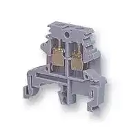
DIN Rail Mount Terminal Block, 2 Ways, 12 AWG, Screw, 35 A
⚠️ Reference pricing provided. In case of supply shortages, we will connect you with our trusted procurement partners to ensure your project's continuity.
- Manufacturer: TE CONNECTIVITY - ENTRELEC
- Product type: DIN Rail Terminal Blocks
- No. of Positions:2Ways; Wire Size AWG Min:-; Wire Size AWG Max:12AWG; Conductor Area CSA:-; Wire Connection Method:Screw; Rated Current:35A; Rated Voltage:750V; No. of Levels:1; Prod
- No. of Levels: 1
- Product Range: -
- Rated Current: 35A
- Rated Voltage: 750V
- No. of Positions: 2Ways
- Wire Size AWG Max: 12AWG
- Wire Size AWG Min: -
- Conductor Area CSA: -
- Wire Connection Method: Screw
| Delivery and price | |
|---|---|
| Units per pack | 1500 |
| Price | 0.786 € |
| Current stock | 10+ |
| Lead time | 30 days |
Datasheet

Technical catalogue

## **Gemini** Low voltage electric insulating switchboards

1SLC805001D0201

**Table of contents**

**Introduction Order codes Technical information**

**Overall dimensions**

**Code list**

**1**

**2 3**

**4**

**5**

ABB SACE

## **ABB SACE and its commitment to protecting the environment**

ABB SACE is one of the forerunners among the companies in the Group in dedicating considerable resources towards reaching its objectives of sustainable development and environmental protection. This is confirmed by the fact that all the company manufacturing sites have been awarded ISO 9001 quality certification and most of them have also been awarded ISO 14001 environmental management system certification. The plants in Frosinone and Patrica have also been awarded the Quality, Environment and Safety Integrated System certification and are certified in compliance with the BS 8800 Standards for health and safety in the workplace.

ABB SACE is actively involved in continuing the policy of improving environmental management by rationalizing the consumption of raw materials and energy, preventing pollution, respecting water and air, reducing noise levels to a minimum, reducing waste from production processes and carrying out periodic environmental checks at the main suppliers’ premises.

By using analysis tools such as LCA (Life Cycle Assessment), from the initial design stages ABB SACE assesses and improves the environmental performance of its products throughout their entire life cycle in order to guarantee maximum efficiency in technical and energy performance during operation, control and reduce environmental impact in the manufacturing stage and define end-of-life procedures.

All these goals and activities are the result of a far-sightedness in adopting ecological policies and methods of reducing environmental impact and, here too, ABB SACE is, as already seen in the quality of its products, a leader on the Italian company scene.

Plant in Marostica (Vicenza-Italy)

## **Introduction**

**1**

## **Index**

Characteristics of Gemini switchboards ................................................................................ **1** /2

ABB SACE

**1** /1

Characteristics of Gemini switchboards

## **Introduction**

## _Gemini, something completely different in switchboards_

ABB SACE’s Gemini range is revolutionizing the market of low **1** voltage electric insulating switchboards. |

The reason for this is that it is the first switchboard made in thermoplastic material, to which the co-injection molding technique gives the same mechanical characteristics as polyester. This means that it is extremely sturdy, with its rigid covering and expanded internal core. Moreover, it contains no fiberglass, a material that with time rises to the surface, jeopardizing the functioning and safety of switchboards made in polyester with which it is usually mixed. Gemini switchboards have IP66 degree of protection (IP40 with the door open and with the appropriate components installed) and a very high resistance to chemical and atmospheric agents. This is the reason why Gemini guarantees excellent performances even in particularly severe operating conditions.

**==> picture [4 x 36] intentionally omitted <==**

**----- Start of picture text -----**<br>
1SLC805003F0001<br>**----- End of picture text -----**<br>


_Gemini switchboards are made with co-injection, which ABB SACE is the first manufacturer in the electric field to use as a molding technique. This process obtains a “sandwich” of two materials with a compact external covering and an expanded core, guaranteeing the highest level of mechanical protection against impacts  (IK10) without the need to add hardening substances._

_Polyester is usually mixed with fiberglass, which, with wear, rises to the surface and can become a risk factor for skin burns that may occur during installation and maintenance and accidental contact._

_Moreover, it causes deterioration of the technical strength and lasting characteristics of the material to which it is added: Gemini, on the other hand, keeps its mechanical characteristics in the long term._

_The co-injection technique makes the manufacturing operations themselves safe because the products are completely finished when they come out of the mold without any flash or other surface irregularities._

## _Strong outside and versatile inside, Gemini is fit for all applications_

There are as many configurations as there are ABB devices for low voltage automation and distribution: moulded-case circuit breakers, modular circuit breakers, monitoring, control and signaling devices, wiring ducts and electrical connection systems.

**==> picture [4 x 35] intentionally omitted <==**

**----- Start of picture text -----**<br>
1SLC805002F0001<br>**----- End of picture text -----**<br>


All of these components give the “Gemini system” an enormous range of ad hoc solutions that are easy to assemble with the snap-on system.

ABB SACE

**1** /2

**==> picture [584 x 426] intentionally omitted <==**

**----- Start of picture text -----**<br>
ty<br>gear ef<br>rhs hea 4 tha * . id<br>ye i.<br>a re<br>r : :!<br>| — a | J<br>“wa ie a a<br>tee ene a4 | i<br>@ittcesss:: ———e Ss fa bs<br>oT as<br>y fo f a ee<br>a‘ | ok" sf:- a !<br>**----- End of picture text -----**<br>


## **Introduction**

## Characteristics of Gemini switchboards

Nothing can be compared with Gemini, even when the switchboards have reached the end of their life cycle: they are totally ecologically compatible. The material used to manufacture **1** them is 100% recyclable. Polyester, on the other hand, cannot be recovered.

Moreover, to make sure that correct disposal procedures are followed,  instructions are provided about how to identify materials and what to do with the product once it has served its useful purpose.

## _Quality and safety_

ABB’s Gemini is designed and built in compliance with reference Standards that define its constructional and functional characteristics.

_Gemini is made in a thermoplastic material that has a very low halogen content and is 100% recyclable._ a alil 77 _The environmental compatibility of Gemini is an_ ??,la“a7¥. _important objective right from the design phase where the Life Cycle Assessment (LCA) procedure, defined in_ \,74. _1990 during the Society of Environmental Toxicology and Chemistry Conference (Vermont, USA), is followed. Life Cycle Assessment is an objective method for analyzing the energy and environmental loads relating to a product, process or activity, carried out by identifying and quantifying energy, the materials used and emissions released into the environment. Divided into four phases, the assessment covers the entire life cycle of the product, process or activity, from the extraction and transformation of raw materials to manufacturing and distribution, and from usage to recycling and decommissioning._

In particular, the IP66 degree certifies that Gemini is totally protected against the infiltration of solid bodies and is resistant to the penetration of jets of water similar to sea waves. Absolute protection is provided by double insulation even in the event of indirect contact. Rated uninterrupted current can reach a threshold of 400 A.

Even in very difficult application circumstances, Gemini gives high-level performances, with resistance to fire and abnormal heat up to a temperature of 750 ° C and a functioning temperature from -25 ° C to 100 ° C. Moreover, the material with which it is manufactured retains its characteristics for a long time since it is not subject to corrosion by chemical or atmospheric agents. Also it does not turn yellow when exposed to UV rays.

ABB SACE

**1** /4

**==> picture [567 x 664] intentionally omitted <==**

**----- Start of picture text -----**<br>
na a ‘<br>Pe 5<br>7<br>7<br>|<br>**----- End of picture text -----**<br>


Characteristics of Gemini switchboards

## **Introduction**

_A  switchboard that is not just one system, but three_

Gemini is the result of design work conducted by ABB with the direct collaboration of **1** switchboard manufacturers, installers and designers who  considered versatility to be the discriminating element when purchasing a switchboard, equally as important as sturdiness and reliability.

Gemini fulfils this requirement by providing a product that can be used for three different purposes: in addition to the basic configuration it also provides the components necessary for equipping it as an automation switchboard or as a distribution and mixed switchboard.

In all applications, compatibility with ABB protection, control and monitoring products means that a real system of integrated and complementary functions can be configured.

Typical examples of some Gemini applications can be seen in installations in industrial production departments and on board machines, in galvanization plants and varnishing cabins, in petrol stations and carwashing plants, boiler-rooms, car parks, shopping malls and in any other environments where distribution and automation demand specific safety requirements and service continuity. Gemini also has flexible measurements, with six different box sizes and internal space to accommodate from 24 to 216 DIN modules.

To respect safety standards, all the switchboard’s components can be fixed to the base plate or to the box frame without ha-

_Written in full, its name “Protect IT Multipurpose Box Gemini” says that no switchboard is more reliable. Integration of Gemini with other ABB low voltage protection, monitoring and control products fulfils the objective of  offering the market a complete range of products and systems._

_In particular, Industrial[IT] is the solution ABB has developed for integrating company activities at all levels, in which each product is seen as one element of a single solution. Products and technologies are grouped into functional suites, each of which_

**==> picture [4 x 36] intentionally omitted <==**

**----- Start of picture text -----**<br>
1SLC805007F0001<br>**----- End of picture text -----**<br>


_measures, monitors, optimizes and supports a specific “block” of activities, interacting in a coordinated manner thanks to the platform created by ABB (AIP: Aspect Integrator Platform)._

_Not only are all the certified products interactive, but they also ensure that all the information needed to operate them is readily available in the latest edition: technical characteristics, installation, user and maintenance instructions, environmental certificates and declarations._

_More information is given in the section entitled Products and services/IndustrialIT on the ABB website www.abb.com_

aided design programs simulate all types of application conditions translating virtual checks into a process to improve the performances of Gemini so that it will be able to respond more accurately to market requirements.

ving to use any tools; wiring is carried out from the front followed by snapping the base plate or the frame onto the box. The patented frame is fitted with the cable duct incorporated in the uprights.

In its design, Gemini repeats the shapes and RAL 7035 grey color of the ArTu switchboards with which it can be configured as a main protection switchboard.

## _Experience and innovation_

Gemini has two central aspects. It is both the result of years of work in the production of installation material and the expression of the most advanced technology, from design to distribution.

In the laboratory, computer-

ABB SACE

**1** /6

**1**

**==> picture [41 x 7] intentionally omitted <==**

**----- Start of picture text -----**<br>
ABB SACE<br>**----- End of picture text -----**<br>


2

## Order codes

## Index

Basic configuration ................................................................................................................. **2** /2 Components for automation applications ............................................................................... **2** /6 Components for distribution and mixed applications ........................................................... **2** /10 Accessories .......................................................................................................................... **2** /16 Rapid selection table ............................................................................................................ **2** /20

ABB SACE

2/1

Characteristics

> PROTECTION IP66 (IEC EN 60529) Class II insulation

automation

distribution

accessories

> STRENGTH Thermoplastic material moulded in co-injection

Resistance to abnormal heat and fire up to a temperature of 750 ° C (IEC EN 60695-2-1) IK10 (IEC EN 50102) degree of resistance to impacts Protection against chemical and atmospheric agents (water, saline solutions, acids, basic agents, mineral oils, UV rays)

Operating temperature -25 ° C ÷ +100 ° C

> PERFORMANCE Rated uninterrupted current up to 400 A MS Rated service voltage up to 690 V

> FLEXIBILITY OF 6 sizes from 335x400x210 mm to 840x1005x360 mm (WxHxD, external dimensions) 1 2 USE DIN 24 to 216 modules = ° eae INSTALLATION-FRIENDLY > Snap-on mounting of all components in compliance with safety Standards

QUALITY AND > Compliance with international reference Standards EN 50298,  EN 60670, EN 60439-1 ENVIRONMENT IMQ mark according to Standard EN 50298 100% recyclable

2

## Order codes Basic configurations

In the basic configuration, Gemini switchboards are composed of boxes in six different sizes ranging from 335x400x210 mm to 840x1005x360 mm (WxHxD, external measurements) and with opaque or transparent doors.

In both versions, the doors are reversible and clip onto the hinges without the need to use

tools; the fact that they open at an angle of more than 180 ° means that it is easy to work on the components installed inside the switchboard. The seal applied by extrusion along the sides of the doors guarantees IP66 degree of protection. Access to the inside of the switchboard is protected by a standard double bit lock that can be

replaced by locks of another type available in the accessories.

Boxes and doors can be requested either separately or as combined “box + door” codes, to make filling out the order form more flexible.

Inside the packages, the door is always wrapped separately and inserted inside a pocket

that protects it from accidental damage until wiring is completed and the switchboard is installed.

Hole-cover plugs to guarantee IP protection and double insulation for wall mounting are also supplied with the pack together with the instruction sheet.

**==> picture [4 x 36] intentionally omitted <==**

**----- Start of picture text -----**<br>
1SLC805013F0001<br>**----- End of picture text -----**<br>


Gemini doors open at an angle of more than 180 ° giving easy access to the devices installed inside the switchboard.

**==> picture [165 x 98] intentionally omitted <==**

**----- Start of picture text -----**<br>
a<br>FOTO NUOVA<br>1SLC805015F0001<br>**----- End of picture text -----**<br>


No tools are needed for installation. The doors hook onto the hinges with special The special structure of the inner perimeter of the box ensures further protection hinge pins and are reversible. against the penetration of water. The box is supplied with a spirit level.

Rapid selection table ......................... page 2/20 Technical information ...................... page 3/1 Overall dimensions ........................... page 4/1 ~~|~~

ABB SACE

2/3

2

## Order codes Basic configurations

**==> picture [120 x 660] intentionally omitted <==**

**----- Start of picture text -----**<br>
1SLC805031F0001<br>**----- End of picture text -----**<br>


~~Size Dimensions Modules Codes Unit/Pack~~

## Boxes and doors

- Available in 6 sizes

- Single order code combined with box and transparent and opaque door

- Pack with door dismounted and wrapped separately

- Door designed so that it can be hooked onto hinges at both vertical sides and mounted without the use of tools

- To be mounted to the wall using internal holes or fixing brackets supplied as accessories

- Door opening at an angle of more than 180 °

- RAL 7035 grey color

- Doors supplied with 2 standard double bit locks (3 for sizes 5 and 6) that can be replaced with locks for ciphered key or with square/triangular impression (the standard triplex key is suitable for use with three types of impressions).

|1|External<br>WxHxD(mm)<br>335x400x210|Internal<br>WxHxD(mm)<br>250x300x180|Max no.<br>DIN mod.<br>24(12x2)|No. vertical mod.<br> (H=150 mm)<br>2|With transparent <br>door<br>1SL0211A00|With opaque<br>door<br>1SL0201A00|1/1|
|---|---|---|---|---|---|---|---|
|2|460x550x260|375x450x230|54(18x3)|3|1SL0212A00|1SL0202A00|1/1|
|3|460x700x260|375x600x230|72(18x4)|4|1SL0213A00|1SL0203A00|1/1|
|4|590x700x260|500x600x230|96(24x4)|4|1SL0214A00|1SL0204A00|1/1|
|5|590x855x360|500x750x330|120(24x5)|5|1SL0215A00|1SL0205A00|1/1|
|6|840x1005x360|750x900x330|216(36x6)|6|1SL0216A00|1SL0206A00|1/1|


Overall dimensions ........................... page 4/1

Technical information ...................... page 3/1

Rapid selection table ......................... page 2/20

ABB SACE

2/4

2

## Order codes Basic configurations

|1SLC805033F0001||~~Size~~<br>~~Internal dimensions~~<br>~~External dimensions~~<br>~~Codes~~<br>~~Unit/Pack~~<br>Conf./Imb.<br>Single box<br>WxHxD(mm)<br>WxHxD(mm)<br>1<br>335x400x210<br>250x300x180<br>1SL0221A00<br>1/1<br>2<br>460x550x260<br>375x450x230<br>1SL0222A00<br>1/1<br>3<br>460x700x260<br>375x600x230<br>1SL0223A00<br>1/1<br>4<br>590x700x260<br>500x600x230<br>1SL0224A00<br>1/1<br>5<br>590x855x360<br>500x750x330<br>1SL0225A00<br>1/1<br>6<br>840x1005x360<br>750x900x330<br>1SL0226A00<br>1/1<br>~~Size~~<br>~~Box dimensions~~<br>~~Codes~~<br>~~Unit/Pack~~<br>Single doors<br>Transparent<br>Opaque<br>WxHxD(mm)<br>door<br>door<br>1<br>335x400x210<br>1SL0241A00<br>1SL0231A00<br>1/1<br>2<br>460x550x260<br>1SL0242A00<br>1SL0232A00<br>1/1<br>3<br>460x700x260<br>1SL0243A00<br>1SL0233A00<br>1/1<br>4<br>590x700x260<br>1SL0244A00<br>1SL0234A00<br>1/1<br>5<br>590x855x360<br>1SL0245A00<br>1SL0235A00<br>1/1<br>6<br>840x1005x360<br>1SL0246A00<br>1SL0236A00<br>1/1|
|---|---|---|


Rapid selection table ......................... page 2/20 Technical information ...................... page 3/1 Overall dimensions ........................... page 4/1

ABB SACE

2/5

base

distribution accessories

## Order codes

## Components for automation applications

Gemini switchboards are deapplications, not only is it possigned to be perfectly compasible to select the box and door tible with ABB components for in the required size, but you can low voltage control and monialso select the base plate in one toring. of the three versions in the For these applications they can range.

For these applications they can range. be equipped with modular deAfter wiring with the ducts and vices belonging to the System the Fix-O-Rapid device, the pro _M_ range, with Tmax special standard adjustable feet moulded-case circuit-breakers and hooks must be fitted onto and control and signaling dethe base plate, allowing it to be vices, creating a truly integrated inserted inside the box at up to automation system. seven different depths and When deciding the Gemini laythree further levels of adjustout for control and monitoring ment: no tools need to be used

to carry out these operations. To finish the job, the inner door can be mounted (reversible and in insulating material), guaranteeing IP40 degree of protection when the switchboard door is open. No tools are needed unless the inner door is equipped with buttons, warning lights, etc.

The fixing hooks and feet supplied in the standard versions are applied without having to use tools, making it possible to install the base plate at seven different depths inside the switchboard. They can also be adjusted at three further positions.

**==> picture [4 x 189] intentionally omitted <==**

**----- Start of picture text -----**<br>
1SLC805018F0001<br>1SLC805021F0001<br>**----- End of picture text -----**<br>


Application of the inner door guarantees IP40 degree of protection when the switchboard door is open.

inside the switchboard. light-signaling devices.

The base plate can be snap-mounted inside the switchboard.

Example of the configuration of a switchboard for an automation application: some ABB control and protection devices are installed on the plate. The inner door is fitted with

2

Rapid selection table ......................... page 2/20 Technical information ...................... page 3/1 Overall dimensions ........................... page 4/1 ~~C—O~~

ABB SACE

2/7

2

## Order codes

## Components for automation applications

**==> picture [120 x 660] intentionally omitted <==**

**----- Start of picture text -----**<br>
1SLC805034F0001<br>**----- End of picture text -----**<br>


||~~Size of the switchboard~~<br>~~Code~~<br>~~Unit/Pack~~<br>Baseplates<br>• Available in three versions in blank or drilled metal and insulating material<br>• Positioning at 3 different depths for size 1, 4 different depths for sizes 2-3-4 and 7 different depths for sizes 5-6<br>(adjustments with 30 mm pitch)<br>• Supplied with feet and hooks adjustable at three further positions (with 7.5 mm pitch)<br>• Snap-on mounting<br>In blank metal<br>In drilled metal<br>Insulatingmaterial<br>1<br>1SL0259A00<br>1SL0275A00<br>1SL0267A00<br>1/6<br>2<br>1SL0260A00<br>1SL0276A00<br>1SL0268A00<br>1/6<br>3<br>1SL0261A00<br>1SL0277A00<br>1SL0269A00<br>1/4<br>4<br>1SL0262A00<br>1SL0278A00<br>1SL0270A00<br>1/4<br>5<br>1SL0263A00<br>1SL0279A00<br>1SL0271A00<br>1/4<br>6<br>1SL0264A00<br>1SL0280A00<br>1SL0272A00<br>1/2|
|---|---|


## Inner doors

- Available for size 2 to size 6 boxes

- Made in insulating material

- IP40 degree of protection with door open

- Designed so that door can be hinged onto both vertical sides

- Snap-on mounting and fixing

|1|-|-|
|---|---|---|
|2|1SL0252A00|1/4|
|3|1SL0253A00|1/2|
|4<br>5<br>6|1SL0254A00<br>1SL0255A00<br>1SL0256A00|1/2<br>1/2<br>1/1|


Overall dimensions ........................... page 4/1

Rapid selection table ......................... page 2/20 Technical information ...................... page 3/1

ABB SACE

2/8

Order codes Components for automation applications

2

**==> picture [105 x 562] intentionally omitted <==**

**----- Start of picture text -----**<br>
12<br>8<br>6<br>4<br>ø7<br>K<br>C<br>A<br>L<br>C<br>**----- End of picture text -----**<br>


**==> picture [4 x 36] intentionally omitted <==**

**----- Start of picture text -----**<br>
1SLC805035F0001<br>**----- End of picture text -----**<br>


||~~Code~~||~~Dimensions~~|~~Weight (kg/m) Unit/Pack-meters~~|~~Weight (kg/m) Unit/Pack-meters~~|
|---|---|---|---|---|---|
||Wiringducts|||||
||• Made in self-extinguishing thermoplastic material (UL 94||V0), resistant to abnormal heat and fire up to 960°C (IEC 695-2-1)|||
||• RAL 7035 grey|color||||
||• Available in version with 8/12 mm and 4/6 mm slots|||||
||• Base strip designed to snap onto Fix-O-Rapid<br>• Available in standard lengths of 2 m|||||
||With 8/12 mm|With 4/6 mm||||
||slots|slots|WxH (mm)|||
||05 019|05 119|15x17|0.06|46|
||05 033<br>05 043|05 133<br>05 143|25x30<br>25x40|0.21<br>0.25|58<br>48|
||05 063|05 163|25x60|0.24|34|
||05 083|05 183|25x80|0.29|28|
||05 094|05 194|25x100|0.46|20|
||05 035|05 135|40x30|0.27|40|
||05 045<br>05 065|05 145<br>05 165|40x40<br>40x60|0.31<br>0.34|30<br>22|
||05 085|05 185|40x80|0.38|36|
||05 095|05 195|40x100|0.53|28|
||05 037|05 137|60x30|0.38|52|
||05 047|05 147|60x40|0.46|40|
||05 067|05 167|60x60|0.47|32|
||05 087|05 187|60x80|0.50|24|
||05 096|05 196|60x100|0.73|20|
||05 049|05 149|80x40|0.47|32|
||05 069|05 169|80x60|0.52|24|
||05 089|05 189|80x80|0.59|16|
||05 097|05 197|80x100|0.91|14|
||05 051|05 151|100x40|0.55|24|
||05 071|05 171|100x60|0.59|20|
||05 091|05 191|100x80|0.68|16|
||05 098|05 198|100x100|1.06|8|
||05 053|05 153|120x40|0.65|20|
||05 073|05 173|120x60|0.73|14|
||05 093|05 193|120x80|0.89|12|
||05 099|05 199|150x100|1.37|8|


~~Code Description Unit/Pack-no. pieces~~

## Fix-O-Rapid

Rapid mounting device for attaching wiring ducts to the base plate: it snaps onto the plate after drilling a ø 7 mm hole. Two Fix-O-Rapid devices are enough for each wiring duct section. Fix-O-Rapid guarantees maximum insulation since it does not involve the use of any metal component inside the wiring duct.

If the wrong wiring duct is selected, it can be dismounted and a version with the same base and a different height can be attached to the Fix-O-Rapid.

|05|270|Rapid mounting device for wiring duct, W|25 mm|20/600|
|---|---|---|---|---|
|05<br>05<br>05<br>05|272<br>274<br>276<br>278|Rapid mountingdevice for wiringduct,W<br>Rapid mountingdevice for wiringduct,W<br>Rapid mountingdevice for wiringduct,W<br>Rapid mountingdevice for wiringduct,W|40 mm<br>60 mm<br>80 mm<br>100 mm|20/600<br>20/600<br>20/240<br>20/240|
|05|280|Rapid mountingdevice for wiringduct,W|120 mm|20/240|
|05|282|Rapid mountingdevice for wiringduct,W|150 mm|20/240|


Rapid selection table ......................... page 2/20

Overall dimensions ........................... page 4/1

Technical information ...................... page 3/1

ABB SACE

2/9

base

automation

accessories

Components for distribution and mixed applications

## Order codes

In distribution and mixed applications, the Gemini switchboard is designed to be fitted with System pro _M_ modular devices and Tmax moulded-case circuit breakers.

The frame is the load-bearing element of the configuration: DIN rails, partial modular plates and the special Tmax mounting and cabling kits are snapped onto the uprights. All the components can be adjusted to six different depths with a pitch of 12.5 mm and arranged at heights with a distance of 75 mm between the rows.

Blank or drilled front panels are applied to protect the equipment and these can be hinged onto both sides; the cables are housed inside the vertical wiring duct integrated in the uprights according to an exclusive ABB patent.

Wiring is carried out by pulling out the frame and working from the front; the ergonomic grip and the standard feet and snapon hooks supplied make it easy to insert it inside the switchboard after the job is finished.

The frame can be extracted to make wiring operations easier at the workbench.

**==> picture [4 x 36] intentionally omitted <==**

**----- Start of picture text -----**<br>
1SLC805022F0001<br>**----- End of picture text -----**<br>


The DIN rail is supplied with special hooks already in position for attaching to the uprights.

The depth at which the DIN rail, the modular plates, the kit for fixing the Tmax circuit breakers and the wiring duct are positioned can be adjusted with a simple sliding movement.

**==> picture [5 x 174] intentionally omitted <==**

**----- Start of picture text -----**<br>
1SLC805025F0001<br>1SLC805024F0001<br>**----- End of picture text -----**<br>


**==> picture [4 x 132] intentionally omitted <==**

**----- Start of picture text -----**<br>
1SLC805026F0001<br>1SLC805023F0001<br>**----- End of picture text -----**<br>


2

Fixing hooks and feet allow the frame to be snap-mounted inside the box.

The blank and drilled panels are hinged onto both sides; the description of the installed components can be kept in the special compartment protected by a transparent, hinged flange.

The upright with the incorporated wiring duct is an exclusive ABB patent that rationalizes the path of cables

**==> picture [4 x 36] intentionally omitted <==**

**----- Start of picture text -----**<br>
1SLC805063F0001<br>**----- End of picture text -----**<br>


inside the switchboard.

Rapid selection table ......................... page 2/20 Technical information ...................... page 3/1 Overall dimensions ........................... page 4/1 ~~CT~~

ABB SACE

2/11

2

## Order codes

## Components for distribution and mixed applications

**==> picture [120 x 660] intentionally omitted <==**

**----- Start of picture text -----**<br>
1SLC805036F0001<br>**----- End of picture text -----**<br>


||~~Size of the switchboard~~<br>~~Code~~<br>~~Unit/Pack~~<br>Uprights<br>• Incorporated vertical wiring duct (ABB patent)<br>• Snap-on mounting of all components (installation pitch of 75 mm)<br>• Snap-on insertion into box<br>• Depth of installed components adjusted at a pitch of 12.5 mm (4 positions for uprights of size 1 and 6 positions for the<br>remaining ones)<br>• Ergonomic grip to make it easy to insert and extract<br>1<br>1SL0283A00<br>1/4<br>2<br>1SL0284A00<br>1/4<br>3<br>1SL0285A00<br>1/4<br>4<br>1SL0285A00<br>1/4<br>5<br>1SL0286A00<br>1/2<br>6<br>1SL0287A00<br>1/1<br>~~Size of the switchboard~~<br>~~Modules per row~~<br>~~Code~~<br>~~Unit/Pack~~<br>DIN rail<br>• Two-sided version<br>• Supplied with mounting supports that snap onto uprights<br>• Depth adjustment on uprights<br>• Designed so that rapid Unifix L mounting bars can be snapped on<br>1<br>12<br>1SL0290A00<br>1/10<br>2<br>18<br>1SL0291A00<br>1/10<br>3<br>18<br>1SL0291A00<br>1/10<br>4<br>24<br>1SL0292A00<br>1/10<br>5<br>24<br>1SL0292A00<br>1/10<br>6<br>36<br>1SL0293A00<br>1/10|
|---|---|


Overall dimensions ........................... page 4/1

Rapid selection table ......................... page 2/20 Technical information ...................... page 3/1

ABB SACE

2/12

2

## Order codes

## Components for distribution and mixed applications

**==> picture [121 x 660] intentionally omitted <==**

**----- Start of picture text -----**<br>
1SLC805037F0001<br>**----- End of picture text -----**<br>


~~Size of the switchboard Code Unit/Pack~~

## Drilled panels

|•|**Supplied with DIN rail complete with supports to snap onto uprights and adjustable in depth**|**Supplied with DIN rail complete with supports to snap onto uprights and adjustable in depth**|**Supplied with DIN rail complete with supports to snap onto uprights and adjustable in depth**||
|---|---|---|---|---|
|•|Available in 1 module (H 150 mm) and 1+1/2 module (H 225 mm, sizes 2-6) dimensions||||
|•|Designed to be hinged onto both vertical sides||||
|•|Snap-on mounting onto uprights (in compliance|with reference Standards a tool must be used for removing the panel)|||
|•|Document pocket for storing descriptions of installed devices||||
|||1 module|1 + 1/2 module||
||1|1SL0307A00|-|1/8|
||2<br>3<br>4|1SL0308A00<br>1SL0308A00<br>1SL0309A00|1SL0313A00<br>1SL0313A00<br>1SL0314A00|1/8<br>1/8<br>1/4|
||5|1SL0309A00|1SL0314A00|1/4|
||6|1SL0310A00|1SL0315A00|1/2|


## Blank panels

- Available in 1/2 module (H 75 mm), 1 module (H 150 mm) and 2 modules (H 300 mm) dimensions

- • H 150 mm and H 300 panels designed to be hinged onto both vertical sides • Snap-on mounting onto uprights (in compliance with reference Standards a tool must be used for removing the panel)

||1/2 module||
|---|---|---|
|1|1SL0318A00|1/10|
|2|1SL0319A00|1/10|
|3|1SL0319A00|1/10|
|4|1SL0320A00|1/6|
|5|1SL0320A00|1/6|
|6|1SL0321A00|1/4|
||1 module||
|1|1SL0324A00|1/8|
|2|1SL0325A00|1/8|
|3|1SL0325A00|1/8|
|4|1SL0326A00|1/4|
|5|1SL0326A00|1/4|
|6|1SL0327A00|1/4|
||2 modules||
|1|1SL0330A00|1/6|
|2|1SL0331A00|1/6|
|3|1SL0331A00|1/6|
|4|1SL0332A00|1/4|
|5<br>6|1SL0332A00<br>1SL0333A00|1/4<br>1/4|


Rapid selection table ......................... page 2/20

Overall dimensions ........................... page 4/1

Technical information ...................... page 3/1

ABB SACE

2/13

2

## Order codes

## Components for distribution and mixed applications

**==> picture [120 x 660] intentionally omitted <==**

**----- Start of picture text -----**<br>
1SLC805038F0001<br>**----- End of picture text -----**<br>


||~~Size of the switchboard~~<br>~~Code~~<br>~~Unit/Pack~~<br>Partial modularplates<br>• Available in 1 module (H 150 mm) and 2 module (H 300 mm, sizes 2-6) dimensions<br>• Snap-on mounting onto uprights with depth adjustment<br>1 module<br>1<br>1SL0296A00<br>1/6<br>2<br>1SL0297A00<br>1/4<br>3<br>1SL0297A00<br>1/4<br>4<br>1SL0298A00<br>1/4<br>5<br>1SL0298A00<br>1/4<br>6<br>1SL0299A00<br>1/2<br>2 modules<br>1<br>-<br>-<br>2<br>1SL0302A00<br>1/4<br>3<br>1SL0302A00<br>1/4<br>4<br>1SL0303A00<br>1/4<br>5<br>1SL0303A00<br>1/4<br>6<br>1SL0304A00<br>1/2|
|---|---|


## Kit for installing Tmax moulded-case circuit breakers

- For installing Tmax moulded-case circuit breakers in fixed version with front terminals

- Composed of a plate with special drilled holes and a protection panel with vertical slots that can be hinged on both sides and snap-on mounted (in compliance with reference Standards a tool must be used for removing the panel)

- Available for sizes 2-6

- Version H 150 with drillings for Tmax T1 3 poles (with and without residual current releaser), Tmax T1 4 poles (with and without residual current releaser), Tmax T2 3 poles (with and without residual current releaser), Tmax T2 4 poles (without residual current releaser)

- Version H 300 with drillings for Tmax T2 4 poles (with residual current releaser), Tmax T3 3 poles (with and without residual current releaser), Tmax T3 4 poles (with and without residual current releaser)

- Snap-on mounting onto uprights with the possibility of adjusting the plate depth

||H 150 mm|H 300 mm||
|---|---|---|---|
|1|-|-|-|
|2|1SL0336A00|1SL0370A00|1/4|
|3<br>4<br>5<br>6|1SL0336A00<br>1SL0337A00<br>1SL0337A00<br>1SL0338A00|1SL0370A00<br>1SL0371A00<br>1SL0371A00<br>1SL0372A00|1/4<br>1/4<br>1/4<br>1/2|


When choosing the correct kit, see table on page 3/8.

Overall dimensions ........................... page 4/1

Technical information ...................... page 3/1

Rapid selection table ......................... page 2/20

ABB SACE

2/14

## Order codes

## Components for distribution and mixed applications

||e 2/20<br>Technical information ...................... page 3/1<br>Overall dimensions ........................... page 4/1<br>~~Size of the switchboard~~<br>~~Code~~<br>~~Unit/Pack~~<br>Wiringkit<br>• Composed of wiring duct in versions 25x60 mm and 40x60 mm (WxH, 8-12 mm slots) and Fix-O-Rapid<br>• Snap-on mounting on uprights with depth adjustment<br>Wiringduct  25x60 mm<br>Wiringduct  40x60 mm<br>1<br>1SL0353A00<br>1SL0360A00<br>1/4<br>2<br>1SL0354A00<br>1SL0361A00<br>1/4<br>3<br>1SL0354A00<br>1SL0361A00<br>1/4<br>4<br>1SL0355A00<br>1SL0362A00<br>1/4<br>5<br>1SL0355A00<br>1SL0362A00<br>1/4<br>6<br>1SL0356A00<br>1SL0363A00<br>1/4|
|---|---|
|d selection table ......................... pag|e 2/20<br>Technical information ...................... page 3/1<br>Overall dimensions ........................... page 4/1|


2

ABB SACE

2/15

base

automation distribution

## Order codes Accessories

Gemini switchboards have the same accessories for both automation and distribution applications, ensuring maximum versatility and integration of functions.

In particular, the ventilation and anti-condensation kits make it even safer for the devices to run, protecting them from the effects of heat and humidity while the wall brackets, pole mounting kit

and pedestal make it easier to install the switchboards in any context.

Three different kinds of locks are supplied for the doors with which it is possible to replace the standard double bit model. The universal drill bit can be used to open the side branch connections. Module covers hide the unused modules of the DIN rail guaranteeing IP40 pro-

tection when the door is open in distribution and mixed configurations.

Gemini wall-mounted installation using the special mounting brackets.

2

**==> picture [4 x 36] intentionally omitted <==**

**----- Start of picture text -----**<br>
1SLC805029F0001<br>**----- End of picture text -----**<br>


**==> picture [4 x 36] intentionally omitted <==**

**----- Start of picture text -----**<br>
1SLC805065F0001<br>**----- End of picture text -----**<br>


The standard locks supplied can be replaced by the version with ciphered key and handle or with square or triangular impression.

**==> picture [4 x 36] intentionally omitted <==**

**----- Start of picture text -----**<br>
1SLC805066F0001<br>**----- End of picture text -----**<br>


Rapid selection table ......................... page 2/20

**==> picture [4 x 36] intentionally omitted <==**

**----- Start of picture text -----**<br>
1SLC805027F0001<br>**----- End of picture text -----**<br>


The fact that Gemini switchboards can also be pole-mounted (see photo above) or mounted on a special pedestal (see photo at the side) makes them suitable for any application situation.

Overall dimensions ........................... page 4/1

Technical information ...................... page 3/1

ABB SACE

2/17

2

## Order codes Accessories

**==> picture [120 x 660] intentionally omitted <==**

**----- Start of picture text -----**<br>
1SLC805040F0001<br>**----- End of picture text -----**<br>


||~~Code~~<br>~~Description~~<br>~~Unit/Pack~~<br>Locks<br>• Available in three versions with ciphered key and handle, with triangular and square impressions<br>1SL0340A00<br>Lock with Yale type ciphered key and handle<br>1/10<br>1SL0341A00<br>Lock with triangular impression<br>1/10<br>1SL0339A00<br>Lock with square impression<br>1/10|
|---|---|


## Mounting elements

|•|Guarantee optimum wall, pole and floor mounting conditions|Guarantee optimum wall, pole and floor mounting conditions||
|---|---|---|---|
||1SL0342A00|Horizontal and vertical wall brackets|1/10|
||1SL0343A00|Pole mountingkit for sizes 1 switchboards|1/4|
||1SL0344A00|Pole mountingkit for sizes 2-3 switchboards|1/4|
||1SL0345A00|Pole mountingkit for sizes 4-5 switchboards|1/2|
||1SL0346A00|Pole mountingkit for size 6 switchboards|1/2|
||1SL0352A00|Floor mounting pedestal for sizes 1-4|1/1|


## Ventilation kit

|• <br>• <br>•|Composed of plastic grills and filter to ensure switchboard ventilation<br> IP42<br> The filter must be cleaned periodically<br>1SL0350A00<br>Ventilation kit||1/1|
|---|---|---|---|
|||||
||2/20<br>Technical information ...................... page 3/1|Overall dimensions ........................... page 4/1||


Rapid selection table ......................... page 2/20 Technical information ...................... page 3/1

ABB SACE

2/18

Order codes Accessories

2

||e 2/20<br>Technical information ...................... page 3/1<br>Overall dimensions ........................... page 4/1<br>~~Code~~<br>~~Description~~<br>~~Unit/Pack~~<br>Anti-condensation kit<br>• Kit in special material to prevent condensation from forming inside the switchboard: it include<br>**GORETM** MEMBRANE VENTING<br>• Impermeable to water (pressure): 1 bar<br>• Air flow: 68/h (dp = 70 mbar)<br>• 1 kit for sizes 1-2, 2 kits for sizes 3-4 and 3 kits for sizes 5-6 are recommended to guarantee adequate dissipation; in any<br>case the number of kits to be installed depend on the number and type of devices installed inside the switchboard.<br>1SL0351A00<br>Anti-condensation kit<br>1/6<br>Other accessories<br>12894<br>Universal drill bit<br>1/30<br>12863<br>Module covers in RAL 7035grey,4 modules<br>50/600<br>12851<br>Plastic spacer for installing modular devices and moulded-case circuit<br>breakers at the same depth<br>10/60|
|---|---|
|Rapid selection table ......................... pag|e 2/20<br>Technical information ...................... page 3/1<br>Overall dimensions ........................... page 4/1|
|||


ABB SACE

2/19

2

## Order codes Rapid selection table

**==> picture [512 x 13] intentionally omitted <==**

**----- Start of picture text -----**<br>
Basic configuration<br>**----- End of picture text -----**<br>


**==> picture [511 x 218] intentionally omitted <==**

**----- Start of picture text -----**<br>
|||||||||||||||
|---|---|---|---|---|---|---|---|---|---|---|---|---|---|
|F|A|
|D|
|E|
|B|
|C|
|No. of|
|Size|installable|No. of|External|Internal|Complete switchboard|Box|Door|
|DIN modules|vertical mod.|dimensions|dimensions|
|(mod. x row)|(H=150 mm)|A|B|C|D|E|F|Trasparent door|Opaque door|Transparent|Opaque|
|1|24 (12x2)|2|400|335|210|300|250|180|1SL0211A00|1SL0201A00|1SL0221A00|1SL0241A00|1SL0231A00|
|2|54 (18x3)|3|550|460|260|450|375|230|1SL0212A00|1SL0202A00|1SL0222A00|1SL0242A00|1SL0232A00|
|3|72 (18x4)|4|700|460|260|600|375|230|1SL0213A00|1SL0203A00|1SL0223A00|1SL0243A00|1SL0233A00|
|4|96 (24x4)|4|700|590|260|600|500|230|1SL0214A00|1SL0204A00|1SL0224A00|1SL0244A00|1SL0234A00|
|5|120 (24x5)|5|855|590|360|750|500|330|1SL0215A00|1SL0205A00|1SL0225A00|1SL0245A00|1SL0235A00|
|6|216 (36x6)|6|1005|840|360|900|750|330|1SL0216A00|1SL0206A00|1SL0226A00|1SL0246A00|1SL0236A00|

**----- End of picture text -----**<br>


Accessories common to the whole range

**==> picture [36 x 34] intentionally omitted <==**

**==> picture [51 x 39] intentionally omitted <==**

**==> picture [50 x 45] intentionally omitted <==**

**==> picture [512 x 89] intentionally omitted <==**

**----- Start of picture text -----**<br>
Size Lock with handle Lock with triangular impression Lock with square impression Installation brackets Pole installation kit<br>1 1SL0343A00<br>2 1SL0344A00<br>3 1SL0344A00<br>1SL0340A00 1SL0341A00 1SL0339A00 1SL0342A00<br>4 1SL0345A00<br>5 1SL0345A00<br>6 1SL0346A00<br>**----- End of picture text -----**<br>


ABB SACE

2/20

2

## Order codes Rapid selection table

**==> picture [513 x 416] intentionally omitted <==**

**----- Start of picture text -----**<br>
Components for automation Components for distribution<br>Base plate Inner door Uprights DIN rail Drilled panel Blank panel Modular plate<br>Blank Drilled Insulating H=150 mm H=225 mm H=75 mm H=150mm H=300 mm H=150 mm H=300 mm<br>1SL0259A00 1SL0275A00 1SL0267A00 - 1SL0283A00 1SL0290A00 1SL0307A00 - 1SL0318A00 1SL0324A00 1SL0330A00 1SL0296A00 -<br>1SL0260A00 1SL0276A00 1SL0268A00 1SL0252A00 1SL0284A00 1SL0291A00 1SL0308A00 1SL0313A00 1SL0319A00 1SL0325A00 1SL0331A00 1SL0297A00 1SL0302A00<br>1SL0261A00 1SL0277A00 1SL0269A00 1SL0253A00 1SL0285A00 1SL0291A00 1SL0308A00 1SL0313A00 1SL0319A00 1SL0325A00 1SL0331A00 1SL0297A00 1SL0302A00<br>1SL0262A00 1SL0278A00 1SL0270A00 1SL0254A00 1SL0285A00 1SL0292A00 1SL0309A00 1SL0314A00 1SL0320A00 1SL0326A00 1SL0332A00 1SL0298A00 1SL0303A00<br>1SL0263A00 1SL0279A00 1SL0271A00 1SL0255A00 1SL0286A00 1SL0292A00 1SL0309A00 1SL0314A00 1SL0320A00 1SL0326A00 1SL0332A00 1SL0298A00 1SL0303A00<br>1SL0264A00 1SL0280A00 1SL0272A00 1SL0256A00 1SL0287A00 1SL0293A00 1SL0310A00 1SL0315A00 1SL0321A00 1SL0327A00 1SL0333A00 1SL0299A00 1SL0304A00<br>Accessories for automation Accessories for distribution<br>Kit for<br>Wiring Tmax Fix-O-Rapid kit with wiring duct Module covers<br>Size ducts Fix-O-Rapid H=150 mm H= 300 mm 25x60 mm 40x60 mm RAL 7035<br>1 - - 1SL0353A00 1SL0360A00<br>2 1SL0336A00 1SL0370A00 1SL0354A00 1SL0361A00<br>3 1SL0336A00 1SL0370A00 1SL0354A00 1SL0361A00<br>See page 2/9 See page 2/9 12863<br>4 1SL0337A00 1SL0371A00 1SL0355A00 1SL0362A00<br>5 1SL0337A00 1SL0371A00 1SL0355A00 1SL0362A00<br>6 1SL0338A00 1SL0372A00 1SL0356A00 1SL0363A00<br>**----- End of picture text -----**<br>


**==> picture [511 x 106] intentionally omitted <==**

**==> picture [521 x 91] intentionally omitted <==**

**----- Start of picture text -----**<br>
Ventilation Anti-condensation Pedestal  Universal drill bit Depth<br>kit kit adapter<br>1SL0350A00 1SL0351A00 1SL0352A00 12894 12851<br>-<br>-<br>1SLC805002F0201<br>**----- End of picture text -----**<br>


ABB SACE

2/21

3

## Technical information

## Index

Compliance with Standards and technical characteristics ...................................................... **3** /2 IP degree of protection ............................................................................................................ **3** /4 IK degree of resistance to impacts .......................................................................................... **3** /5 Double insulation .................................................................................................................... **3** /6 Self-extinguishing tests ........................................................................................................... **3** /6 Resistance to chemical agents ............................................................................................... **3** /7 Installation of Tmax moulded-case circuit breakers ................................................................ **3** /8 Unifix L fast wiring system ....................................................................................................... **3** /9 Entrelec connection system .................................................................................................. **3** /10 Examples of orders ............................................................................................................... **3** /12 Component mounting distances ........................................................................................... **3** /15 Disposal instructions ............................................................................................................. **3** /17

ABB SACE

3/1

Technical information Compliance with Standards and technical characteristics

3

## ~~Reference Standards~~

Standard CEI EN 50298 (“Empty enclosures for low voltage switch-gear and control gear assemblies. General requirements.”) is the prescriptive reference for Gemini switchboards.

The object of Standard CEI EN 50298 is to formulate definitions, classifications, characteristics and test prescriptions for cases designed to be used as part of protection and operating equipment (switchboards) in compliance with the Standards of the EN 60439 series, that have a maximum rated voltage of 1000 V in alternating current for maximum frequencies of 1000 Hz or 1500 V in direct current and are suitable for general use in both internal and external applications. The Standard applies to empty enclosures, before the user has installed protection and operating devices inside them.

The Standard does not apply to enclosures with structural and functional characteristics that make them subject to other prescriptions (e.g. cases for domestic installations and the like). In this case Standards IEC 60670 – CEI 23-48 (“General requirements for enclosures for accessories for household and similar fixed electrical installations”) and CEI 23-49 (“Enclosures for accessories for household and similar fixed electrical installations. Part 2: particular requirements for enclosures for protection devices and accessories dissipating a considerable power in normal use”) apply.

On the basis of the indications of the ABB SACE technical characteristics’ table, the installer may have to certify compliance with Standards CEI 23-51 – EN 60439-1 – CEI 17-13-1 (“Part 1: standard equipment subject to type tests – AS – and non-standard equipment partially subject to type tests – ANS).

ABB SACE

3/2

3

## Technical information Technical characteristics

||Size<br>1<br>2<br>3<br>4<br>5<br>6<br>Gemini with transparent door<br>1SL0211A00<br>1SL0212A00<br>1SL0213A00<br>1SL0214A00<br>1SL0215A00<br>1SL0216A00<br>Gemini with opaque door<br>1SL0201A00<br>1SL0202A00<br>1SL0203A00<br>1SL0204A00<br>1SL0205A00<br>1SL0206A00<br>External dimensions WxHxD (mm) 335x400x210<br>460x550x260<br>460x700x260<br>590x700x260<br>590x855x360<br>840x1005x360<br>Internal dimensions WxHxD (mm) 250x300x180<br>375x450x230<br>375x600x230<br>500x600x230<br>500x750x330<br>750x900x330<br>IP degree<br>IP66<br>IP66<br>IP66<br>IP66<br>IP66<br>IP66<br>Double isolation<br>Yes<br>Yes<br>Yes<br>Yes<br>Yes<br>Yes<br>IK degree<br>10<br>10<br>10<br>10<br>10<br>10<br>GWT (°C)<br>750<br>750<br>750<br>750<br>750<br>750<br>Operating temperature<br>-25°C÷+100°C<br>-25°C÷+100°C<br>-25°C÷+100°C<br>-25°C÷+100°C<br>-25°C÷+100°C -25°C÷+100°C<br>No. of DIN modules<br>24 (12x2)<br>54 (18x3)<br>72 (18x4)<br>96 (24x4)<br>120 (24x5)<br>216 (36x6)<br>No. of vertical modules (H=150 mm)<br>2<br>3<br>4<br>4<br>5<br>6<br>Material<br>Thermoplastic<br>Thermoplastic<br>Thermoplastic<br>Thermoplastic<br>Thermoplastic<br>Thermoplastic<br>Color<br>Grey RAL7035<br>Grey RAL7035<br>Grey RAL7035<br>Grey RAL7035<br>Grey RAL7035<br>Grey RAL7035<br>Fast wiring system<br>Unifix L<br>Unifix L<br>Unifix L<br>Unifix L<br>Unifix L<br>Unifix L<br>No. of locks<br>2<br>2<br>2<br>2<br>3<br>3<br>Rated current In<br>≤400 A<br>≤400 A<br>≤400 A<br>≤400 A<br>≤400 A<br>≤400 A<br>Rated frequency<br>50-60 Hz<br>50-60 Hz<br>50-60 Hz<br>50-60 Hz<br>50-60 Hz<br>50-60 Hz<br>Maximum dissipation power(1)<br>45 W<br>72 W<br>85 W<br>102 W<br>156 W<br>248 W<br>STANDARD CEI EN 60439-1<br>Over-temperature (par. 8.2.1)(2)<br>- Max. dispersible power with<br>over-temperature of 25°C<br>40 W<br>65 W<br>77 W<br>91 W<br>133 W<br>205 W<br>- Max. dispersible power with<br>over-temperature of 30°C<br>45 W<br>72 W<br>85 W<br>102 W<br>156 W<br>248 W<br>- Max. dispersible power with<br>over-temperature of 35°C<br>52 W<br>85 W<br>100 W<br>121 W<br>187 W<br>299 W<br>- Max. dispersible power with<br>over-temperature of 40°C<br>62 W<br>100 W<br>118 W<br>143 W<br>221 W<br>355 W<br>Impulse withstand (par. 8.2.2)<br>- Rated service voltage<br>≤690 V<br>≤690 V<br>≤690 V<br>≤690 V<br>≤690 V<br>≤690 V<br>- Rated insulation voltage<br>≤800 V<br>≤800 V<br>≤800 V<br>≤800 V<br>≤800 V<br>≤800 V<br>- Rated impulse withstand voltage<br>8 kV<br>8 kV<br>8 kV<br>8 kV<br>8 kV<br>8 kV<br>Short circuit withstand (par. 8.2.3)<br>- Rated peak short-circuit current<br>-<br>-<br>-<br>-<br>-<br>-<br>~~Table of Gemini switchboards’ technical characteristics~~|
|---|---|


> (1) Maximum dissipation power data was obtained following the indications of **Standard CEI 23-49** , with a temperature difference of Dt=30 ° C.

> (2) **Note to paragraph 8.2.1 of Standard CEI EN 60439-1**

The table gives the thermal dissipation values of Gemini switchboards when they are wall-mounted. The dispersible power figures (in Watts) vary according to the overtemperature allowed in the accessible parts of the switchboard and must be compared with the total amount of power dissipated by all the components installed inside the switchboard taking into due account the factor of contemporaneity.

ABB SACE

3/3

Technical information IP degree of protection

3

## ~~IP degree of protection~~

As indicated in the following table, the IP degree of protection is expressed by two characteristic numbers depending on the behavior of the product to which it refers according to the prescriptions

## of CEI 70-1 and IEC 529 Standards.

With IP66 degree of protection, Gemini switchboards are totally protected against the penetration of dusts and sprays of seawater.

## First number: protection against the penetration of solid bodies

Second number: protection against the penetration of water

**==> picture [519 x 431] intentionally omitted <==**

**----- Start of picture text -----**<br>
|||||||
|---|---|---|---|---|---|
|IP|IP|
|0|0|
|No protection|No protection|
|1|ø 50 mm|1|
|Protection against the penetration|
|Protection against the penetration|
|of solid bodies with a diameter of|
|of drops of water falling vertically|
|over 50 mm|
|2|ø 12 mm|Protection against the penetration of|2|15|Protection against the penetration|
|solid bodies with a diameter of over|
|of drops of water falling at an|
|12 mm or a length of over 80 mm|angle of up to 15|°|from vertical|
|3|Protection against the penetration|3|60|Protection against the penetration|
|of solid bodies with a diameter or|of drops of water falling at an|
|thickness of over 2.5 mm|angle of up to 60|°|from vertical|
|4|Protection against the penetration|4|Protection against the penetration|
|of solid bodies with a diameter or|of splashes of water from all|
|thickness of over 1.0 mm|directions|
|5|5|
|Protection against the penetration|
|Protection against the penetration|
|of water sprayed by a hose from|
|of dusts|
|all directions|
|6|6|
|Protection against the penetration|
|Total protection against the|
|of sea water|
|penetration of dusts|
|1|[st]|number defined by Standards CEI 70-1 – IEC 60529|7|
|Protection against the penetration|
|of water during temporary|
|immersion|
|8|
|Protection against the penetration|
|of water during continual immer-|
|sion|

**----- End of picture text -----**<br>


- 2[nd] number defined by Standards CEI 70-1 - IEC 60529

ABB SACE

3/4

IK degree of resistance to impacts

## Technical information

## ~~IK degree of resistance to impacts~~

The IK degree is expressed in Joules in compliance with Standard CEI EN 50102.

**==> picture [511 x 510] intentionally omitted <==**

**----- Start of picture text -----**<br>
0.25 kg<br>IK 00 IK 06<br>No protection against impacts Resistance to impacts with<br>impact energy up to 1.00 J<br>0.25 kg 0.50 kg<br>IK 01 IK 07<br>Resistance to impacts with Resistance to impacts with<br>impact energy up to 0.150 J impact energy up to 2.00 J<br>0.25 kg 1.7 kg<br>IK 02 IK 08<br>Resistance to impacts with Resistance to impacts with<br>impact energy up to 0.200 J impact energy up to 5.00 J<br>0.25 kg 5 kg<br>IK 03 IK 09<br>Resistance to impacts with Resistance to impacts with<br>impact energy up to 0.350 J impact energy up to 10.00 J<br>0.25 kg 5 kg<br>IK 04 IK 10<br>Resistance to impacts with Resistance to impacts with<br>impact energy up to 0.500 J impact energy up to 20.00 J<br>0.25 kg<br>IK 05<br>Resistance to impacts with<br>impact energy up to 0.700 J<br>400 mm<br>56 mm<br>400 mm<br>80 mm<br>300 mm<br>140 mm 200 mm<br>200 mm<br>400 mm<br>280 mm<br>**----- End of picture text -----**<br>


3

ABB SACE

3/5

3

## Technical information

## Double insulation and self-extinguishing tests

## ~~Double insulation~~

Double insulation guarantees that Gemini is protected against indirect contacts on condition that the manufacturer’s instructions are observed when carrying out mounting and wiring operations on the switchboard and that the appropriate accessories are used (e.g. screw-cover caps).

Double insulation is indicated by the graphic symbol

## ~~Self-extinguishing tests~~

|Test text|Equipment<br>Compliance<br>Purpose<br>Test results<br>Test conditions<br>required<br>with Standards of the test<br>Heat<br>Length<br>Characteristic<br>source<br>oftest<br>elements|
|---|---|
|GLOW-WIRE TEST|<br>IEC 695-2-1<br>To assess the danger of<br>If a flame is generated,<br>Glow wire<br>30 sec.<br>Assessment<br>CEI 50-11<br>fire by simulating thermal<br>it must go out within<br>ø 4 mm<br>of the time<br>stresses produced<br>30 seconds of removing<br>it takes for<br>by heat sources or<br>the glow wire.<br>the flame to<br>by ignition (e.g. glowing<br>The test is conducted<br>go out<br>elements, resistances<br>at temperatures of:<br>overloaded for short<br>- 650°C<br>intervals)<br>- 750°C<br>- 850°C<br>- 960°C<br>1SLC805043F0001|


ABB SACE

3/6

Ammon

Toluene Methan Wine

**==> picture [36 x 4] intentionally omitted <==**

**----- Start of picture text -----**<br>
1SLC805004F0201<br>**----- End of picture text -----**<br>


3

## Technical information Integration with ABB products

## ~~Installation of Tmax moulded-case circuit breakers~~

The table indicates the type of installation required for the different versions of Tmax moulded-case circuit breakers in Gemini switchboards.

Before carrying out wiring operations check compliance with Standards on the basis of the technical characteristics of the switchboard and circuit breaker (CEI EN 60439-1).

|Size|Installation<br>Tmax T1<br>Tmax T2<br>Tmax T3<br>Tmax T4<br>Tmax T5|
|---|---|
|1|D<br>•<br>•<br>•|
||O1<br>•<br>•|
||T<br>•<br>•<br>•<br>•(3)<br>•<br>(3)|
|2|D<br>•<br>•<br>•|
||K1<br>•<br>•(1)|
||K2<br>•(2)<br>•|
||O1<br>•<br>•<br>•<br>•(4)|
||O2<br>•<br>•<br>•<br>•<br>•(3)|
||T<br>•<br>•<br>•<br>•<br>•|
|3|D<br>•<br>•<br>•|
||K1<br>•<br>•(1)|
||K2<br>•(2)<br>•|
||O1<br>•<br>•<br>•<br>•(4)|
||O2<br>•<br>•<br>•<br>•<br>•(3)|
||T<br>•<br>•<br>•<br>•<br>•|
|4|D<br>•<br>•<br>•|
||K1<br>•<br>•(1)|
||K2<br>•(2)<br>•|
||O1<br>•<br>•<br>•<br>•(4)|
||O2<br>•<br>•<br>•<br>•<br>•|
||T<br>•<br>•<br>•<br>•<br>•|
|5|D<br>•<br>•<br>•|
||K1<br>•<br>•(1)|
||K2<br>•(2)<br>•|
||O1<br>•<br>•<br>•<br>•(4)|
||O2<br>•<br>•<br>•<br>•<br>•|
||T<br>•<br>•<br>•<br>•<br>•|
|6|D<br>•<br>•<br>•|
||K1<br>•<br>•(1)|
||K2<br>•(2)<br>•|
||O1<br>•<br>•<br>•<br>•(4)|
||O2<br>•<br>•<br>•<br>•<br>•|
||T<br>•<br>•<br>•<br>•<br>•|


Caption

- **D** , installation on DIN rail

- **K1** , installation with Tmax kit H = 150 (holes made)

- **K2** , installation with Tmax kit H = 300 (holes made)

- **O1** , installation on modular plate (1 module, H = 150 mm)

- **O2** , installation on modular plate (2 modules, H = 300 mm)

- **T** , installation on total base plate

- **•**[(1)] , Tmax T2 3 poles (with or without residual current release) and Tmax T2 4 poles (without residual current release)

- **•**[(2)] , Tmax T2 4 poles (with residual current release)

- **•**[(3)] , only version without residual current release

- **•**[(4)] , only version with 3 poles

ABB SACE

3/8

Technical information Integration with ABB products

3

## ~~Unifix L fast wiring system~~

Unifix is the system patented by ABB for the fast and safe wiring of equipment in the System pro _M_ range and Tmax and Isomax moulded-case circuit breakers. It is available in three versions, of which Unifix L is the one most suitable for installing in Gemini switchboards with rated currents of up to 100 A and short-circuit currents of up to 25 kA.

Unifix L is composed by assembling its components listed in the following tables that should be referred to when ordering.

The busbars are housed in a system of ducts with a capacity of 100 A and short-circuit current of 25 kA. They are supplied in two and four-pole versions with from 12 to 32 modules. They snap onto the back of the DIN rail.

**==> picture [137 x 103] intentionally omitted <==**

||Code|Description|Pack/Pieces|
|---|---|---|---|
||ED2993|Busbar 100 A,2poles,12 modules|1/6|
||ED3009|Busbar 100 A,2poles,18 modules|1/6|
|1SLC805044F0001|ED3017<br>ED3025<br>ED2944<br>ED2951<br>ED2969<br>ED2977|Busbar 100 A,2poles,24 modules<br>Busbar 100 A,2poles,36 modules<br>Busbar 100 A,4poles,12 modules<br>Busbar 100 A,2poles,18 modules<br>Busbar 100 A,4poles,24 modules<br>Busbar 100 A,4poles,36 modules|1/6<br>1/6<br>1/6<br>1/6<br>1/6<br>1/6|


Connections are made in copper, cut to size and bent to allow power supply between the terminals of the modular System pro _M_ devices and the Unifix system busbars. They are supplied in the versions L1, L2, L3, N and 1p+N depending on the polarity of the device to be wired.

**==> picture [34 x 67] intentionally omitted <==**

**==> picture [71 x 59] intentionally omitted <==**

|1SLC805045F0001|Code<br>ED3355<br>ED3363<br>ED3371|Description<br>Connections<br>Connections<br>Connections|Pack/Pieces<br>with 2 cables,40 A<br>1/6<br>with 3 cables,40 A<br>1/6<br>with 4 cables,40 A<br>1/6|Pack/Pieces<br>with 2 cables,40 A<br>1/6<br>with 3 cables,40 A<br>1/6<br>with 4 cables,40 A<br>1/6|
|---|---|---|---|---|
||ED3074|Connections|1P+N,40 A,for DS 121,1 mod.|1/10|
||ED3272|Connections|L1-N,40 A,for S9..1N with neutral on the right|1/10|
||ED3280|Connections|L2-N,40 A,for S9..1N with neutral on the right|1/10|
||ED3298|Connections|L3-N,40 A,for S9..1N with neutral on the right|1/10|
||ED3033|Connections|L1,100 A|1/10|
||ED3041|Connections|L2,100 A|1/10|
||ED3058|Connections|L3,100 A|1/10|
||ED3066|Connections|N,100 A|1/10|


Feeder modular devices are available with and without cable. Modular devices with cable have a capacity of 36 A and 2-module dimensions; they are supplied in two and four pole versions. Modular devices with cable have a capacity of 100 A and 1-module dimensions; they are supplied in the L1, L2, L3 and N version. Both modular devices connect to the conductors feeding the busbars directly when installation of the main line switch is not envisaged.

**==> picture [35 x 104] intentionally omitted <==**

**==> picture [63 x 51] intentionally omitted <==**

||Code|Description<br>Pack/Pieces|Description<br>Pack/Pieces|
|---|---|---|---|
||ED3082|Feeder modular device with cable,63 A,2poles,L 250 mm|1/6|
|1SLC805046F0001|ED3090<br>ED3405<br>ED3413<br>ED3439|Feeder modular device with cable,63 A,4poles,L 250 mm<br>Feeder modular device with cable,63 A,4poles,L 400 mm<br>Feeder modular device with cable,63 A,4poles,L 800 mm<br>Feeder modular device with cable,63 A,4poles,L 1500 mm|1/6<br>1/6<br>1/6<br>1/6|
||ED3101|Feeder modular device without cable,100 A,L1|1/10|
||ED3102|Feeder modular device without cable,100 A,L2|1/10|
||ED3103|Feeder modular device without cable,100 A,L3|1/10|
||ED3104|Feeder modular device without cable,100 A,N|1/10|


Uni-polar feed terminals are available in 63 A and 100 A versions. They connect directly to the front terminals on the modular circuit breakers feeding the busbars through the main line switch. They are designed for the connection of a conductor with a 32 mm[2] and 25 mm[2] section respectively

|Code|Description|Pack/Pieces|
|---|---|---|
|ED3100|Terminals for 100 A feed for 35 mm2 cable|1/10|
|ED3140|Terminals for 63 A feed for 25 mm2 cable|1/10|


ABB SACE

3/9

3

## Technical information Integration with ABB products

**==> picture [525 x 645] intentionally omitted <==**

**----- Start of picture text -----**<br>
Electrical connection systems<br>Member of ABB Group<br>MA 2,5/5 MA 2,5/5.D2 M 4/6 MS 4/6 M 4/6.D2 M 6/8<br>Pitch<br>(mm) 5 5 6 6 6 8<br>Maximum section<br>(mm [2] ) 2,5 2,5 4 4 4 6<br>Connection<br>0115 486.03 0115 490.13 0115 116.07 0115 265.24 0115 271.22 0115 118.11<br>Neutral<br>0125 486.05 0125 490.15 0125 116.01 0125 265.26 0125 126.03 0125 118.13<br>Protection<br>0165 488.27 - 0165 113.16 - - 0165 114.17<br>Term. Plate<br>0118 368.16 0118 499.23 0118 368.16 0113 885.01 0118 499.23 0118 368.16<br>Head separator<br>0116 728.25 0116 720.21 0113 003.10 - 0113 482.05 0113 003.10<br>Test plug<br>ø 2 mm 0163 046.24 0164 950.00 0163 043.21 - 0163 070.00 0163 043.21<br>Control<br>device 0105 028.21 0173 058.02 0173 059.03 0173 059.03 0163 218.05 0173 060.00<br>Colour<br>Test plug<br>ø 2 mm 0007 865.26 0007 865.26 0007 865.26 0007 865.26 0007 865.26 0007 865.26<br>IP20 inter. bar<br>10 poles 0176 282.23 0176 740.11 0176 667.04 - 0179 672.21 0176 673.02<br>IP20 inter. bar<br>without screw 0199 443.24 - 0299 702.14 - - 0299 720.11<br>10 poles<br>Protection<br>plate - - 0163 427.17 - - 0163 428.20<br>0163 433.15 0163 433.15<br>Combs<br>10 poles 0113 544.12 0113 544.12 0113 548.26 0113 548.26 0163 311.22 0163 313.24<br>Shielding<br>bar 0178 745.14 0173 530.24 0178 745.14 - - -<br>1SLC805048F0001<br>1SLC805047F0001<br>**----- End of picture text -----**<br>


ABB SACE

3/10

Technical information Integration with ABB products

**==> picture [517 x 65] intentionally omitted <==**

**----- Start of picture text -----**<br>
1SLC805049F0001<br>**----- End of picture text -----**<br>


||||||1SLC805049F0001|
|---|---|---|---|---|---|
|/8.D2<br>8<br>6<br>501.12<br>-<br>-<br>656.25<br>482.05<br>043.21<br>-<br>865.26<br>673.02<br>720.11<br>-<br>-<br>-<br>MS 6/8<br>8<br>6<br>0115 278.01<br>0125 278.03<br>-<br>0114 195.06<br>-<br>-<br>0173 060.00<br>0007 865.26<br>-<br>-<br>-<br>0163 313.24<br>-|M 10/10|M 16/12|M 35/16|M 70/22<br>22<br>70<br>0115 216.13<br>0125 126.15<br>0165 596.13<br>without rail<br>0113 065.15<br>0113 851.16<br>terminal plate<br>separat.<br>-<br>-<br>-<br>-<br>-<br>0173 328.05<br>0173 323.20<br>-<br>-|M 95/26<br>26<br>95<br>0115 556.10<br>0125 556.12<br>0165 556.22<br>without rail<br>-<br>-<br>-<br>-<br>-<br>-<br>-<br>-<br>-<br>-|
||10|12|16|||
||10|16|35|||
||0115 120.17|0115 129.14|0115 124.07|||
||0125 120.11|0125 129.16|0125 124.01|||
||0165 115.10|0165 130.23|0165 111.14|||
||0118 368.16|0118 618.01|0118 233.27|||
||0113 003.10|0113 102.10<br>terminal plate<br>separat.|-|||
||0163 043.21|0163 043.21|0168 237.05<br>ø 4mm|||
||-|-|-|||
|||||||
||0007 865.26|0007 865.26|0167 860.01<br>ø 4mm|||
||0176 679.10|0179 631.03|0179 617.05<br>no IP20|||
||-|-|-|||
||0163 429.21<br>0163 433.15|0163 430.26<br>0163 432.14|0163 431.13<br>0173 147.20|||
||0163 315.26|-|-|||
||-|-|-|||


3

ABB SACE

3/11

Technical information Examples of orders

3

## ~~Examples of orders~~

The selection of components for the configuration of Gemini switchboards depends on the space available and the type of application. Two examples for each size are given below.

**==> picture [98 x 99] intentionally omitted <==**

**==> picture [4 x 36] intentionally omitted <==**

**----- Start of picture text -----**<br>
1SLC805051F0001<br>**----- End of picture text -----**<br>


**==> picture [87 x 103] intentionally omitted <==**

**==> picture [4 x 36] intentionally omitted <==**

**----- Start of picture text -----**<br>
1SLC805052F0001<br>**----- End of picture text -----**<br>


## Size 1

|Size 1|||
|---|---|---|
|||Distribution|
|1SL0211A00||Box + transparent door|
|1SL0283A00||Uprights|
|1SL0307A00|(x2)|1-mod. drilledpanel + DIN rail|


||Automation|
|---|---|
|1SL0201A00|Box + opaque door|
|1SL0259A00|Metal baseplate|
|1SL0342A00|Wall-mountingbrackets|


**==> picture [118 x 127] intentionally omitted <==**

**==> picture [4 x 36] intentionally omitted <==**

**----- Start of picture text -----**<br>
1SLC805053F0001<br>**----- End of picture text -----**<br>


**==> picture [106 x 121] intentionally omitted <==**

**==> picture [4 x 36] intentionally omitted <==**

**----- Start of picture text -----**<br>
1SLC805054F0001<br>**----- End of picture text -----**<br>


## Size 2

|Size 2||||
|---|---|---|---|
||Distribution/Mixed||Automation|
|1SL0212A00|Box + transparent door|1SL0202A00|Box + opaque door|
|1SL0284A00|Uprights|1SL0260A00|Metal baseplate|
|1SL0297A00|Modularplate 1 mod.|1SL0252A00|Inner door|
|1SL0325A00|Blankpanel 1 mod.|Vedipag. 2/9|Wiringduct|
|1SL0313A00|Drilledpanel 1+1/2 mod. + DIN rail|Vedipag. 2/9|Fix-O-Rapid|
|1SL0319A00|Blankpanel 1/2 mod.|||
|12863|Module covers|||


ABB SACE

3/12

Technical information Examples of orders

3

**==> picture [118 x 147] intentionally omitted <==**

**==> picture [4 x 35] intentionally omitted <==**

**----- Start of picture text -----**<br>
1SLC805055F0001<br>**----- End of picture text -----**<br>


**==> picture [132 x 159] intentionally omitted <==**

**==> picture [4 x 36] intentionally omitted <==**

**----- Start of picture text -----**<br>
1SLC805056F0001<br>**----- End of picture text -----**<br>


## Size 3

||Distribution/Mixed||Automation|
|---|---|---|---|
|1SL0213A00|Box + transparent door|1SL0203A00|Box + opaque door|
|1SL0285A00|Uprights|1SL0269A00|Base insulating plate|
|1SL0336A00|Kit for Tmax|1SL0253A00|Inner door|
|1SL0308A00 (x2)|Drilledpanel 1 mod. + DIN rail|Seepage 2/9|Wiringduct|
|1SL0291A00|DIN rail|Seepage 2/9|Fix-O-Rapid|
|1SL0325A00|Blankpanel 1 mod.|1SL0342A00|Wall-mountingbrackets|
|Seepages 3/10-3/11|Entrelec terminals|||


**==> picture [128 x 151] intentionally omitted <==**

**==> picture [4 x 36] intentionally omitted <==**

**----- Start of picture text -----**<br>
1SLC805057F0001<br>**----- End of picture text -----**<br>


**==> picture [129 x 152] intentionally omitted <==**

**==> picture [4 x 36] intentionally omitted <==**

**----- Start of picture text -----**<br>
1SLC805058F0001<br>**----- End of picture text -----**<br>


## Size 4

||Distribution/Mixed||Automation|
|---|---|---|---|
|1SL0214A00|Box + transparent door|1SL0204A00|Box + opaque door|
|1SL0285A00|Uprights|1SL0262A00|Metal baseplate|
|1SL0309A00 (x3)|Drilledpanel 1 mod. + DIN rail|1SL0254A00|Inner door|
|1SL0326A00|Blankpanel 1 mod.|Seepage 2/9|Wiringduct|
|1SL0355A00 (x2)|Wiringkit 25x60 mm|Seepage 2/9|Fix-O-Rapid|
|1SL0292A00|DIN rail|1SL0345A00|Fixingonpole kit|
|12863|Module covers|||
|Vedipagg. 3/10-3/11|Entrelec terminals|||


ABB SACE

3/13

Examples of orders

3

## Technical information

**==> picture [4 x 36] intentionally omitted <==**

**----- Start of picture text -----**<br>
1SLC805059F0001<br>**----- End of picture text -----**<br>


**==> picture [4 x 36] intentionally omitted <==**

**----- Start of picture text -----**<br>
1SLC805060F0001<br>**----- End of picture text -----**<br>


Size 5

Distribution/Mixed Automation 1SL0215A00 Box + transparent door 1SL0205A00 Box + opaque door 1SL0286A00 Uprights 1SL0279A00 Drilled base plate 1SL0337A00 Kit for Tmax 1SL0255A00 Inner door 1SL0303A00 Modular plate 2 mod. See page 2/9 Wiring duct 1SL0332A00 Blank panel 2 mod. See page 2/9 Fix-O-Rapid 1SL0314A00 Drilled panel 1+1/2 mod. 1SL0342A00 Wall-mounting brackets 1SL0320A00 Blank panel 1/2 mod. 1SL0350A00 Ventilation kit 12863 Module covers

**==> picture [482 x 226] intentionally omitted <==**

**----- Start of picture text -----**<br>
|||||||
|---|---|---|---|---|---|
|Size 6|
|Distribution/Mixed|Automation|
|1SL0216A00|Box + transparent door|1SL0206A00|Box + opaque door|
|1SL0288A00|Uprights|1SL0264A00|Metal base plate|
|1SL0304A00|Modular plate 2 mod.|1SL0256A00|Inner door|
|1SL0333A00|Blank panel 2 mod.|See page 2/9|Wiring duct|
|1SL0315A00|Drilled panel 1+1/2 mod.|See page 2/9|Fix-O-Rapid|
|1SL0321A00|Blank panel 1/2 mod.|1SL0341A00|(x3)|Triangular lock|
|1SL0310A00|(x2)|Panel with holes 1 mod.|1SL0351A00|(x3)|Anti-condensation kit|
|1SL0356A00|Wiring kit 25x60 mm|
|1SL0363A00|Wiring kit 40x60 mm|

**----- End of picture text -----**<br>


ABB SACE

3/14

3

## Technical information Component mounting distances

## ~~Component mounting distances~~

The reference mounting distances between components for the functional configuration of Gemini switchboards are shown in the diagrams.

**==> picture [511 x 210] intentionally omitted <==**

**----- Start of picture text -----**<br>
|||||||||
|---|---|---|---|---|---|---|---|
|Automation|
|components|
|c|
|f|
|p|f|
|f = distance|c = distance mounting|p = distance inner|f = distance inner|
|size|mounting|plate/floor|plate/inner door|size|door/door|door/floor|
|MIN.|MAX.|MIN.|MAX.|1|-|-|
|1|16.3|91|-|-|2|63|177|
|2|36.4|140|33.5|139|3|63|177|
|3|36.4|140|33.5|139|4|63|177|
|4|36.4|140|33.5|139|5|63|277|
|5|47|244|33.5|228|6|63|277|
|6|47|244|33.5|228|

**----- End of picture text -----**<br>


**==> picture [155 x 113] intentionally omitted <==**

**----- Start of picture text -----**<br>
Distribution<br>components d<br>D<br>**----- End of picture text -----**<br>


**==> picture [42 x 113] intentionally omitted <==**

**----- Start of picture text -----**<br>
d<br>**----- End of picture text -----**<br>


**==> picture [250 x 172] intentionally omitted <==**

**----- Start of picture text -----**<br>
|||||||
|---|---|---|---|---|---|
|d = distance drilled panel/plate|
|pos. 1|pos. 2|pos. 3|pos. 4|pos. 5|pos. 6|
|54.7|67.2|79.7|92.2|-|-|
|54.7|67.2|79.7|92.2|104.7|117.2|
|54.7|67.2|79.7|92.2|104.7|117.2|
|54.7|67.2|79.7|92.2|104.7|117.2|
|54.7|67.2|79.7|92.2|104.7|117.2|
|54.7|67.2|79.7|92.2|104.7|117.2|
|D = distance blank panel/plate|
|pos. 1|pos. 2|pos. 3|pos. 4|pos. 5|pos. 6|
|71.5|84|96.5|109|-|-|
|71.5|84|96.5|109|121.5|134|
|71.5|84|96.5|109|121.5|134|
|71.5|84|96.5|109|121.5|134|
|71.5|84|96.5|109|121.5|134|
|71.5|84|96.5|109|121.5|134|

**----- End of picture text -----**<br>


d = distance drilled panel/DIN rail

**==> picture [255 x 74] intentionally omitted <==**

**----- Start of picture text -----**<br>
||||||||
|---|---|---|---|---|---|---|
|size|pos. 1|pos. 2|pos. 3|pos. 4|pos. 5|pos. 6|
|1|51|63.5|76|88.5|-|-|
|2|51|63.5|76|88.5|101|113.5|
|3|51|63.5|76|88.5|101|113.5|
|4|51|63.5|76|88.5|101|113.5|
|5|51|63.5|76|88.5|101|113.5|
|6|51|63.5|76|88.5|101|113.5|

**----- End of picture text -----**<br>


Measurements are expressed in millimeters

ABB SACE

3/15

## Technical information Component mounting distances

3

**==> picture [519 x 205] intentionally omitted <==**

**----- Start of picture text -----**<br>
p f<br>p f<br>p = distance drilled f = distance drilled p = distance blank f = distance blank<br>size panel/door panel/floor size panel/door panel/floor<br>1 44 145 1 26.5 162<br>2 44 197 2 26.5 214<br>3 44 197 3 26.5 214<br>4 44 197 4 26.5 214<br>5 44 297 5 26.5 314<br>6 44 297 6 26.5 314<br>1SLC805006F0201<br>**----- End of picture text -----**<br>


Measurements are expressed in millimeters

ABB SACE

3/16

Technical information Disposal instructiones

3

## ~~Information about how to dispose of Gemini switchboards when they reach the end of their life~~

Instructions are given below about the procedures to adopt when disposing of Gemini switchboards at the end of their life cycle. The text is drafted in the form of a table referring to Standard CEI 308-1 “Information table concerning the end of life of electric and electronic products and a compilation guide”, 2002-04, ed. 1, pamphlet number 308-1 6454.

## Section I –  Global product specification

|Name||Type of product|Type of product||
|---|---|---|---|---|
|Size|||||
||With transparent door|With opaque door|Rated weight (kg)|External dimensions WxHxD (mm)|
|1|1SL0211A00|1SL0201A00|4,3|335x400x210|
|2<br>3<br>4|1SL0212A00<br>1SL0213A00<br>1SL0214A00|1SL0202A00<br>1SL0203A00<br>1SL0204A00|7,9<br>9,5<br>12,0|460x550x260<br>460x700x260<br>590x700x260|
|5|1SL0215A00|1SL0205A00|17,8|590x855x360|
|6|1SL0216A00|1SL0206A00|21,1|840x1005x360|


## Section II –  Global product table

General code: CER 17 02 03 plastic (more than 95% of the product’s weight)

**==> picture [515 x 299] intentionally omitted <==**

**----- Start of picture text -----**<br>
No. of the Diagram Quantity Material Symbol Dangerousness CER Code<br>component part % over description (Yes/No)<br>(P1, P2, etc.) total weight<br>P1/BOX Polypropylene No 17 02 03<br>P5/ACCESSORIES<br>P2/ROOF >PP<<br>~ 80%<br>P2/ROOF Polypropylene No 17 02 03<br>>PP<<br>P3/DOOR ~ 20% Polycarbonate No 17 02 03<br>>PC<<br>P4/ACCESSORIES < 5% Steel - No 17 04 05<br>P3/DOOR<br>P1/BOX<br>P4/ACCESSORIES<br>P5/ACCESSORIES < 5% Brass - No 17 04 01<br>1SLC805016F0201<br>**----- End of picture text -----**<br>


ABB SACE

3/17

3

## Technical information Disposal instructiones

## Section III –  Components to be removed from the product and sent for separate treatment

Refer to section II of the table for a description of the materials.

## Notes for recovery and disposal

At the end of its life, after separating it from components, the product can be sent to be recovered. The product is not biodegradable: do not dispose of it in the environment.

The product/waste product is assimilable as solid urban waste. It must be incinerated or disposed of in compliance with current EEC, national and local regulations. You are recommended to check all reutilization possibilities.

## Other recommendations

The information in this table relates to the product in the condition it was supplied. Assembled parts coming from different supplies must be treated separately according to the reference specifications of the respective manufacturers.

## Section IV –  Safety instructions

## Handling

No special instructions. Refer to the general regulations concerning hygiene on the workplace when using. The product’s main components contain mineral additives and coloring agents in concentrations that comply with current European Directives at the time this catalogue went to press: they do not contain substances classified as dangerous.

## Transport

No special instructions.

## Storage

No gas or harmful vapors are released during storage. Thermal decomposition in the event of fire or combustion may release dangerous products: if this should occur, specific means of protection must be used. In the event of fire, conventional fire extinguishing instruments are recommended (atomized water, foam, carbon dioxide, powder). Empty packages are not contaminated by the product and can therefore be recycled or reused.

## Utilization

No special instructions.

## Other instructions

The information given in this section is based on current ABB SACE know-how and is aimed at describing the product only for environmental, health and safety purposes. It must not, therefore, be considered as a guarantee of specific properties. ABB SACE assumes no responsibility for the behavior of buyers that do not comply with the information given in this table and for incorrect or improper usages of the product or usages that cannot reasonably be envisaged.

ABB SACE

3/18

**4**

## **Overall dimensions**

## **Index**

Basic configuration .................................................................................................................. **4** /2 Components for automation applications ................................................................................ **4** /5 Components for distribution and mixed applications .............................................................. **4** /6

ABB SACE

**4** /1

Basic configuration

## **Overall dimensions**

**4**

**==> picture [517 x 688] intentionally omitted <==**

**----- Start of picture text -----**<br>
Front view<br>Size 1 Size 2 Size 3<br>460<br>460<br>335<br>= 150 = = 250 = = 270 =<br>code code code<br>1SL0201A00 - 1SL0211A00 - 1SL0221A00 1SL0202A00 - 1SL0212A00 - 1SL0222A00 1SL0203A00 - 1SL0213A00 - 1SL0223A00<br>Size 4 Size 5 Size 6<br>840<br>590<br>590<br>= 286 = = 390 = = 640 =<br>code code code<br>1SL0204A00 - 1SL0214A00 - 1SL0224A00 1SL0205A00 - 1SL0215A00 - 1SL0225A00 1SL0206A00 - 1SL0216A00 - 1SL0226A00<br>Top view<br>Size 1 Size 2 Size 3<br>30<br>30<br>30<br>30<br>30<br>30<br>250 30<br>335 375 375<br>460 460<br>Size 4 Size 5 Size 6<br>30<br>30<br>30 30<br>30 30<br>30 30<br>30 30<br>30<br>500 500 750<br>590 590 840<br>Measurements are expressed in millimeters 1SLC805007F0201<br>=<br>=<br>= 700 400 475<br>0 550 300 270<br>400 20 180<br>= = =<br>=<br>= 250<br>=<br>250<br>1005 250 706<br>855 558<br>700 400 385<br>250 250<br>= = =<br>**----- End of picture text -----**<br>


ABB SACE

**4** /2

**4**

## **Overall dimensions**

## Basic configuration

**==> picture [475 x 661] intentionally omitted <==**

**----- Start of picture text -----**<br>
Side view 260 230<br>260<br>230<br>210<br>180<br>Size 1 Size 2 Size 3<br>360<br>330<br>360<br>330<br>260<br>230<br>Size 4 Size 5 Size 6<br>320 445<br>Installation with brackets<br>320<br>195<br>395 520 520 645<br>Size 1 Size 2 Size 3 Size 4<br>695<br>40 8<br>445<br>Bracket<br>645 895<br>Size 5 Size 6<br>600 700<br>450 550<br>300 400<br>900 1005<br>750 855<br>600 700<br>570 770 570 770<br>420 620<br>270 470<br>100 132<br>870 1070<br>720 920<br>**----- End of picture text -----**<br>


Measurements are expressed in millimeters

ABB SACE

**4** /3

## **Overall dimensions**

Basic configuration

## **External opaque and transparent doors**

**==> picture [488 x 189] intentionally omitted <==**

**----- Start of picture text -----**<br>
w w<br>size w h locks d = distance locks<br>1 325 349 2 200<br>2 450 499 2 300<br>3 450 649 2 400<br>4 575 649 2 400<br>5 575 799 3 500<br>6 825 949 3 750<br>Sizes 1, 2, 3, 4 Sizes 5, 6<br>28 28<br>d/2<br>d h d h<br>**----- End of picture text -----**<br>


**4**

Measurements are expressed in millimeters

ABB SACE

**4** /4

**4**

## **Overall dimensions**

Components for automation applications

**==> picture [455 x 206] intentionally omitted <==**

**----- Start of picture text -----**<br>
Base plates<br>Blank and insulating Drilled<br>d<br>w w<br>c<br>f<br>h h<br>inner door base plate<br>**----- End of picture text -----**<br>


|||||||**f =**||**c =**|
|---|---|---|---|---|---|---|---|---|
||||||**distance**||**distance**||
||||**drilled**|**insulating**|**base**||**inner door**||
|**size**|**w**|**h**|**d**|**d**|**MIN.**|**MAX.**|**MIN.**|**MAX.**|
|**1**<br>**2**|235<br>360|285<br>435|2<br>2|5<br>5|16.3<br>36.4|91<br>140|-<br>33.5|-<br>139|
|**3**|360|585|2|5|36.4|140|33.5|139|
|**4**|485|585|2|5|36.4|140|33.5|139|
|**5**|485|735|2|5|47|244|33.5|228|
|**6**|735|885|2|5|47|244|33.5|228|


The distance of the plate from the base and inner door depends on the installation point selected for mounting the plate on the box.

## **Inner doors**

|**w**|**h**|**f**<br>**d**|**d = door**<br>-<br>63<br>63<br>63<br>63<br>63<br>**size**<br>**1**<br>**2**<br>**3**<br>**4**<br>**5**<br>**6**<br>**distance inner door**<br>**w**<br>-<br>375<br>375<br>500<br>500<br>750<br>**h**<br>-<br>450<br>600<br>600<br>750<br>900<br>**f = base**<br>-<br>177<br>177<br>177<br>277<br>277|
|---|---|---|---|
|||||
|||||
|||||


Measurements are expressed in millimeters

ABB SACE

**4** /5

**4**

## **Overall dimensions**

Components for distribution and mixed applications

**==> picture [408 x 218] intentionally omitted <==**

**----- Start of picture text -----**<br>
Uprights<br>Size 1 Size 2 Sizes 3, 4 Size 5<br>750<br>600<br>450<br>300<br>**----- End of picture text -----**<br>


**==> picture [254 x 216] intentionally omitted <==**

**----- Start of picture text -----**<br>
h<br>w W<br>Size 6<br>900<br>**----- End of picture text -----**<br>


|**upright**|||**duct**||
|---|---|---|---|---|
|**size**|**W**|**w**||**h**|
|**1**|132|18||46|
|**2**|152|27||46|
|**3**|152|27||46|
|**4**|152|27||46|
|**5**|152|36||46|
|**6**|152|55||46|


Measurements are expressed in millimeters

ABB SACE

**4** /6

**4**

## **Overall dimensions**

Components for distribution and mixed applications

**==> picture [440 x 233] intentionally omitted <==**

**----- Start of picture text -----**<br>
DIN rail<br>35<br>22.5 A<br>d<br>d = distance between panel with holes/DIN rail<br>size A pos. 1 pos. 2 pos. 3 pos. 4 pos. 5 pos. 6<br>1 210 51 63.5 76 88.5 - -<br>2 318 51 63.5 76 88.5 101 113.5<br>3 318 51 63.5 76 88.5 101 113.5<br>4 443 51 63.5 76 88.5 101 113.5<br>5 443 51 63.5 76 88.5 101 113.5<br>**----- End of picture text -----**<br>


|||||**d =**|**distance betweenpanel**|**distance betweenpanel**|**with holes/DIN**|**rail**|
|---|---|---|---|---|---|---|---|---|
|**size**|**A**|**pos.**|**1**|**pos. 2**|**pos. 3**|**pos. 4**|**pos. 5**|**pos. 6**|
|**1**|210|51||63.5|76|88.5|-|-|
|**2**|318|51||63.5|76|88.5|101|113.5|
|**3**|318|51||63.5|76|88.5|101|113.5|
|**4**|443|51||63.5|76|88.5|101|113.5|
|**5**|443|51||63.5|76|88.5|101|113.5|
|**6**|663|51||63.5|76|88.5|101|113.5|


The distances of the DIN rail from the panel depend on the depth at which the DIN rail is regulated by using fixing devices.

## **Drilled panels**

**==> picture [342 x 85] intentionally omitted <==**

**----- Start of picture text -----**<br>
1 + 1/2 module 1 module<br>W 19<br>w 19<br>h<br>h H<br>H<br>**----- End of picture text -----**<br>


|**drilled panel**|**1**|**mod.**|**1+1/2**|**mod.**|**window**|**window**|**distance**|**panel**|
|---|---|---|---|---|---|---|---|---|
|**size**|**w**|**H**|**w**|**H**|**w**|**modules**|**d = door**|**f = base**|
|**1**|250|150|-|-|46|12|44|145|
|**2**|375|150|375|225|46|18|44|197|
|**3**|375|150|375|225|46|18|44|197|
|**4**|500|150|500|225|46|24|44|197|
|**5**|500|150|500|225|46|24|44|297|
|**6**|750|150|750|225|46|36|44|297|


**==> picture [61 x 165] intentionally omitted <==**

**----- Start of picture text -----**<br>
d f<br>**----- End of picture text -----**<br>


Measurements are expressed in millimeters

ABB SACE

**4** /7

**4**

## **Overall dimensions**

Components for distribution and mixed applications

**==> picture [469 x 574] intentionally omitted <==**

**----- Start of picture text -----**<br>
Blank panels<br>2 modules 1 module<br>b 19<br>f<br>d<br>w 19<br>1/2 module<br>b 19<br>1/2 mod. 1 mod. 2 mod. distance panel<br>size w h w h w h d = door f = base<br>1 250 75 250 150 250 300 26.5 162<br>2 375 75 375 150 375 300 26.5 214<br>3 375 75 375 150 375 300 26.5 214<br>4 500 75 500 150 500 300 26.5 214<br>5 500 75 500 150 500 300 26.5 314<br>6 750 75 750 150 750 300 26.5 314<br>Kit for Tmax Kit H 300<br>Kit H 150<br>b b<br>Plate Plate<br>f<br>f<br>s d<br>W W<br>Panel Panel<br>h<br>h<br>h<br>280<br>130<br>H<br>H<br>**----- End of picture text -----**<br>


|**kit for**|**Tmax H 150**(available for sizes 2-6)|**Tmax H 150**(available for sizes 2-6)|**Tmax H 150**(available for sizes 2-6)|||**kit for**|**Tmax H 300**(available|**Tmax H 300**(available|for sizes 2-6)||||
|---|---|---|---|---|---|---|---|---|---|---|---|---|
|**size**|**W**|**H**|**d**|**f**|**b**|**size**|**W**|**H**|**d**|**f**|**b**||
|**2**|375|150|19|46|318|**2**|375|300|19|46|318||
|**3**|375|150|19|46|318|**3**|375|300|19|46|318||
|**4**<br>**5**<br>**6**|500<br>500<br>750|150<br>150<br>150|19<br>19<br>19|46<br>46<br>46|443<br>443<br>663|**4**<br>**5**<br>**6**|500<br>500<br>750|300<br>300<br>300|Measurements are expressed in millimeters<br>443<br>443<br>663<br>19<br>19<br>19<br>46<br>46<br>46|||1SLC805013F0201|


ABB SACE

**4** /8

Components for distribution and mixed applications

**4**

## **Overall dimensions**

## **Modular plates**

**==> picture [361 x 407] intentionally omitted <==**

**----- Start of picture text -----**<br>
1 module<br>b 2<br>d<br>2 modules<br>D<br>w 2<br>12.5 2.2 12.5<br>73.7 73.7<br>19 54.7 71.5<br>67.2 84<br>79.7 96.5<br>92.2 109<br>104.7 121.5<br>117.2 134<br>Drilled panel Blank panel<br>h<br>h<br>**----- End of picture text -----**<br>


|**size**<br>**1**<br>**2**<br>**3**<br>**4**<br>**5**<br>**6**<br>**w**<br>210<br>318<br>318<br>443<br>443<br>663<br>**h**<br>130<br>130<br>130<br>130<br>130<br>130<br>**1 module**<br>**w**<br>-<br>318<br>318<br>443<br>443<br>663<br>**2 modules**<br>**h**<br>-<br>280<br>280<br>280<br>280<br>280|**pos. 1**<br>71.5<br>71.5<br>71.5<br>71.5<br>71.5<br>71.5<br>**D = distance blankpanel/plate**<br>**pos. 2**<br>84<br>84<br>84<br>84<br>84<br>84<br>**pos. 3**<br>96.5<br>96.5<br>96.5<br>96.5<br>96.5<br>96.5<br>**pos. 4**<br>109<br>109<br>109<br>109<br>109<br>109<br>**pos. 5**<br>-<br>121.5<br>121.5<br>121.5<br>121.5<br>121.5<br>**pos. 6**<br>-<br>134<br>134<br>134<br>134<br>134|**d = distance drilledpanel/plate**|
|---|---|---|
|||**pos. 1**<br>**pos. 2**<br>**pos. 3**<br>**pos. 4**<br>**pos. 5**<br>**pos. 6**|
|||54.7<br>67.2<br>79.7<br>92.2<br>-<br>-|
|||54.7<br>67.2<br>79.7<br>92.2<br>104.7<br>117.2|
|||54.7<br>67.2<br>79.7<br>92.2<br>104.7<br>117.2|
|||54.7<br>67.2<br>79.7<br>92.2<br>104.7<br>117.2|
|||54.7<br>67.2<br>79.7<br>92.2<br>104.7<br>117.2|
|||54.7<br>67.2<br>79.7<br>92.2<br>104.7<br>117.2|


The distance of the panels from the modular plates depends on the depth at which the DIN rail is regulated by using fixing devices.

Measurements are expressed in millimeters

ABB SACE

**4** /9

Components for distribution and mixed applications

## **Overall dimensions**

**4**

**==> picture [516 x 688] intentionally omitted <==**

**----- Start of picture text -----**<br>
Wiring kit<br>Duct 25x60 mm<br>31 14<br>25 A<br>size A<br>1 210<br>Duct 40x60 mm 2 318<br>3 318<br>46 14<br>4 443<br>5 443<br>40 A 6 663<br>Ventilation kit Anti-condensation kit Pedestal<br>50<br>Ø25<br>130 23<br>800<br>Ø 4.5x4<br>104.5<br>55<br>Pole installation kit 305 165<br>60<br>B<br>A<br>30<br>25<br>size A B<br>1 232 206<br>2-3 358 332<br>4-5 483 457<br>6 733 707<br>Measurements are expressed in millimeters<br>115<br>1SLC805015F0201<br>60<br>60<br>130<br>104.5<br>**----- End of picture text -----**<br>


ABB SACE

**4** /10

**5**

## **Code list**

ABB SACE

**5** /1

**5**

## **Code list**

||~~**Code**~~<br>~~**Chapter/Page**~~<br>05 019<br>2/9<br>05 033<br>2/9<br>05 035<br>2/9<br>05 037<br>2/9<br>05 043<br>2/9<br>05 045<br>2/9<br>05 047<br>2/9<br>05 049<br>2/9<br>05 051<br>2/9<br>05 053<br>2/9<br>05 063<br>2/9<br>05 065<br>2/9<br>05 067<br>2/9<br>05 069<br>2/9<br>05 071<br>2/9<br>05 073<br>2/9<br>05 083<br>2/9<br>05 085<br>2/9<br>05 087<br>2/9<br>05 089<br>2/9<br>05 091<br>2/9<br>05 093<br>2/9<br>05 094<br>2/9<br>05 095<br>2/9<br>05 096<br>2/9<br>05 097<br>2/9<br>05 099<br>2/9<br>05 119<br>2/9<br>05 133<br>2/9<br>05 135<br>2/9<br>05 137<br>2/9<br>05 143<br>2/9<br>05 145<br>2/9<br>05 147<br>2/9<br>05 149<br>2/9<br>05 151<br>2/9<br>05 153<br>2/9<br>05 163<br>2/9<br>05 165<br>2/9<br>05 167<br>2/9<br>05 169<br>2/9<br>05 171<br>2/9<br>05 173<br>2/9<br>05 183<br>2/9<br>05 185<br>2/9<br>05 187<br>2/9<br>05 189<br>2/9<br>05 191<br>2/9<br>05 193<br>2/9<br>05 194<br>2/9<br>05 195<br>2/9<br>05 196<br>2/9<br>05 197<br>2/9|~~**Code**~~<br>~~**Chapter/Page**~~<br>05 199<br>2/9<br>05 270<br>2/9<br>05 272<br>2/9<br>05 274<br>2/9<br>05 276<br>2/9<br>05 278<br>2/9<br>05 280<br>2/9<br>05 282<br>2/9<br>1SL0201A00<br>2/4<br>1SL0202A00<br>2/4<br>1SL0203A00<br>2/4<br>1SL0204A00<br>2/4<br>1SL0205A00<br>2/4<br>1SL0206A00<br>2/4<br>1SL0211A00<br>2/4<br>1SL0212A00<br>2/4<br>1SL0213A00<br>2/4<br>1SL0214A00<br>2/4<br>1SL0215A00<br>2/4<br>1SL0216A00<br>2/4<br>1SL0221A00<br>2/5<br>1SL0222A00<br>2/5<br>1SL0223A00<br>2/5<br>1SL0224A00<br>2/5<br>1SL0225A00<br>2/5<br>1SL0226A00<br>2/5<br>1SL0231A00<br>2/5<br>1SL0232A00<br>2/5<br>1SL0233A00<br>2/5<br>1SL0234A00<br>2/5<br>1SL0235A00<br>2/5<br>1SL0236A00<br>2/5<br>1SL0241A00<br>2/5<br>1SL0242A00<br>2/5<br>1SL0243A00<br>2/5<br>1SL0244A00<br>2/5<br>1SL0245A00<br>2/5<br>1SL0246A00<br>2/5<br>1SL0252A00<br>2/8<br>1SL0253A00<br>2/8<br>1SL0254A00<br>2/8<br>1SL0255A00<br>2/8<br>1SL0256A00<br>2/8<br>1SL0259A00<br>2/8<br>1SL0260A00<br>2/8<br>1SL0261A00<br>2/8<br>1SL0262A00<br>2/8<br>1SL0263A00<br>2/8<br>1SL0264A00<br>2/8<br>1SL0267A00<br>2/8<br>1SL0268A00<br>2/8<br>1SL0269A00<br>2/8<br>1SL0270A00<br>2/8<br>1SL0271A00<br>2/8|
|---|---|---|


ABB SACE

**5** /2

**5**

## **Code list**

||~~**Code**~~<br>~~**Chapter/Page**~~<br>1SL0272A00<br>2/8<br>1SL0275A00<br>2/8<br>1SL0276A00<br>2/8<br>1SL0277A00<br>2/8<br>1SL0278A00<br>2/8<br>1SL0279A00<br>2/8<br>1SL0280A00<br>2/8<br>1SL0283A00<br>2/12<br>1SL0284A00<br>2/12<br>1SL0285A00<br>2/12<br>1SL0286A00<br>2/12<br>1SL0287A00<br>2/12<br>1SL0290A00<br>2/12<br>1SL0291A00<br>2/12<br>1SL0292A00<br>2/12<br>1SL0293A00<br>2/12<br>1SL0296A00<br>2/14<br>1SL0297A00<br>2/14<br>1SL0298A00<br>2/14<br>1SL0299A00<br>2/14<br>1SL0302A00<br>2/14<br>1SL0303A00<br>2/14<br>1SL0304A00<br>2/14<br>1SL0307A00<br>2/13<br>1SL0308A00<br>2/13<br>1SL0309A00<br>2/13<br>1SL0310A00<br>2/13<br>1SL0313A00<br>2/13<br>1SL0314A00<br>2/13<br>1SL0315A00<br>2/13<br>1SL0318A00<br>2/13<br>1SL0319A00<br>2/13<br>1SL0320A00<br>2/13<br>1SL0321A00<br>2/13<br>1SL0324A00<br>2/13<br>1SL0325A00<br>2/13<br>1SL0326A00<br>2/13<br>1SL0327A00<br>2/13<br>1SL0330A00<br>2/13<br>1SL0331A00<br>2/13<br>1SL0332A00<br>2/13<br>1SL0333A00<br>2/13<br>1SL0336A00<br>2/14<br>1SL0337A00<br>2/14<br>1SL0338A00<br>2/14<br>1SL0339A00<br>2/18<br>1SL0340A00<br>2/18<br>1SL0341A00<br>2/18<br>1SL0342A00<br>2/18<br>1SL0343A00<br>2/18<br>1SL0344A00<br>2/18<br>1SL0345A00<br>2/18<br>1SL0346A00<br>2/18<br>1SL0350A00<br>2/18|~~**Code**~~<br>~~**Chapter/Page**~~<br>1SL0351A00<br>2/19<br>1SL0352A00<br>2/18<br>1SL0353A00<br>2/15<br>1SL0354A00<br>2/15<br>1SL0355A00<br>2/15<br>1SL0356A00<br>2/15<br>1SL0360A00<br>2/15<br>1SL0361A00<br>2/15<br>1SL0362A00<br>2/15<br>1SL0363A00<br>2/15<br>1SL0370A00<br>2/14<br>1SL0371A00<br>2/14<br>1SL0372A00<br>2/14<br>12851<br>2/19<br>12863<br>2/19<br>12894<br>2/19|
|---|---|---|


ABB SACE

**5** /3

UNI EN ISO 9001

Due to possible developments of standards as well as of materials, the characteristics and dimensions specified in the this document  may only be considered binding after confirmation by ABB SACE.

**ABB SACE S.p.A.** Enclosures and Cable Systems Viale Vicenza, 61 36063 Marostica (VI) - Italy Tel.: ++39 0424 478200 - Telefax: ++39 0424 478310

_**http://www.abb.com**_
Updated at April 29, 2026
About Novapart
Novapart is a B2B electronic component broker specialising in stock shortages and cost reduction. We source hard-to-find parts and identify compliant alternatives across a catalogue of 540,000+ components from 500+ manufacturers.
Learn more →Stock Shortage Specialist
When a component is unavailable, discontinued or has an unacceptable lead time, we tap into our network of vetted European and Asian distributors to source what you need — without compromising on quality or traceability.
Request a quote →Compliant Alternatives
We identify pin-to-pin, electrically equivalent substitutes that meet the same certifications (RoHS, AEC-Q100, REACH) as your original specification — validated against datasheets, not just part numbers. Often at a lower cost.
BOM Analysis service →