
Image not available
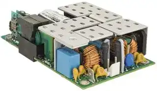
Illustrative purposes only

MVAC250-12F.
POWER SUPPLY, AC-DC, MEDICAL, 12V, 20.8A
⚠️ Reference pricing provided. In case of supply shortages, we will connect you with our trusted procurement partners to ensure your project's continuity.
- Manufacturer: MURATA POWER SOLUTIONS
- Product type: AC / DC Open Frame Power Supplies
- Product Range: MVAC Series
- No. of Outputs: 1 Output
- Input Voltage VAC: 90V AC to 264V AC
- Power Supply Approvals: Medical
- Power Supply Output Type: Fixed
- Output Current - Output 1: 20.8A
- Output Voltage - Output 1: 12V
- Power Rating (Forced Cooling): 250W @ 250LFM
- Power Rating (Convection Cooling): 170W
| Delivery and price | |
|---|---|
| Units per pack | 1 |
| Price | 119.42 € |
| Current stock | 10+ |
| Lead time | 7 days |
Datasheet

**MVAC250 Series** ## **www.murata-ps.com** 250W 3" x 5" High Density AC-DC Power Supply Converter ## **ORDERING GUIDE** |**ORDERING GUIDE**|**ORDERING GUIDE**|**ORDERING GUIDE**|**ORDERING GUIDE**|**ORDERING GUIDE**|**ORDERING GUIDE**| |---|---|---|---|---|---| |Model Number|Natural Convection Cooling|Forced Air Cooling|Main Output<br>(V1)|Main Output<br>Fan Output<br>(V2)|Aux Output<br>(V3)| |MVAC250-12F|170W|250W @ 250LFM|(V1)<br>12V|(V2)<br>12V|(V3)| |MVAC250-24F|||24V|12V|| |MVAC250-48F|||50V|12V|| |MVAC250-12AF|||12V|12V|5V| |MVAC250-12AFD*|||12V|12V|5V| |MVAC250-24AFD*|||24V|12V|5V| |MVAC250-48AFD*|||50V|12V|5V| |MVAC250-24AFT#|||24V|12V|5V| |MVAC-COVER|Optional cover kit assembly;see MVAC-COVER datasheet for details||||| ## **FEATURES** - IEC60601 Ed.3 medical (2 x MOPP Pri-Sec) EN60950 ITE safety approved * Refer to page 2 for current sharing model number MVAC250-xxAFD notes. - # CCC Certifi cation is not available for these models. - ~~__—s—_ai—iéwi(~~ 250W compact high density ~~“#aia#a’’“w“”’'‘(a(‘a(~~ aéa$®’” ~~,»D’WwWUWVXWXWAWwWCUCUTlTlTdT~~ **INPUT CHARACTERISTICS** ~~TT~~ 3" x 5" standard footprint Parameter |**INPUT CHARACTERISTICS**<br>~~,»D’WwWUWVXWXWAWwWCUCUTlTlTdTTT~~<br>~~Tree~~|**INPUT CHARACTERISTICS**<br>~~,»D’WwWUWVXWXWAWwWCUCUTlTlTdTTT~~<br>~~Tree~~|**INPUT CHARACTERISTICS**<br>~~,»D’WwWUWVXWXWAWwWCUCUTlTlTdTTT~~<br>~~Tree~~|**INPUT CHARACTERISTICS**<br>~~,»D’WwWUWVXWXWAWwWCUCUTlTlTdTTT~~<br>~~Tree~~|**INPUT CHARACTERISTICS**<br>~~,»D’WwWUWVXWXWAWwWCUCUTlTlTdTTT~~<br>~~Tree~~|**INPUT CHARACTERISTICS**<br>~~,»D’WwWUWVXWXWAWwWCUCUTlTlTdTTT~~<br>~~Tree~~| |---|---|---|---|---|---| |Parameter<br>~~,»D’WwWUWVXWXWAWwWCUCUTlTlTdT TT~~<br>~~Tree~~|Conditions<br>~~Tree~~|Min.<br>~~Tree~~|Typ.<br>~~Tree~~|Max.<br>~~Tree~~|Units<br>~~Tree~~| |Input Voltage Operating Range|Singlephase|90|115/230|264|Vac| ||DC|127||300|Vdc| |Input Frequency||47|50/60|63|Hz| |Turn-on Input Voltage|Input rising|80||90|Vac| |Turn-off Input Voltage|Input falling|70||80|| |Input Current|90Vac input,full load all outputs|||3.4|A| |No Load Input Power(MVAC250-xxAFD)7|(PS_ON = OFF,5V_Aux = 0A)|1.5||2.0|W| |Inrush Current|At 264Vac,at 25°C cold start||15||Apk| |Power Factor|At 230Vac,full load||0.96||| - High effi ciency up to 94% - Remote sense - Remote On/Off, Power OK (MVAC250-xxAFx) - Universal AC input with active PFC - Less than 1U high – 1.4" - Convection cooled operation up to 170W - Isolated 12V@1A fan output |**OUTPUT CHARACTERISTICS**<br>~~|~~|**OUTPUT CHARACTERISTICS**<br>~~|~~|**OUTPUT CHARACTERISTICS**<br>~~|~~|**OUTPUT CHARACTERISTICS**<br>~~|~~|**OUTPUT CHARACTERISTICS**<br>~~|~~|**OUTPUT CHARACTERISTICS**<br>~~|~~| |---|---|---|---|---|---| |Model Number<br>~~|~~|Main Output<br>Voltage (V1)<br>~~|~~|Load Current<br>~~|~~|Maximum Load<br>Capacitance<br>~~|~~|Line, Load, Cross<br>Regulation<br>~~|~~|Typical Effi ciency<br>@230Vac<br>~~|~~| |MVAC250-12F|Voltage (V1)<br>12V|0.4 to 20.8A|Capacitance<br>0 to 1500μF|Regulation<br>± 1%|93%| |MVAC250-24F<br>MVAC250-24AFT|24V|0.2 to 10.4A|0 to 300μF|± 1%|93%| |MVAC250-48F|50V|0.1 to 5.0A|0 to 82μF|± 1%|94%| |MVAC250-12AF|12V|0 to 20.8A|0 to 1500uF|± 1%|93%| |MVAC250-12AFD|12V @ 10.4A6|0 to 20.8A|0 to 1500μF|± 1.5%6|93%| |MVAC250-24AFD|24V @ 5.2A6|0 to 10.4A|0 to 300μF|± 1.5%6|93%| |MVAC250-48AFD|50V @ 2.5A6|0 to 5.0A|0 to 68μF|+3.0% / –1.5%6|94%| - Isolated 5V@2A standby/auxiliary output with models MVAC250-xxAFx - RoHS compliant - Active inrush protection - Current sharing option ## **DESCRIPTION** The MVAC250 series switching power supplies utilize advanced component and circuit technologies to deliver high effi ciency. Designed for medical, computing, communications, telecom and other OEM applications to satisfy 1U height design considerations, the MVAC250 Series measures only 3.0" x 5.0" x 1.40". All models offer universal AC input with active power factor correction (PFC) and compliance to worldwide safety and EMC standards. ## **Main Output Characteristics (all models)** Parameter Conditions Typ. Max. Units Transient Response[9] 50% load step, 1A/μsec slew rate ± 5 % Settling Time to 1% of Nominal 500 μsec Turn On Delay After application of input power 3 sec Output Voltage Rise Monotonic[5] 50 msec Output Holdup 120Vac/60Hz, full load 20 Temperature Coeffi cient 0.02 %/°C Ripple Voltage & Noise[1] 1 % Compensates for up to 0.5V of lead drop with Remote Sense remote sense connected. Protected against 500 mV short circuit and reverse connection. **Auxiliary Output Characteristics (varies by model)** Aux Output Line, Load, Cross Ripple Voltage & Auxiliary Output Load Current Load Capacitance Voltage[8] Regulation[3] Noise[1] ~~(5595959555353~~ Fan (V2) all models 12V 0 to 1A 0 to 220μF ~~eee~~ ± 10% 2% Aux (V3) – MVAC250-xxAFx 5V 0 to 2A 0 to 220μF ± 5% 1% **www.murata-ps.com/en/3d/acdc.html www.murata-ps.com/en/3d/acdc.html www.murata-ps.com/en/3d/acdc.html www.murata-ps.com/en/3d/acdc.html** in STEP, IGES, or **www.murata-ps.com/en/3d/acdc.html www.murata-ps.com/en/3d/acdc.html** aanefLy **Available now at www.murata-ps.com/en/3d/acdc.html** cy OAace For full details go to **www.murata-ps.com/rohs** **CB** Test Certifi cate and Test Report **www.murata-ps.com/support** **MVAC250.B02** Page 1 of 9 **MVAC250 Series** 250W 3" x 5" High Density AC-DC Power Supply Converter **==> picture [541 x 31] intentionally omitted <==** **----- Start of picture text -----**<br> ENVIRONMENTAL CHARACTERISTICS<br>Parameter Conditions Min. Typ. Max. Units<br>Storage Temperature Range -40 85<br>**----- End of picture text -----**<br> |**ENVIRONMENTAL CHARACTERISTICS**<br>Parameter<br>Storage Temperature Range|Conditions||Min.<br>-40|Typ.|Max.<br>85|Units| |---|---|---|---|---|---|---| |Operating Temperature Range|Seepower ratingcurves<br>Start up||-10<br>-20||70|°C| |Operating Humidity|Non-condensing||10||95|%| |OperatingAltitude|||-200||5000|m| |MTBF|Telcordia SR-332 M1C3 @25°C||474K|||Hours| |Shock|Operating,MIL-HBK-810E<br>Non-operating, MIL-HBK-810E||Complies<br>Complies|||| |Operational Vibration|IEC-68-2-27 standard||Complies to levels of IEC721-3-2|||| ||IEC60601-1 (Ed. 3) – CB Cert & Report|||||| |Safety – Medical Standards|ANSI/AAMI ES60601-1 (2005+ C1:2005+A2:10)|||||| |2 x MOPP (Primary-Secondary)|CAN/CSA 22.2 No. 60601-1 (2008) 3rd Edition|||||| ||EN60601-1:2006+CORR:2010|||||| ||UL60950-1:, 2nd Edition, 2011-12-19|||||| ||CSA22.2 No..60950-1-07, 2nd Edition, 2001-12.|||||| |Safety – ITE Standards|EN60950-1:2006+A11:2009/A1/2010/A12:2011|||||| ||IEC 60950 (ed.2), IEC60950 (ed.2);am1|||||| ||CE Marking per LVD|||||| |Warranty|2 years|||||| |Outside Dimensions|3.0" x 5.0" x 1.4" (76.2mm x 127mm x|35.6mm)||||| |Weight|MVAC250-xxF: 0.73 lbs (332.9g); MVAC250-xxAFD: 0.76 lbs (344.7g); MVAC250-xxAFT 0.78 lbs (352.7g)|||||| |**RESIDUAL RISK (PER ISO 14971 & IEC60601-1) FOR USER CONSIDERATION**|**RESIDUAL RISK (PER ISO 14971 & IEC60601-1) FOR USER CONSIDERATION**|**RESIDUAL RISK (PER ISO 14971 & IEC60601-1) FOR USER CONSIDERATION**||||| |---|---|---|---|---|---|---| |Fault Condition|Residual Risk|||||| |Complies|Contact your Murata salesperson for details|||||| |||||||| |**PROTECTION CHARACTERISTICS**||||||| |Parameter||Conditions|Min.|Typ.|Max.|Units| |Over Voltage Protection4||V1 (main output) latching<br>V3 (aux output: MVAC250-xxAFx) latching|110<br>5.5||125<br>7.5|%<br>V| |Over Current Protection4||V1, hiccup mode|110||130|%Amax| |Over Temperature Protection||Auto-recovery||Complies||| |Remote Sense Short Circuit Protection||||Complies||| |Remote Sense Reverse Connection Protection||||Complies||| |**ISOLATION CHARACTERISTICS**||||||| |Parameter||Conditions|Min.|Typ.|Max.|Units| |||Primaryto Chassis|1500|||| |Isolation||Primaryto Secondary (2xMOPP)<br>Secondaryto Chassis|4000<br>500|||Vac| |||Output to Output|500|||| |Earth Leakage Current (under single fault condition):<br>264Vac, 60Hz, 25°C<br>Earth Leakage Current (under normal conditions):<br>264Vac, 60Hz, 25°C||MVAC250-xxAFD<br>MVAC250-xxAF;-xxAFT<br>MVAC250-xxF<br>MVAC250-xxAFD<br>MVAC250-xxAF;-xxAFT<br>MVAC250-xxF||300<br>300<br>350<br>150<br>150<br>250||μA| **==> picture [542 x 32] intentionally omitted <==** **----- Start of picture text -----**<br> CURRENT SHARING OPTION – MVAC250-xxAFD ONLY<br>Model Number Description<br>Main Output: Current share is achieved using the droop method. Nominal output voltage is achieved at 50% load and output voltage increases/<br>**----- End of picture text -----**<br> |**CURRENT SHARING OPTION – MVAC250-xxAFD ONLY**|**CURRENT SHARING OPTION – MVAC250-xxAFD ONLY**| |---|---| |Model Number|Description| ||Main Output: Current share is achieved using the droop method. Nominal output voltage is achieved at 50% load and output voltage increases/| |MVAC250-12AFD<br>MVAC250-24AFD<br>MVAC250-48AFD|drops at a rate of:<br>• 48mv per amp for 12V output<br>• 192mV per amp for 24V output<br>• 800mV per amp for 50V output.<br>Startup of parallel power supplies is not internally synchronized. If more than 250W combined power is needed, start-up synchronization must be<br>provided by using a common PS_ON signal. To account for ±10% full load current sharing accuracy and the reduction in full load output voltage<br>due to droop, available output power must be derated by 15% when units are operated in parallel. Current sharing can be achieved with or without<br>remote sense connected to the common load. If ORing protection is desired, please contact Murata sales for external ORing FET board or external<br>ORing FET reference circuit design.<br>Aux (V3) output can be tied together for redundancy but total combined output power must not exceed 10W, external ORing devices must be used.<br>Fan(V2) canbe tied together for redundancy but totalcombined output power mustnot exceed12W, externalORing diodes canbe used.| **www.murata-ps.com/support** **MVAC250.B02** Page 2 of 9 **MVAC250 Series** 250W 3" x 5" High Density AC-DC Power Supply Converter **==> picture [541 x 25] intentionally omitted <==** **----- Start of picture text -----**<br> EMISSIONS AND IMMUNITY<br>Characteristic Standard Compliance<br>**----- End of picture text -----**<br> |**EMISSIONS AND IMMUNITY**|**EMISSIONS AND IMMUNITY**|**EMISSIONS AND IMMUNITY**| |---|---|---| |Characteristic|Standard|Compliance| |||| |Input Current Harmonics|IEC/EN 61000-3-2|Class A| |Voltage Fluctuation and Flicker|IEC/EN 61000-3-3|Complies| |Conducted Emissions|EN 55022|Class B| ||FCC Part 15|Class B| |ESD Immunity|IEC/EN 61000-4-2|Level 4,Criterion 2| |Radiated Field Immunity|IEC/EN 61000-4-3|Level 3,Criterion A| |Electrical Fast Transient Immunity|IEC/EN 61000-4-4|Level 4,Criterion A| |Surge Immunity|IEC/EN 61000-4-5|Level 3,Criterion A| |Radiated Field Conducted Immunity|IEC/EN 61000-4-6|Level 3,10V/m,Criterion A| |Magnetic Field Immunity|IEC/EN 61000-4-8|Level 3,Criterion A| |Voltage dips, interruptions|IEC/EN 61000-4-11|Level 3, Criterion B| ## **EMI CONSIDERATIONS** For optimum EMI performance, the power supply should be mounted to a metal plate grounded to all 4 mounting holes of the power supply. To comply with safety standards, this plate must be properly grounded to protective earth (see mechanical dimension notes). Pre-compliance testing has shown the stand-alone power supply to comply with EN55022 Class A radiated emissions. Class B radiated emissions are achievable with a metal enclosure. Radiated emission results vary with system enclosure and cable routing paths. ## **SAFETY CONSIDERATIONS** 1. This power supply is a component level power supply intended for use in Class I or Class II applications. Secondary ground traces need to be suitably isolated from primary ground traces when used in Class II applications. 2. When the power supply is used in Class II equipment, all ground traces and components connected to the primary side are considered primary for spacing and insulation considerations. **==> picture [542 x 26] intentionally omitted <==** **----- Start of picture text -----**<br> STATUS AND CONTROL SIGNALS – MVAC250-xxAFD ONLY<br>Parameter Models Conditions<br>**----- End of picture text -----**<br> |**STATUS AND CONTROL SIGNALS – MVAC250-xxAFD ONLY**|**STATUS AND CONTROL SIGNALS – MVAC250-xxAFD ONLY**|**STATUS AND CONTROL SIGNALS – MVAC250-xxAFD ONLY**| |---|---|---| |Parameter|Models|Conditions| |||| |PS_ON|All models except<br>as noted below.|This signal must be pulled low (sink current >2mA) to +5V_AUX_RTN to turn on the main and Fan (V2) output. The +5V_AUX output is independent<br>of the PS_ON signal and comes upautomaticallywhen the input AC or input DC voltage is applied within their specif ed operatingranges.| ||MVAC250-xxAFT|This pin is pulled high internally and so all three outputs (main, Fan output and +5V_AUX) come up automatically when the input AC or input DC voltage<br>is applied within their specif ed operatingranges. Pullingthispin low(sink current >2mA)to +5V_AUX_RTN will disable the main and fan outputs.| |PWR_OK|All models|Open collector logic goes high 50-200 msec after main output is in regulation; it goes low at least 6 msec before loss of regulation. Internal 10K pull<br>up to +5V_AUX is provided. Applications using PWR_OK signal should maintain a minimum load of 5W on the main or fan output.| 1. Noise and ripple is measured at an oscilloscope jack on the output, 20MHz bandwidth, and with - 0.1μF ceramic and 10μF aluminum electrolytic capacitors across the output pins. 2. Unless otherwise specifi ed all measurements are taken at 120Vac input and 25°C ambient temperature. 3. Fan (V2) regulation band applies from 0.1A to 1A load with a minimum of 10W load on the main (V1) output. 4. Fan (V2) has overvoltage protection (tracking V1) and short circuit protection. Overloading the Fan (V2) output can result in permanent damage to the unit. 5. 24V and 50V models may exhibit up to 5% turn on overshoot for loads less than 4% of full load. 6. See current sharing option section for droop characteristics. 7. No load Input power varies by model and by input line. Measurement is diffi cult to make due to burst mode operation. Please contact Murata sales if additional information is required. 8. All three output returns are isolated from each other (see isolation characteristics section); the returns may be tied together externally. 9. Load steps beginning from combined loads on the main and fan outputs of less than 5W may result in transient undershoots outside of the spec limits. ## **PART NUMBER STRUCTURE** **==> picture [542 x 157] intentionally omitted <==** **----- Start of picture text -----**<br> MV A x yyy - zz hhh<br>Modifi cation Code Options<br>Murata Manufacturing Corp.<br>A = Aux 5V Standby Voltage<br>F = Aux 12V Fan Output<br>D = Droop Current Share<br>Form Factor Outline T = Terminal Output Connector<br>A = 2x4", 3x5", or 4x7" R = Terminal Output Connector with Internal Or-ing Solution and Droop Current Share<br>Outline Detail Main Output Voltage (V)<br>B & D = 2x4" (12, 24, 28, or 50)<br>C = 3x5"<br>F = 4x7" Output Power (W)<br>(40, 65, 120, 160, 250, 400, or 750)<br>**----- End of picture text -----**<br> **www.murata-ps.com/support** **MVAC250.B02** Page 3 of 9 **MVAC250 Series** 250W 3" x 5" High Density AC-DC Power Supply Converter ## ~~OO~~ **PERFORMANCE DATA** MVAC250-12F Efficiency **==> picture [254 x 141] intentionally omitted <==** **----- Start of picture text -----**<br> 95<br>93<br>Pt | tet<br>91 P|) eeTE 90 Vin<br>89 TT 115 Vin<br>Piet 230 Vin<br>87<br>| i tt tt ye<br>85<br>83<br>81<br>Yi |||] yt<br>0 10 20 30 40 50 60 70 80 90 100<br>Load %<br>Efficiency %<br>**----- End of picture text -----**<br> MVAC250-24F Efficiency **==> picture [254 x 141] intentionally omitted <==** **----- Start of picture text -----**<br> 95<br>93<br>|| | | ee<br>91 Po hea [PE] 90 Vin<br>89 mn4s 115 Vin<br>230 Vin<br>87<br>fe _<br>85<br>83<br>81<br>pf] tT et ty<br>0 10 20 30 40 50 60 70 80 90 100<br>Load %<br>Efficiency %<br>**----- End of picture text -----**<br> MVAC250-48F Efficiency Inrush Current **==> picture [313 x 133] intentionally omitted <==** **----- Start of picture text -----**<br> 95<br>93<br>91 CCE} 90 Vin |<br>89 115 Vin<br>230 Vin<br>87<br>85 see n<br>83<br>pi | | tt ttt 1<br>81<br>| ¥ | | | | ty<br>0 10 20 30 40 50 60 70 80 90 100<br>Load %<br>Efficiency %<br>**----- End of picture text -----**<br> Time: 100 msec/div, Ch1: 500 V/div, Ch4: 20 A/div, Vin: 264 VAC, Ipk = 15.1 A AC applied at peak of sine wave **www.murata-ps.com/support** **MVAC250.B02** Page 4 of 9 **MVAC250 Series** 250W 3" x 5" High Density AC-DC Power Supply Converter ## ~~OO~~ **THERMAL CONSIDERATIONS** System thermal management is critical to the performance and reliability of the MVAC series power supplies. Performance derating curves are provided which can be used as a guideline for what can be achieved in a system confi guration with controlled airfl ow at various input voltage conditions. The air fl ow curves are generated using an AMCA 210-99 and ASHRAE 51-1999 compliant wind tunnel with heated inlet air and a controlled CFM providing a duct test section having a calculated average LFM. A correlation between the test setup and the actual system environment is paramount to understanding what can be achieved in an actual system. In a power supply of this density, cooling air moving both through the unit as well as around the unit strongly infl uences local temperatures. The wind tunnel test setup was constructed to produce a fl ow with a slight back pressure to induce both fl ow conditions by providing a small gap between the power supply and duct walls of 0.5" (13mm). The optimal and characterized airfl ow direction is from the input connector to the output connector (see diagram below). The P-Q fl ow curve for this test setup is also shown below. **P-Q CURVE, DUCTED FLOW** **==> picture [521 x 116] intentionally omitted <==** **----- Start of picture text -----**<br> 13mm [0.5in] all sides<br>Air Flow 0.0100<br>Power Supply<br>0.0075<br>*<br>0.0050<br>Ambient Temperature<br>Measurement 0.0025<br>Output Connector Input Connector 64mm [2.5in] 0.0000 oa 0 2.5 5 7.5 10 12.5 15 17.5 20 22.5<br>AIRFLOW-(CFM @ 0.075 lbs/cu ft air density)<br>Static Pressure (in. w.g.)<br>**----- End of picture text -----**<br> The natural convection data is obtained from a horizontally mounted power supply with un-obstructed fl ow at room temperature. At elevated temperature the power supply data is taken while it is surrounded by a large vented enclosure to minimize forced cross fl ows inherent in the elevated temperature test system. **==> picture [503 x 305] intentionally omitted <==** **----- Start of picture text -----**<br> Power Ra ng at 230Vac Power Ra ng at 120Vac<br>275 275<br>250 250<br>225 225<br>200 200<br>175 175<br>150 Nat Conv 150 Nat Conv<br>125 125<br>250LFM 250LFM<br>100 100<br>75 75<br>50 50<br>10 20 30 40 50 60 70 10 20 30 40 50 60 70<br>Ambient Temperature (Degrees C) Ambient Temperature (Degrees C)<br>Power Ra ng at 100Vac Power Ra ng at 90Vac<br>275 275<br>250 250<br>225 225<br>200 200<br>175 175<br>150 Nat Conv 150 Nat Conv<br>125 125<br>250LFM 250LFM<br>100 100<br>75 75<br>50 50<br>10 20 30 40 50 60 70 10 20 30 40 50 60 70<br>Ambient Temperature (Degrees C) Ambient Temperature (Degrees C)<br>s) s)<br>Output Power (Wa Output Power (Wa<br>s) s)<br>Output Power (Wa Output Power (Wa<br>**----- End of picture text -----**<br> **www.murata-ps.com/support** **MVAC250.B02** Page 5 of 9 **MVAC250 Series** 250W 3" x 5" High Density AC-DC Power Supply Converter ## **WIRING DIAGRAM FOR OUTPUT** **Dotted lines show optional remote sense connections. Optional remote sense lines can be attached to a load that is a distance away from the power supply to improve regulation at the load.** **==> picture [529 x 245] intentionally omitted <==** **----- Start of picture text -----**<br> +Remote Sense +Remote Sense<br>MVAC250-xxAFx J3 pin 5 +DC out MVAC250-xxF J3 pin 5 +DC out<br>J2 pins 1-6 J2 pins 1-6<br>Main Output Load Main Output Load<br>J2 pins 7-12 DC out return J2 pins 7-12 DC out return<br>J3 pin 6 -Remote Sense J3 pin 6 -Remote Sense<br>2K49 10K0<br>J3 pin 1 +5V_AUX<br>10 100 J3 pin 4 PS_ON<br>+5V logic circuitry<br>CTR~100 1N0 +5V_AUX >2mA<br>10K0<br>100 J3 pin 2<br>5 6 PWR_OK FET, BJT, wire<br>or switch (debounced )<br>2 to turn on +DC out<br>74LVC2G07 and +12V_fan<br>J3 pin 8 +5V_AUX_RTN<br>J3 pin 7 +12V_Fan J3 pin 7 +12V_Fan<br>Fan or Fan or<br>other load other load<br>J3 pin 3 +12V_FAN_RTN J3 pin 3 +12V_FAN_RTN<br>**----- End of picture text -----**<br> |**APPLICATION NOTE**|**APPLICATION NOTE**|**APPLICATION NOTE**| |---|---|---| |Document Number|Description|Link| |ACAN-42 MVAC Series|External ORing FET Reference Circuit|www.murata-ps.com/data/apnotes/acan-42.pdf| **www.murata-ps.com/support** **MVAC250.B02** Page 6 of 9 **MVAC250 Series** 250W 3" x 5" High Density AC-DC Power Supply Converter ## **MECHANICAL DIMENSIONS – MVAC250-xxF ONLY** **==> picture [330 x 185] intentionally omitted <==** **----- Start of picture text -----**<br> = [ MOUNTING GRIDS4.50 x 2.50 oe 114.30 A[4.500] 63.50 B[2.500]<br>oflf___erreC ) | 4.55 x 2.55 115.57 [4.550] 64.77 [2.550] 72<br>[ _—— — — = al l C Y “y<br>@| 7 6) J2 J2<br>®D ( &o yaznl PINI2 |= 65 1211 eee 7-121-6 +DC+DC_OUT_OUT_RTN<br>(l ai » | 4 10<br>9<br>2 8<br>1 7<br>o ooo P|sali i,PIN 8 J3<br>2 1 1 DO NOT USE<br>PRIMARY MTG3 4 3 2 DO NOT USE<br>HEATSINKNOTE3 /\ ! 86 57 34 +12VDO NOT USE_FAN_RTN<br>5 +REMOTE_SENSE<br>6 -REMOTE_SENSE<br>7 +12V_FAN<br>il a Ll | 8 DO NOT USE<br>ALITA ALL DIMENSIONS ARE IN MM [IN].<br>**----- End of picture text -----**<br> ## SAFETY CONSIDERATION NOTES: 1. Protective bonding conductor from the end product protective earthing terminal must be tied to TB1. For optimum EMI performance, while maintaining Class I safety isolation all 4 mounting holes must be tied to the end product protective earthing terminal. To maintain Class II safety isolation mounting holes MTG1 and MTG2 need to be isolated from protective earth and should use standoffs of non-conductive material. 2. This power supply requires mounting standoffs of minimum 6mm in height. If there is risk of chassis deformation or shorter standoff height is required, an appropriate insulator must be used under the power supply with adequate extension beyond the outline of the power supply. In all cases, the applicable safety standards must be applied to ensure proper creepage and clearance requirements are met. 3. The primary heatsink is considered a live primary circuit, and should not be touched. It is recommended that the primary heatsink be kept at least 3.5mm from chassis and 7mm from secondary circuits. In all cases, the applicable safety standards must be applied to ensure proper creepage and clearance requirements are met. 4. This product is subject to the following operating requirements and the Life and Safety Critical Application Sales Policy: Refer to: - http://www.murata ps.com/requirements/ 5. Used only in non-tropical conditions. 6. Double pole/neutral fusing. Dimensions: 3.0" x 5.0" x 1.4" (76.2mm x 127mm x 35.6mm) ## **INPUT/OUTPUT CONNECTOR AND SIGNAL SPECIFICATION AND MATING CONNECTORS – MVAC250-xxF ONLY** |**INPUT/OUTPUT CONNECTOR AND SIGNAL SPECIFICATION AND MATING CONNECTORS – MVAC250-xxF ONLY**|**INPUT/OUTPUT CONNECTOR AND SIGNAL SPECIFICATION AND MATING CONNECTORS – MVAC250-xxF ONLY**|**INPUT/OUTPUT CONNECTOR AND SIGNAL SPECIFICATION AND MATING CONNECTORS – MVAC250-xxF ONLY**|**INPUT/OUTPUT CONNECTOR AND SIGNAL SPECIFICATION AND MATING CONNECTORS – MVAC250-xxF ONLY**|**INPUT/OUTPUT CONNECTOR AND SIGNAL SPECIFICATION AND MATING CONNECTORS – MVAC250-xxF ONLY**| |---|---|---|---|---| |Connector|PIN|Description|MatingHousing|Crimpterminal/pins| |Input Connector J1 :<br>Molex 26-62-4030|1<br>AC Neutral|AC Neutral|Molex 0009930300|Molex 0008500105 (18-24 AWG)<br>Molex 0008500107(22-26 AWG)| ||3<br>AC Line|AC Line||| |Output Connector J2 :<br>Molex 39-28-1123|1,2,3,4,5,6<br>+DC_OUT|OUT|Molex 0039012125|Molex 0039000038| ||7,8,9,10,11,12<br>+DC_OUT|OUT_RTN||| |Output Connector J3:<br>Molex 90130-1108|1<br>DO NOT USE|DO NOT USE|Molex 0901420008|Molex 0901190109| ||2<br>DO NOT USE|DO NOT USE||| ||3<br>+12V_|_FAN_RTN||| ||4<br>DO NOT USE|DO NOT USE||| ||5<br>+ Remote Sense|+ Remote Sense||| ||6<br>– Remote Sense|– Remote Sense||| ||7<br>+12V_|_FAN||| ||8<br>DO NOT USE|DO NOT USE||| **www.murata-ps.com/support** **MVAC250.B02** Page 7 of 9 **MVAC250 Series** 250W 3" x 5" High Density AC-DC Power Supply Converter ## **MECHANICAL DIMENSIONS – MVAC250-xxAF & MVAC250-xxAFD** **==> picture [349 x 184] intentionally omitted <==** **----- Start of picture text -----**<br> MOUNTING GRIDS A B<br>L o a ieee “K Po 4.50 x 2.504.55 x 2.55 114.30 115.57 [4.550][4.500] 63.50 64.77 [2.550][2.500] F635 0.250]<br>of f i___ ere) Oo 52720.225}<br>@| o N) — Jo J2<br>6 12 1-6 +DC_OUT<br>i t al PINI2<br>5 11 7-12 +DC_OUT_RTN<br>ol© @)4 falec: J2 4 10 ee<br>3 9<br>1 ) OF J3 2 8<br>@e @ooo ae PIN [|] 1 7<br>o sac Jf]Ro J3PINS J3<br>2 1 1 +5V_AUX<br>PRIMARYHEATSINKNOTE3 /\ ! MTG3 468 357 234 +12VPWRPS_FAN__ONOK_RTN<br>5 +REMOTE_SENSE<br>6 -REMOTE_SENSE<br>aSS = = Fy 7 +12V_FAN<br>1 =a E 2m<br>8 +5V_AUX_RTN<br>| Ee ||<br>FLA<br>i altA[ im ALL DIMENSIONS ARE IN MM [IN].<br>**----- End of picture text -----**<br> ## SAFETY CONSIDERATION NOTES: 1. Protective bonding conductor from the end product protective earthing terminal must be tied to TB1. For optimum EMI performance, while maintaining Class I safety isolation all 4 mounting holes must be tied to the end product protective earthing terminal. To maintain Class II safety isolation mounting holes MTG1 and MTG2 need to be isolated from protective earth and should use standoffs of non-conductive material. 2. This power supply requires mounting standoffs of minimum 6mm in height. If there is risk of chassis deformation or shorter standoff height is required, an appropriate insulator must be used under the power supply with adequate extension beyond the outline of the power supply. In all cases,the applicable safety standards must be applied to ensure proper creepage and clearance requirements are met. 3. The primary heatsink is considered a live primary circuit, and should not be touched. It is recommended that the primary heatsink be kept at least 3.5mm from chassis and 7mm from secondary circuits. In all cases, the applicable safety standards must be applied to ensure proper creepage and clearance requirements are met. 4. This product is subject to the following operating requirements and the Life and Safety Critical Application Sales Policy: Refer to: - http://www.murata ps.com/requirements/ 5. Used only in non-tropical conditions 6. Double pole/neutral fusing. Dimensions: 3.0" x 5.0" x 1.4" (76.2mm x 127mm x 35.6mm) ## **INPUT/OUTPUT CONNECTOR AND SIGNAL SPECIFICATION AND MATING CONNECTORS – MVAC250-xxAF AND MVAC250-xxAFD MODELS** |**INPUT/OUTPUT CONNECTOR AND SIGNAL SPECIFICATION AND MATING CONNECTORS – MVAC250-xxAF AND MVAC250-xxAFD MODELS**|**INPUT/OUTPUT CONNECTOR AND SIGNAL SPECIFICATION AND MATING CONNECTORS – MVAC250-xxAF AND MVAC250-xxAFD MODELS**|**INPUT/OUTPUT CONNECTOR AND SIGNAL SPECIFICATION AND MATING CONNECTORS – MVAC250-xxAF AND MVAC250-xxAFD MODELS**|**INPUT/OUTPUT CONNECTOR AND SIGNAL SPECIFICATION AND MATING CONNECTORS – MVAC250-xxAF AND MVAC250-xxAFD MODELS**| |---|---|---|---| |Connector|PIN<br>Desc|escription<br>MatingHousing|Crimp terminal/pins| |Input Connector J1:<br>Molex 26-62-4030|1<br>ACNeutral|Molex 0009930300|Molex 0008500105 (18-24 AWG)<br>Molex 0008500107(22-26 AWG)| ||3<br>ACLine||| |Output Connector J2:<br>Molex 39-28-1123|1,2,3,4,5,6<br>+DC_OUT|Molex 0039012125|Molex 0039000038| ||7,8,9,10,11,12<br>+DC_OUT_RTN||| |Output Connector J3:<br>Molex 90130-1108|1<br>+5V_AUX|Molex 0901420008|Molex 0901190109| ||2<br>PWR_OK||| ||3<br>+12V_FAN_RTN||| ||4<br>PS_ON||| ||5<br>+ Remote Sense||| ||6<br>– Remote Sense||| ||7<br>+12V_FAN||| ||8<br>+5V_AUX_RTN||| **www.murata-ps.com/support** **MVAC250.B02** Page 8 of 9 **MVAC250 Series** 250W 3" x 5" High Density AC-DC Power Supply Converter ## **MECHANICAL DIMENSIONS – MVAC250-xxAFT** **==> picture [315 x 185] intentionally omitted <==** **----- Start of picture text -----**<br> +0.005 DIAMETER 07.40<br>a MOUNTING GRID A B<br>4.50 x 2.50 114.30 [4.500] 63.50 [ 2.500]<br>i SS seconpary Lo| 635 10.280]<br>4.55 x 2.55 115.57 [4.550] 64.77 [ 2.550]<br>!<br>ofli__ Fre (| NOTE 3/\<br>of [ ,<br>~ Swe n J<br>+DC_OUT<br>o| L oi)# TERMINALJ2 + [__J2p+2 [|( #6-32 +DC_OUT_RTN INSERTS ) _|<br>= GA TERMINAL- [| - |<br>AOA AN<br>J3 MVAC250-xxAFT<br>S © OC} g jv PIN 8 2 1 1 +5V_AUX<br>PRIMARYHEATSINK MTG3 4 3 2 PWR_OK<br>NOTE3 /\ ! 68 75 345 +REMOTE+12VPS_FAN_ON_SENSE_RTN<br>6 -REMOTE_SENSE<br>| | el ga 78 +5V+12V_AUX_FAN_RTN<br>**----- End of picture text -----**<br> ## SAFETY CONSIDERATION NOTES: 1. Protective bonding conductor from the end product protective earthing terminal must be tied to TB1. For optimum EMI performance, while maintaining Class I safety isolation all 4 mounting holes must be tied to the end product protective earthing terminal. To maintain Class II safety isolation mounting holes MTG1 and MTG2 need to be isolated from protective earth and should use standoffs of non-conductive material. 2. This power supply requires mounting standoffs of minimum 6mm in height. If there is risk of chassis deformation or shorter standoff height is required, an appropriate insulator must be used under the power supply with adequate extension beyond the outline of the power supply. In all cases,the applicable safety standards must be applied to ensure proper creepage and clearance requirements are met. 3. The primary heatsink is considered a live primary circuit, and should not be touched. It is recommended that the primary heatsink be kept at least 3.5mm from chassis and 7mm from secondary circuits. In all cases, the applicable safety standards must be applied to ensure proper creepage and clearance requirements are met. 4. This product is subject to the following operating requirements and the Life and Safety Critical Application Sales Policy: Refer to: - http://www.murata ps.com/requirements/ 5. Used only in non-tropical conditions 6. Double pole/neutral fusing. ## Dimensions: 3.0" x 5.0" x 1.4" (76.2mm x 127mm x 35.6mm) ## **INPUT/OUTPUT CONNECTOR AND SIGNAL SPECIFICATION AND MATING CONNECTORS – MVAC250-xxAFT** |Connector|Pin|Description|MatingHousing|CrimpTerminal/Pins| |---|---|---|---|---| |Input Connector J1:<br>Molex 26-62-4030|1<br>3|AC Neutral<br>AC Line|Molex 0009930300|Molex 0008500105 (18-24 AWG)<br>Molex 0008500107(22-26 AWG)| |Output Connector J2|+<br>–|+DC_OUT<br>+DC_OUT_RTN||| ||1|+5V_AUX||| ||2|PWR_OK||| ||3|+12V_FAN_RTN||| |Output Connector J3:<br>Molex 90130-1108|4<br>5|PS_ON<br>+ Remote Sense|Molex 0901420008|Molex 0901190109| ||6|– Remote Sense||| ||7|+12V_FAN||| ||8|+5V_AUX_RTN||| Murata Power Solutions, Inc. 11 Cabot Boulevard, Mansfi eld, MA 02048-1151 U.S.A. ISO 9001 and 14001 REGISTERED **This product is subject to the following operating requirements and the Life and Safety Critical Application Sales - Policy. Refer to: http://www.murata ps.com/requirements/** Murata Power Solutions, Inc. (“Murata”) makes no representation that the use of its products in the circuits described herein, or the use of other technical information contained herein, will not infringe upon existing or future patent rights. The descriptions contained herein do not imply the granting of licenses to make, use, or sell equipment constructed in accordance therewith. Buyer represents and agrees that it has all the necessary expertise to create and implement safeguards that anticipate dangerous consequences of failures, monitor failures and their consequences, lessen the likelihood of failures that might cause harm, and take appropriate remedial actions. Buyer will fully indemnify Murata, its affi liated companies, and its representatives against any damages arising out of the use of any Murata products in safety-critical applications. Specifi cations are subject to change without notice. _**© 2014 Murata Power Solutions, Inc.**_ **www.murata-ps.com/support** **MVAC250.B02** Page 9 of 9
Updated at February 9, 2023
About Novapart
Novapart is a B2B electronic component broker specialising in stock shortages and cost reduction. We source hard-to-find parts and identify compliant alternatives across a catalogue of 410,000+ components from 500+ manufacturers.
Learn more →Stock Shortage Specialist
When a component is unavailable, discontinued or has an unacceptable lead time, we tap into our network of vetted European and Asian distributors to source what you need — without compromising on quality or traceability.
Request a quote →Compliant Alternatives
We identify pin-to-pin, electrically equivalent substitutes that meet the same certifications (RoHS, AEC-Q100, REACH) as your original specification — validated against datasheets, not just part numbers. Often at a lower cost.
BOM Analysis service →