
Image not available
Illustrative purposes only

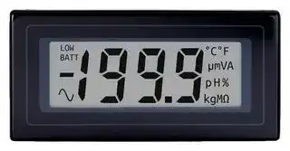
DPM 2000
Digital Panel Meter, DC Millivolts, 3-1/2Digits, 0-200mV, 15mm Digit Height, 14V
⚠️ Reference pricing provided. In case of supply shortages, we will connect you with our trusted procurement partners to ensure your project's continuity.
- Manufacturer: LASCAR
- Product type: Digital Panel Meters
- No. of Digits / Alpha:3-1/2; Meter Function:DC Voltage; Meter Range:0mV to 200mV; Digit Height:15mm; Panel Cutout Height:33mm; Panel Cutout Width:68mm; Supply Voltage Min:7.5V; Supp
- SVHC: No SVHC (07-Nov-2024)
- Meter Range: 0mV to 200mV
- Digit Height: 15mm
- Product Range: -
- Meter Function: DC Millivolts
- Panel Cutout Width: 68mm
- Supply Voltage Max: 14V
- Supply Voltage Min: 7.5V
- Panel Cutout Height: 33mm
- No. of Digits / Alpha: 3-1/2
- Operating Temperature Max: 50°C
- Operating Temperature Min: 0°C
| Delivery and price | |
|---|---|
| Units per pack | 10 |
| Price | 38.59 € |
| Current stock | 10+ |
| Lead time | 30 days |
Datasheet

DPM 2000

3½ Digit LCD Module

The DPM 2000 uses advanced components and construction techniques to provide an unrivalled combination of high performance, elegant appearance and low cost. The module uses a bandgap reference for extra temperature stability. For single rail operation, the DPM2000Sfeaturesabuilt-innegativerailgenerator,enablingthemetertomeasureasignalreferencedtoitsownpowersupply0V.

- **15mm (0.6“) Digit Height**

- **Programmable Decimal Points**

- **Auto-zero**

- **Auto-polarity**

- **200mV d.c. Full Scale Reading (F.S.R.)**

- **Single Rail Version**

## **SCALING**

Two resistors Ra and Rb may be fitted in order to alter **Stock Number** the full scale reading (F.S.R) of the meter - see table. **Standard Meter DPM 2000** The meter will need re-calibration. **Single Rail Version DPM 2000S Required F.S.R. Ra Rb** es **Specification Min.** es **Typ. Max. Unit** 2V Note 910k 100k Ss Accuracy (overall error) * 0.05 0.1 % (±1 count) 20V Note 1M 10k a Linearity ±1 count 200V Note 1M 1k Sample rate 3 samples/sec 2kV Note 1M 100R Operating temperature range 0 50 °C 200 µ A link 1k Temperature stability 30 ppm/°C 2mA link 100R es Supply voltage es DPM 2000 eees 7.5 eees 9 ee 14 V 20mA link 10R (V+ to V-) DPM 2000S 3.5 5 6.5 === 200mA link 1R a ~~Ss~~ Supply current DPM 2000SDPM 2000 500150 µ A **NOTE** pp Input leakage current (Vin = 0V) 1 10 pA Ensure that link 10 is open if fitting Ra. * To ensure maximum accuracy, re-calibrate periodically.

## **SAFETY**

To comply with the Low Voltage Directive (LVD 93/68/EEC), input voltages to the module’s pins must not exceed 60Vdc. If voltages to the measuring inputs do exceed 60Vdc, then fit scaling resistors externally to the module. The user must ensure that the incorporation of the DPM into the user’s equipmentconformstotherelevantsectionsofBSEN61010(SafetyRequirementsforElectricalEquipmentforMeasuring,ControlandLaboratoryUse).

**==> picture [218 x 11] intentionally omitted <==**

**----- Start of picture text -----**<br>
DIMENSIONS All dimensions in mm (inches)<br>**----- End of picture text -----**<br>


**==> picture [495 x 209] intentionally omitted <==**

**----- Start of picture text -----**<br>
72.0 (2.83) a b<br>enTe Tn Qa EG<br>6 ON BOARD<br>9 SOLDER LINKS<br>H5 11 4 2 7<br>8 12 14 1 3 SCALING RESISTORS<br>(wo 7 * O HM 5<br>13 RbRa<br>10<br>Display in TEST mode<br>67.5 (2.66)<br><—________________ 60.0 (2.36) Ø2.50(0.10) ae c d e f g<br>LMP a. 1.00 (0.04)<br>b. 9.00 (0.35)<br>c. 1.25 (0.05)<br>d. 5.50 (0.22)<br>e. 4.00 (0.16)<br>f. 0.50 (0.02)<br>in | g. 2.54 (0.10)<br>53.0 (2.09)<br>62.5 (2.46)<br>i) i oa)<br>(1.42)<br>36.0<br>+ - pH µ % V g °F °C A m Ω M K DP1 DP2 DP3 ~ : -<br>(1.28) (1.08) (0.75) (1.16) (1.16)<br>32.5 27.5 19.0 29.5 29.5 HI LO<br>TEST XB3 XDP -5V CLK XG3 V+ RBG REF- REF+ E3 BP AB POL REF REF COM IL IH V-<br>**----- End of picture text -----**<br>


**LASCAR ELECTRONICS INC. LASCAR ELECTRONICS (HK) LIMITED 3750 West 26th Street, FLAT C, 5/FL., LUCKY FTY. bldg., 63-65 HUNG TO ROAD Erie, PA 16506 USA KWUN TONG, KOWLOON, HONG KONG FAX: +1 (814) 838 8141 TEL: +852 2797 3219 FAX: +852 2343 6187 E-mail: us-sales@lascarelectronics.com E-mail: b4lascar@samsongroup.com.hk**

**LASCAR ELECTRONICS LTD. LASCAR ELECTRONICS INC. MODULE HOUSE, WHITEPARISH, 3750 West 26th Street, WILTSHIRE SP5 2SJ UK Erie, PA 16506 USA TEL: +44 (0)1794 884567 FAX: +44 (0)1794 884616 TEL: +1 (814) 835 0621 FAX: +1 (814) 838 8141 E-mail: sales@lascar.co.uk E-mail: us-sales@lascarelectronics.com**

## **PIN FUNCTIONS**

1. V- Negativepowersupplyconnection. 2. IH Positivemeasuringinput. Analogueinputsmustbenocloserthan1Vtoeitherthepositiveornegativesupply. Thenegative 3. IL Negativemeasuringinput. supplyofanS-typemeterisgeneratedinternallyandmirrorsthepositivesupplyvoltage. 4. COM ThegroundfortheanaloguesectionoftheA/Dconverter,heldactivelyat2.8V(nom.)belowV+. COMmustnotbeallowedtosink excessivecurrent(>100 µ A)byconnectingitdirectlytoahighervoltage.

5. REFLO Negativeinputforreferencevoltage.

6. REFHI Positiveinputforreferencevoltage(connectedviaLink1toREF+).

7. POL Drivefornegative(-)annunciator. InternallyconnectedviaLink11totheannunciator.

8,10,15,19 Outputsforautorangingapplications. 9. BP LCDbackplanedrivewaveform.

11. REF+ Positiveoutputfrominternalreference(connectedviaLink1toREFHI). 12. REFNegativeoutputfrominternalreference. MUSTbetiedtoasuitablegroundreturntobiasbandgap(normallyCOM). 13. RBG Ouputofbandgapreference(1.22Vnom). 14. V+ Positivepowersupplyconnection. 16. CLOCK Clockoutput.Maybeusedforsystemstimingorasaninputtooverridetheinternaloscillatorandcontrol thesamplerate. 17. -5V Outputfromnegativerailgeneratorcircuit(DPM2000Sonly). ThisisaninversionofV+. 18. XDP Connecttorequiredannunciators/DPs(seeSpecialNote-Annunciators). 20. TEST ConnecttoV+tomomentarilyturnonsegmentsasillustrated. ItshouldnotbeoperatedformorethanafewsecondsastheD.C. voltageappliedtotheLCDmay'burn'thedisplay. Thispinis5V(nom)belowV+andisthegroundforthedigitalsectionofthemeter. Itcanbeusedtopowerexternallogicuptoamaximumof1mA.

## **SPECIALNOTE-ANNUNCIATORS.**

The DPM annunciators (DPs, °C, etc.) can be displayed either by connecting to XDP or by applying a solder blob link to the XDP pads located under the annunciator input pads. However, as these annunciators are normally 'floating', under certain conditions they may appear when not wanted. To suppress unwanted annunciators, apply a solder blob to the backplane pads located in-between the annunciator input pads. If the annunciators are being switched, connect them via M Ω resistor to the BP (Pin 9), the annunciators will then operate normally when connected to XDP. Ensure that an annunciator is not connected directly to the XDP and BP at the same time.

Note - if suppressing POL (-) annunciator by direct connection to BP then Link 11 MUST be cut first.

**==> picture [209 x 104] intentionally omitted <==**

**----- Start of picture text -----**<br>
RIGHT WRONG<br>ANNUNCIATOR ANNUNCIATOR ANNUNCIATOR ANNUNCIATOR<br>BP BP<br>XDP XDP XDP XDP<br>Linktoeitherannunciator.BP or XDP DotoatnotthethelinkannunciatorsameBP time& XDP<br>**----- End of picture text -----**<br>


**==> picture [503 x 332] intentionally omitted <==**

**----- Start of picture text -----**<br>
VARIOUS OPERATING MODES<br>ON-BOARD LINKS: In order to quickly and easily change operating modes for different Normally Normally<br>meter has several on-board links. They are designed to be easily opened SHORTEDCut to OPENSolder to<br>(cut) or shorted (soldered). Do not connect more than one meter to the same power supply OPEN SHORT<br>meters cannot use the same signal ground. Taking any input beyond the power<br>supplyrailswilldamagethemeter.<br>V+ V+ V+<br>14 14 14<br>V+ V+ V+<br>2 2<br>+ IN HI + IN HI<br>+ 2 IN HI ±200mV - 3 IN LO 14V max. ±200mV - 3 IN LO<br>±200mV - 3 IN LO 7V min.<br>V- 0V V- V-<br>1 1vmin. 1 1<br>V- V- V-<br>Check Links 2, 3 & 4 are SHORTED. Check Links 3 & 4 are SHORTED. Check Links 3 & 4 are SHORTED.<br>Measuring a floating voltage source of 200mV Split supply operation (DPM 2000). Measuring a single ended input<br>full scale. referenced to supply (DPM 2000S).<br>V+ V+ V+<br>14 14 IIN 14<br>V+ + 2 IN HIV+ 2 IN HI V+<br>2 IN HI V1 - 3 IN LO 100K 13 REF BG<br>R<br>3 IN LO + 6 REF HI 6R2 5K SET 3 IN LO<br>R= [0.2] V2 - 5 REF LO ZERO 4 COM<br>IFSR V- V- V-<br>1 V- 1 V- IOUT 1 V-<br>Check Links 2, 3 & 4 are SHORTED. Check Link 1 is OPEN. Check Links 3 & 4 are SHORTED.<br>Measuring current (supply MUST be isolated). Measuring the ratio of two voltages. Measuring 4-20mA to read 0-999<br>Reading = 1000 V1/V2 (supply MUST be isolated).<br>50mV < V2 <200mV<br>V1< 2V2.<br>**----- End of picture text -----**<br>


## **VARIOUS OPERATING MODES**

ON-BOARD LINKS: In order to quickly and easily change operating modes for different applications, the meter has several on-board links. They are designed to be easily opened (cut) or shorted (soldered). Do not connect more than one meter to the same power supply if the meters cannot use the same signal ground. Taking any input beyond the power supplyrailswilldamagethemeter.

_**Specifications liable to change without prior warning**_

**August/2002 M.C.**

**Applies to DPM 2000/5**

**DPM 2000**

**Issue 4**
Updated at June 9, 2026
About Novapart
Novapart is a B2B electronic component broker specialising in stock shortages and cost reduction. We source hard-to-find parts and identify compliant alternatives across a catalogue of 410,000+ components from 500+ manufacturers.
Learn more →Stock Shortage Specialist
When a component is unavailable, discontinued or has an unacceptable lead time, we tap into our network of vetted European and Asian distributors to source what you need — without compromising on quality or traceability.
Request a quote →Compliant Alternatives
We identify pin-to-pin, electrically equivalent substitutes that meet the same certifications (RoHS, AEC-Q100, REACH) as your original specification — validated against datasheets, not just part numbers. Often at a lower cost.
BOM Analysis service →