


2611011024010
Bluetooth Module, BLE 5.1, 2 Mbps, -90 dBm, 1.8 to 3.8 V, -40 °C to 85 °C, Proteus-III-SPI Series
- Manufacturer: WURTH ELEKTRONIK
- Product type: Bluetooth Modules & Adaptors
- SVHC: No SVHC (25-Jun-2025)
- Interfaces: SPI
- Product Range: Proteus-III-SPI Series
- Certifications: -
- Bluetooth Class: Class 1
- Bluetooth Version: Bluetooth LE 5.1
- Supply Voltage Range: 1.8 V to 3.6 V
- Receiver Sensitivity Rx: -90 dBm
- Operating Temperature Range: -40 °C to 85 °C
| Delivery and price | |
|---|---|
| Units per pack | 250 |
| Price | 11.73 € |
| Current stock | 10+ |
| Lead time | 30 days |
**USER MANUAL** PROTEUS-III-SPI 2611011024010
VERSION 1.4
JUNE 28, 2023
## *******************
## **MUST READ**
## **Check for firmware updates**
Before using the product make sure you use the most recent firmware version, data sheet and user manual. This is especially important for Wireless Connectivity products that were not purchased directly from Würth Elektronik eiSos. A firmware update on these respective products may be required.
We strongly recommend to include in the customer system design, the possibility for a firmware update of the product.
**WIRELESS CONNECTIVITY & SENSORS** ~~OO~~ **User manual Proteus-III-SPI**
## **Revision history**
|Manual<br>version|FW<br>version|HW<br>version|Notes|Date|
|---|---|---|---|---|
|1.0|1.2.0|1.2|_•_ Initial release|February 2021|
|1.1|1.3.0|1.2|_•_ New features of firmware version 1.3.0.<br>Please refer to chapterFirmware<br>history.|July 2021|
|1.2|1.4.0|1.2|_•_ New features of firmware version 1.4.0.<br>Please refer to chapterFirmware<br>history.<br>_•_ Added overview of helpful application<br>notes|July 2022|
|1.3|1.4.0|1.2|_•_ Added radiation characterstics in<br>chapter16.2<br>_•_ Updated firmware update description in<br>chapter13.2.1<br>_•_ Added new radio certification for UKCA<br>in chapter22.6and India in<br>chapter22.10<br>_•_ Added chapter on radio compatibility to<br>other Proteus radio modules in<br>chapter5.13|May 2023|
|1.4|1.4.0|1.2|_•_ Added certificates in addition to the<br>required compliance statements in<br>chapterRegulatory compliance<br>information.|June 2023|
_⋆_ For firmware history see chapter Firmware history
Order code 2611011024010 Version 1.4, June 2023
1
_www.we-online.com/wcs_
**WIRELESS CONNECTIVITY & SENSORS** ~~OO~~ **User manual Proteus-III-SPI**
## **Abbreviations**
|Abbreviation|Name|Description|
|---|---|---|
|BTMAC||Bluetooth® conform MAC address of the module used<br>on the RF-interface.|
|CS|Checksum|Byte wise XOR combination of the preceding fields.|
|DSSS|Direct sequence<br>spread spectrum|Technique to spread a message on the radio|
|DTM|Direct test mode|Mode to test Bluetooth® specific RF settings.|
|EV (Board)|Evaluation (Board)|Proteus-III populated on motherboard with USB<br>interface for test and evaluation purpose.|
|FEC|Forward error<br>correction|Technique to correct received erroneous radio<br>messages|
|GAP|Generic Access<br>Profile|The GAP provides a basic level of functionality that all<br>Bluetooth® devices must implement.|
|I/O|Input/output|Pinout description.|
|LESC|Low energy<br>secure connection|Elliptic curve encryption method for Bluetooth® LE<br>encryption and authentication|
|LPM|Low power mode|Mode for efficient power consumption.|
|LRM|Long range mode|Radio mode with higher range and lower throughput.|
|MAC||MAC address of the module.|
|MTU|Maximum<br>transmission unit|Maximum packet size of the Bluetooth® connection.|
|Payload||The intended message in a frame / package.|
|RF|Radio frequency|Describes wireless transmission.|
|RSSI|Receive Signal<br>Strength Indicator|The RSSI indicates the strength of the RF signal. Its<br>value is always printed in two’s complement notation.|
|Soft device||Operating system used by the nRF52 chip.|
|SPI|Serial Peripheral<br>Interface|Allows the serial communication with the module.|
|UART|Universal<br>Asynchronous<br>Receiver<br>Transmitter|Allows the serial communication with the module.|
||User settings|Settings to configure the module. Any relation to a<br>specific entry in the user settings is marked in a<br>special font and can be found in chapter8.|
|[HEX] 0xhh|Hexadecimal|All numbers beginning with 0x are hexadecimal<br>numbers. All other numbers are decimal, unless<br>stated otherwise.|
Order code 2611011024010 Version 1.4, June 2023
2
_www.we-online.com/wcs_
**WIRELESS CONNECTIVITY & SENSORS** ~~OO~~ **User manual Proteus-III-SPI**
## **Contents**
|**Overview of helpful application notes**|**Overview of helpful application notes**|**Overview of helpful application notes**|||**11**|
|---|---|---|---|---|---|
|**1. Introduction**|||||**13**|
|1.1.|Operational description|. . . . .|.|. . . . . . . . . . . . . . . . . . . . . . . . .|13|
||1.1.1. Key features . .|. . . . .|.|. . . . . . . . . . . . . . . . . . . . . . . . .|14|
||1.1.2. Connectivity . .|. . . . .|.|. . . . . . . . . . . . . . . . . . . . . . . . .|15|
|1.2.|Block diagram . . . . . .|. . . . .|.|. . . . . . . . . . . . . . . . . . . . . . . . .|16|
|1.3.|Ordering information . .|. . . . .|.|. . . . . . . . . . . . . . . . . . . . . . . . .|16|
|**2. Electrical specifications**|||||**17**|
|2.1.|Recommended operating conditions|Recommended operating conditions . . . . . . . . . . . . . . . . . . . . . . . .|||17|
|2.2.|Absolute maximum ratings . . . .||.|. . . . . . . . . . . . . . . . . . . . . . . . .|17|
|2.3.|Power consumption . . .|. . . . .|.|. . . . . . . . . . . . . . . . . . . . . . . . .|18|
||2.3.1. Static . . . . . .|. . . . .|.|. . . . . . . . . . . . . . . . . . . . . . . . .|18|
||2.3.2. Dynamic . . . .|. . . . .|.|. . . . . . . . . . . . . . . . . . . . . . . . .|19|
|2.4.|Radio characteristics . .|. . . . .|.|. . . . . . . . . . . . . . . . . . . . . . . . .|21|
|2.5.|Pin characteristics<br>. . .|. . . . .|.|. . . . . . . . . . . . . . . . . . . . . . . . .|22|
|**3. Pinout**|||||**23**|
|**4. Quick start**|**Quick start**||||**26**|
|4.1.|Minimal pin connections|. . . . .|.|. . . . . . . . . . . . . . . . . . . . . . . . .|26|
|4.2.|Antenna connection<br>. .|. . . . .|.|. . . . . . . . . . . . . . . . . . . . . . . . .|28|
||4.2.1. On-board PCB antenna .||.|. . . . . . . . . . . . . . . . . . . . . . . . .|28|
||4.2.2. External antenna|. . . .|.|. . . . . . . . . . . . . . . . . . . . . . . . .|28|
|4.3.|Power up<br>. . . . . . . .|. . . . .|.|. . . . . . . . . . . . . . . . . . . . . . . . .|29|
|4.4.|Test the SPI interface . .|. . . . .|.|. . . . . . . . . . . . . . . . . . . . . . . . .|29|
|4.5.|Quickstart example . . .|. . . . .|.|. . . . . . . . . . . . . . . . . . . . . . . . .|30|
|**5. Functional description**|||||**33**|
|5.1.|Operation modes . . . .|. . . . .|.|. . . . . . . . . . . . . . . . . . . . . . . . .|33|
|5.2.|Radio module states . .|. . . . .|.|. . . . . . . . . . . . . . . . . . . . . . . . .|33|
|5.3.|State indication using the LED pins|State indication using the LED pins||. . . . . . . . . . . . . . . . . . . . . . . . .|35|
|5.4.|Sleep mode . . . . . . .|. . . . .|.|. . . . . . . . . . . . . . . . . . . . . . . . .|35|
|5.5.|Identification of a Proteus-III-SPI device on the radio . . . . . . . . . . . . . . .||||36|
|5.6.|Connection based data transmission, with or without security . . . . . . . . . .||||36|
||5.6.1. Further information for a secure connection setup . . . . . . . . . . . .||||37|
||5.6.1.1.<br>Just works mode . .||.|. . . . . . . . . . . . . . . . . . . . . . . . .|37|
||5.6.1.2.<br>StaticPasskey mode||.|. . . . . . . . . . . . . . . . . . . . . . . . .|40|
||5.6.1.3.<br>LescPasskey mode .||.|. . . . . . . . . . . . . . . . . . . . . . . . .|43|
||5.6.1.4.<br>LescNumComp mode|||. . . . . . . . . . . . . . . . . . . . . . . . .|46|
||5.6.1.5.<br>Bonding . .|. . . . .|.|. . . . . . . . . . . . . . . . . . . . . . . . .|49|
|5.7.|Unidirectional connectionless data transmission using Beacons||Unidirectional connectionless data transmission using Beacons . . . . . . . . .||53|
|5.8.|Energy-efficient distance estimation solutions|||Energy-efficient distance estimation solutions . . . . . . . . . . . . . . . . . . .|54|
|5.9.|Configure the module for low power consumption|||Configure the module for low power consumption . . . . . . . . . . . . . . . . .|54|
|5.10.|Start the direct test mode (DTM)|Start the direct test mode (DTM)|.|. . . . . . . . . . . . . . . . . . . . . . . . .|55|
|5.11.|Using the 2 MBit and LE Coded phy|||. . . . . . . . . . . . . . . . . . . . . . . .|57|
Order code 2611011024010 Version 1.4, June 2023
3 _www.we-online.com/wcs_
**WIRELESS CONNECTIVITY & SENSORS** ~~OO~~ **User manual Proteus-III-SPI**
||5.12.|Connection setup using LE Coded phy|Connection setup using LE Coded phy|Connection setup using LE Coded phy|Connection setup using LE Coded phy|. . . . . . . . . . . . . . . . . . . . . . .|57|
|---|---|---|---|---|---|---|---|
||5.13.|Radio compatibility to other Proteus devices||Radio compatibility to other Proteus devices . . . . . . . . . . . . . . . . . . . .|||60|
|**6. **|**Host connection**|**Host connection**|||||**61**|
||6.1.|Serial interface: SPI<br>. . . . . . .|.|.|.|. . . . . . . . . . . . . . . . . . . . . . .|61|
|||6.1.1. SPI communication details in command mode|||SPI communication details in command mode . . . . . . . . . . . . . .||62|
|||6.1.2. Shared WAKE_UP/SPI_INT pin . . . . . . . . . . . . . . . . . . . . . .|||||64|
|**7. **|**The command interface**||||||**66**|
||7.1.|Scan for other modules in range|.|.|.|. . . . . . . . . . . . . . . . . . . . . . .|67|
|||7.1.1. CMD_SCANSTART_REQ||.|.|. . . . . . . . . . . . . . . . . . . . . . .|67|
|||7.1.2. CMD_SCANSTOP_REQ|.|.|.|. . . . . . . . . . . . . . . . . . . . . . .|67|
|||7.1.3. CMD_GETDEVICES_REQ .||CMD_GETDEVICES_REQ .|.|. . . . . . . . . . . . . . . . . . . . . . .|68|
|||7.1.3.1.<br>Example 1 . . . . . .|.|.|.|. . . . . . . . . . . . . . . . . . . . . . .|69|
|||7.1.4. CMD_RSSI_IND<br>. . . .|.|.|.|. . . . . . . . . . . . . . . . . . . . . . .|69|
|||7.1.5. CMD_BEACON_RSP . .|.|.|.|. . . . . . . . . . . . . . . . . . . . . . .|70|
||7.2.|Setup connections . . . . . . . .|.|.|.|. . . . . . . . . . . . . . . . . . . . . . .|71|
|||7.2.1. CMD_CONNECT_REQ|.|.|.|. . . . . . . . . . . . . . . . . . . . . . .|71|
|||7.2.2. CMD_CONNECT_IND .|.|.|.|. . . . . . . . . . . . . . . . . . . . . . .|71|
|||7.2.3. CMD_SECURITY_IND .|.|.|.|. . . . . . . . . . . . . . . . . . . . . . .|72|
|||7.2.4. CMD_CHANNELOPEN_RSP||||. . . . . . . . . . . . . . . . . . . . . . .|72|
|||7.2.5. CMD_DISCONNECT_REQ|||.|. . . . . . . . . . . . . . . . . . . . . . .|72|
|||7.2.6. CMD_DISCONNECT_IND||.|.|. . . . . . . . . . . . . . . . . . . . . . .|73|
|||7.2.7. CMD_PHYUPDATE_REQ||.|.|. . . . . . . . . . . . . . . . . . . . . . .|73|
|||7.2.8. CMD_PHYUPDATE_IND|.|.|.|. . . . . . . . . . . . . . . . . . . . . . .|74|
|||7.2.9. CMD_PASSKEY_REQ .|.|.|.|. . . . . . . . . . . . . . . . . . . . . . .|74|
|||7.2.10.CMD_PASSKEY_IND . .|.|.|.|. . . . . . . . . . . . . . . . . . . . . . .|75|
|||7.2.11.CMD_DISPLAY_PASSKEY_IND . . . . . . . . . . . . . . . . . . . . . .|||||75|
|||7.2.12.CMD_NUMERIC_COMP_REQ||||. . . . . . . . . . . . . . . . . . . . . .|76|
|||7.2.13.CMD_GETBONDS_REQ|.|.|.|. . . . . . . . . . . . . . . . . . . . . . .|76|
|||7.2.13.1.<br>Example 1 . . . . . .|.|.|.|. . . . . . . . . . . . . . . . . . . . . . .|77|
|||7.2.14.CMD_DELETEBONDS_REQ||||. . . . . . . . . . . . . . . . . . . . . . .|77|
|||7.2.14.1.<br>Example 1 . . . . . .|.|.|.|. . . . . . . . . . . . . . . . . . . . . . .|78|
|||7.2.14.2.<br>Example 2 . . . . . .|.|.|.|. . . . . . . . . . . . . . . . . . . . . . .|78|
|||7.2.15.CMD_ALLOWUNBONDEDCONNECTIONS_REQ . . . . . . . . . . . .|||||79|
||7.3.|Transmit and receive data . . . .|.|.|.|. . . . . . . . . . . . . . . . . . . . . . .|80|
|||7.3.1. CMD_DATA_REQ . . . .|.|.|.|. . . . . . . . . . . . . . . . . . . . . . .|80|
|||7.3.2. CMD_TXCOMPLETE_RSP|||.|. . . . . . . . . . . . . . . . . . . . . . .|80|
|||7.3.3. CMD_DATA_IND<br>. . . .|.|.|.|. . . . . . . . . . . . . . . . . . . . . . .|81|
|||7.3.4. CMD_SETBEACON_REQ||.|.|. . . . . . . . . . . . . . . . . . . . . . .|81|
|||7.3.5. CMD_BEACON_IND . .|.|.|.|. . . . . . . . . . . . . . . . . . . . . . .|81|
||7.4.|Configuring the module and modifying the device settings . . . . . . . . . . . .|||||83|
|||7.4.1. CMD_SET_REQ<br>. . . .|.|.|.|. . . . . . . . . . . . . . . . . . . . . . .|83|
|||7.4.1.1.<br>Example 1 . . . . . .|.|.|.|. . . . . . . . . . . . . . . . . . . . . . .|84|
|||7.4.1.2.<br>Example 2 . . . . . .|.|.|.|. . . . . . . . . . . . . . . . . . . . . . .|84|
|||7.4.2. CMD_GET_REQ . . . .|.|.|.|. . . . . . . . . . . . . . . . . . . . . . .|85|
|||7.4.2.1.<br>Example 1 . . . . . .|.|.|.|. . . . . . . . . . . . . . . . . . . . . . .|85|
Order code 2611011024010 Version 1.4, June 2023
4
_www.we-online.com/wcs_
**WIRELESS CONNECTIVITY & SENSORS** ~~OO~~ **User manual Proteus-III-SPI**
||7.5.|Manage the device state . . . . . . . . . . . . . . . . . . . . . . . . . . . . . . .|86|
|---|---|---|---|
|||7.5.1. CMD_GETSTATE_REQ<br>. . . . . . . . . . . . . . . . . . . . . . . . . .|86|
|||7.5.1.1.<br>Example 1 . . . . . . . . . . . . . . . . . . . . . . . . . . . . . . . .|87|
|||7.5.2. CMD_RESET_REQ . . . . . . . . . . . . . . . . . . . . . . . . . . . . .|87|
|||7.5.3. CMD_SLEEP_REQ . . . . . . . . . . . . . . . . . . . . . . . . . . . . .|87|
|||7.5.4. CMD_SLEEP_IND<br>. . . . . . . . . . . . . . . . . . . . . . . . . . . . .|88|
|||7.5.5. CMD_FACTORYRESET_REQ . . . . . . . . . . . . . . . . . . . . . . .|88|
|||7.5.6. CMD_BOOTLOADER_REQ . . . . . . . . . . . . . . . . . . . . . . . .|89|
||7.6.|Run the Bluetooth test modes . . . . . . . . . . . . . . . . . . . . . . . . . . . .|91|
|||7.6.1. CMD_DTMSTART_REQ . . . . . . . . . . . . . . . . . . . . . . . . . .|91|
|||7.6.2. CMD_DTM_REQ . . . . . . . . . . . . . . . . . . . . . . . . . . . . . .|91|
|||7.6.2.1.<br>Example: Transmission, 16 times 0x0F, channel 0<br>. . . . . . . . .|93|
|||7.6.2.2.<br>Example: Receiver, channel 0 . . . . . . . . . . . . . . . . . . . . .|94|
|||7.6.2.3.<br>Example: Transmission, carrier test, channel 0<br>. . . . . . . . . . .|94|
|||7.6.2.4.<br>Example: Set TX power to -4 dBm . . . . . . . . . . . . . . . . . .|95|
|||7.6.2.5.<br>Example: Set PHY to 2 MBit mode . . . . . . . . . . . . . . . . . .|95|
||7.7.|Switching GPIOs by remote control . . . . . . . . . . . . . . . . . . . . . . . . .|96|
|||7.7.1. CMD_GPIO_LOCAL_WRITECONFIG_REQ . . . . . . . . . . . . . . .|96|
|||7.7.1.1.<br>Example: Configure two GPIOs to output high . . . . . . . . . . . .|97|
|||7.7.2. CMD_GPIO_LOCAL_READCONFIG_REQ<br>. . . . . . . . . . . . . . .|99|
|||7.7.2.1.<br>Example: Read the current GPIO configuration . . . . . . . . . . .|100|
|||7.7.3. CMD_GPIO_REMOTE_WRITECONFIG_REQ . . . . . . . . . . . . . .|101|
|||7.7.3.1.<br>Example: Configure two GPIOs of the connected remote device||
|||to output high . . . . . . . . . . . . . . . . . . . . . . . . . . . . . .|102|
|||7.7.4. CMD_GPIO_REMOTE_READCONFIG_REQ . . . . . . . . . . . . . .|104|
|||7.7.4.1.<br>Example: Read the current GPIO configuration of the connected||
|||remote device . . . . . . . . . . . . . . . . . . . . . . . . . . . . . .|105|
|||7.7.5. CMD_GPIO_REMOTE_WRITE_REQ . . . . . . . . . . . . . . . . . . .|106|
|||7.7.5.1.<br>Example: Set a remote output GPIO to low<br>. . . . . . . . . . . . .|107|
|||7.7.6. CMD_GPIO_REMOTE_READ_REQ . . . . . . . . . . . . . . . . . . .|108|
|||7.7.6.1.<br>Example: Read the values of remote GPIOs . . . . . . . . . . . . .|109|
|||7.7.7. CMD_GPIO_LOCAL_WRITE_REQ . . . . . . . . . . . . . . . . . . . .|110|
|||7.7.7.1.<br>Example: Set a local output GPIO to low . . . . . . . . . . . . . . .|111|
|||7.7.8. CMD_GPIO_LOCAL_READ_REQ<br>. . . . . . . . . . . . . . . . . . . .|112|
|||7.7.8.1.<br>Example: Read the values of local GPIOs . . . . . . . . . . . . . .|113|
|||7.7.9. CMD_GPIO_REMOTE_WRITECONFIG_IND . . . . . . . . . . . . . .|114|
|||7.7.9.1.<br>Example: Two GPIOs have been configured by the connected re-||
|||mote device to output high . . . . . . . . . . . . . . . . . . . . . . .|114|
|||7.7.10.CMD_GPIO_REMOTE_WRITE_IND . . . . . . . . . . . . . . . . . . .|115|
|||7.7.10.1.<br>Example: GPIOs have been written via remote access . . . . . . .|115|
|||7.7.11.CMD_GPIO_LOCAL_WRITE_IND<br>. . . . . . . . . . . . . . . . . . . .|116|
|||7.7.11.1.<br>Example: GPIOs of the remote device have been written by its||
|||local host<br>. . . . . . . . . . . . . . . . . . . . . . . . . . . . . . . .|116|
||7.8.|Message overview . . . . . . . . . . . . . . . . . . . . . . . . . . . . . . . . . .|117|
|**8. **|**UserSettings - Module configuration values**||**121**|
||8.1.|FS_DeviceInfo: Read the chip type and OS version . . . . . . . . . . . . . . . .|121|
|||8.1.1. Example 1 . . . . . . . . . . . . . . . . . . . . . . . . . . . . . . . . . .|122|
Order code 2611011024010 Version 1.4, June 2023
5 _www.we-online.com/wcs_
**WIRELESS CONNECTIVITY & SENSORS** ~~OO~~ **User manual Proteus-III-SPI**
|8.2.|FS_FWVersion: Read the firmware version|. . . . . . . . . . . . . . . . . . . . 123|
|---|---|---|
||8.2.1. Example 1 . . . . . . . . . . . . . .|. . . . . . . . . . . . . . . . . . . . 123|
|8.3.|FS_MAC: Read the MAC address . . . . . .|. . . . . . . . . . . . . . . . . . . . 124|
||8.3.1. Example 1 . . . . . . . . . . . . . .|. . . . . . . . . . . . . . . . . . . . 124|
|8.4.|FS_BTMAC: Read the Bluetooth conform MAC address . . . . . . . . . . . . . 125||
||8.4.1. Example 1 . . . . . . . . . . . . . .|. . . . . . . . . . . . . . . . . . . . 125|
|8.5.|FS_SerialNumber: Read the serial number of the module . . . . . . . . . . . . 126||
||8.5.1. Example 1 . . . . . . . . . . . . . .|. . . . . . . . . . . . . . . . . . . . 126|
|8.6.|RF_DeviceName: Modify the device name .|. . . . . . . . . . . . . . . . . . . . 127|
||8.6.1. Example 1 . . . . . . . . . . . . . .|. . . . . . . . . . . . . . . . . . . . 127|
||8.6.2. Example 2 . . . . . . . . . . . . . .|. . . . . . . . . . . . . . . . . . . . 127|
|8.7.|RF_StaticPasskey: Modify the static passkey|. . . . . . . . . . . . . . . . . . . 129|
||8.7.1. Example 1 . . . . . . . . . . . . . .|. . . . . . . . . . . . . . . . . . . . 129|
||8.7.2. Example 2 . . . . . . . . . . . . . .|. . . . . . . . . . . . . . . . . . . . 129|
|8.8.|RF_SecFlags: Modify the security settings .|. . . . . . . . . . . . . . . . . . . . 130|
||8.8.1. Example 1 . . . . . . . . . . . . . .|. . . . . . . . . . . . . . . . . . . . 131|
||8.8.2. Example 2 . . . . . . . . . . . . . .|. . . . . . . . . . . . . . . . . . . . 132|
|8.9.|RF_ScanFlags: Modify the scan behavior .|. . . . . . . . . . . . . . . . . . . . 133|
||8.9.1. Example 1 . . . . . . . . . . . . . .|. . . . . . . . . . . . . . . . . . . . 133|
||8.9.2. Example 2 . . . . . . . . . . . . . .|. . . . . . . . . . . . . . . . . . . . 133|
|8.10.|RF_BeaconFlags: Interpret the advertising data . . . . . . . . . . . . . . . . . . 135||
||8.10.1.Example 1 . . . . . . . . . . . . . .|. . . . . . . . . . . . . . . . . . . . 135|
||8.10.2.Example 2 . . . . . . . . . . . . . .|. . . . . . . . . . . . . . . . . . . . 136|
|8.11.|RF_AdvertisingTimeout: Modify the advertising timeout<br>. . . . . . . . . . . . . 137||
||8.11.1.Example 1 . . . . . . . . . . . . . .|. . . . . . . . . . . . . . . . . . . . 137|
||8.11.2.Example 2 . . . . . . . . . . . . . .|. . . . . . . . . . . . . . . . . . . . 137|
|8.12.|RF_AdvertisingFlags: Configure the advertising packet . . . . . . . . . . . . . . 138||
||8.12.1.Example 1 . . . . . . . . . . . . . .|. . . . . . . . . . . . . . . . . . . . 138|
||8.12.2.Example 2 . . . . . . . . . . . . . .|. . . . . . . . . . . . . . . . . . . . 139|
|8.13.|RF_ScanFactor: Modify the scan factor<br>. .|. . . . . . . . . . . . . . . . . . . . 140|
||8.13.1.Example 1 . . . . . . . . . . . . . .|. . . . . . . . . . . . . . . . . . . . 140|
||8.13.2.Example 2 . . . . . . . . . . . . . .|. . . . . . . . . . . . . . . . . . . . 140|
|8.14.|RF_ScanTiming: Modify the scan timing . .|. . . . . . . . . . . . . . . . . . . . 141|
||8.14.1.Example 1 . . . . . . . . . . . . . .|. . . . . . . . . . . . . . . . . . . . 142|
||8.14.2.Example 2 . . . . . . . . . . . . . .|. . . . . . . . . . . . . . . . . . . . 142|
|8.15.|RF_ConnectionTiming: Modify the connection timing . . . . . . . . . . . . . . . 143||
||8.15.1.Example 1 . . . . . . . . . . . . . .|. . . . . . . . . . . . . . . . . . . . 144|
||8.15.2.Example 2 . . . . . . . . . . . . . .|. . . . . . . . . . . . . . . . . . . . 144|
|8.16.|RF_TXPower: Modify the output power . . .|. . . . . . . . . . . . . . . . . . . . 146|
||8.16.1.Example 1 . . . . . . . . . . . . . .|. . . . . . . . . . . . . . . . . . . . 146|
||8.16.2.Example 2 . . . . . . . . . . . . . .|. . . . . . . . . . . . . . . . . . . . 146|
|8.17.|RF_SPPBaseUUID: Configure the SPP base UUID . . . . . . . . . . . . . . . . 148||
||8.17.1.Example 1 . . . . . . . . . . . . . .|. . . . . . . . . . . . . . . . . . . . 148|
||8.17.2.Example 2 . . . . . . . . . . . . . .|. . . . . . . . . . . . . . . . . . . . 148|
|8.18.|RF_SPPServiceUUID: Configure the SPP service UUID . . . . . . . . . . . . . 149||
||8.18.1.Example 1 . . . . . . . . . . . . . .|. . . . . . . . . . . . . . . . . . . . 149|
||8.18.2.Example 2 . . . . . . . . . . . . . .|. . . . . . . . . . . . . . . . . . . . 149|
Order code 2611011024010 Version 1.4, June 2023
6
_www.we-online.com/wcs_
**WIRELESS CONNECTIVITY & SENSORS** ~~OO~~ **User manual Proteus-III-SPI**
|8.19.|RF_SPPRXUUID: Configure the SPP RX UUID . . . . . . . . . . . . . . . . . . 150|
|---|---|
||8.19.1.Example 1 . . . . . . . . . . . . . . . . . . . . . . . . . . . . . . . . . . 150|
||8.19.2.Example 2 . . . . . . . . . . . . . . . . . . . . . . . . . . . . . . . . . . 150|
|8.20.|RF_SPPTXUUID: Configure the SPP TX UUID . . . . . . . . . . . . . . . . . . 151|
||8.20.1.Example 1 . . . . . . . . . . . . . . . . . . . . . . . . . . . . . . . . . . 151|
||8.20.2.Example 2 . . . . . . . . . . . . . . . . . . . . . . . . . . . . . . . . . . 151|
|8.21.|RF_Appearance: Configure the appearance of the device . . . . . . . . . . . . 152|
||8.21.1.Example 1 . . . . . . . . . . . . . . . . . . . . . . . . . . . . . . . . . . 152|
||8.21.2.Example 2 . . . . . . . . . . . . . . . . . . . . . . . . . . . . . . . . . . 152|
|8.22.|SPI_ConfigIndex: Modify the SPI mode<br>. . . . . . . . . . . . . . . . . . . . . . 153|
||8.22.1.Example 1 . . . . . . . . . . . . . . . . . . . . . . . . . . . . . . . . . . 153|
||8.22.2.Example 2 . . . . . . . . . . . . . . . . . . . . . . . . . . . . . . . . . . 153|
|8.23.|CFG_Flags: Configure the module . . . . . . . . . . . . . . . . . . . . . . . . . 155|
||8.23.1.Example 1 . . . . . . . . . . . . . . . . . . . . . . . . . . . . . . . . . . 155|
||8.23.2.Example 2 . . . . . . . . . . . . . . . . . . . . . . . . . . . . . . . . . . 155|
|8.24.|DIS_ManufacturerName: Configure the manufacturer name . . . . . . . . . . . 157|
||8.24.1.Example 1 . . . . . . . . . . . . . . . . . . . . . . . . . . . . . . . . . . 157|
||8.24.2.Example 2 . . . . . . . . . . . . . . . . . . . . . . . . . . . . . . . . . . 157|
|8.25.|DIS_ModelNumber: Configure the model number . . . . . . . . . . . . . . . . . 159|
||8.25.1.Example 1 . . . . . . . . . . . . . . . . . . . . . . . . . . . . . . . . . . 159|
||8.25.2.Example 2 . . . . . . . . . . . . . . . . . . . . . . . . . . . . . . . . . . 159|
|8.26.|DIS_SerialNumber: Configure the serial number<br>. . . . . . . . . . . . . . . . . 161|
||8.26.1.Example 1 . . . . . . . . . . . . . . . . . . . . . . . . . . . . . . . . . . 161|
||8.26.2.Example 2 . . . . . . . . . . . . . . . . . . . . . . . . . . . . . . . . . . 161|
|8.27.|DIS_HWVersion: Configure the HW version . . . . . . . . . . . . . . . . . . . . 163|
||8.27.1.Example 1 . . . . . . . . . . . . . . . . . . . . . . . . . . . . . . . . . . 163|
||8.27.2.Example 2 . . . . . . . . . . . . . . . . . . . . . . . . . . . . . . . . . . 163|
|8.28.|DIS_SWVersion: Configure the SW version . . . . . . . . . . . . . . . . . . . . 165|
||8.28.1.Example 1 . . . . . . . . . . . . . . . . . . . . . . . . . . . . . . . . . . 165|
||8.28.2.Example 2 . . . . . . . . . . . . . . . . . . . . . . . . . . . . . . . . . . 165|
|8.29.|DIS_Flags: Configure the device information service . . . . . . . . . . . . . . . 167|
||8.29.1.Example 1 . . . . . . . . . . . . . . . . . . . . . . . . . . . . . . . . . . 167|
||8.29.2.Example 2 . . . . . . . . . . . . . . . . . . . . . . . . . . . . . . . . . . 167|
|**9. Timing parameters**<br>**171**||
|9.1.|Reset and sleep<br>. . . . . . . . . . . . . . . . . . . . . . . . . . . . . . . . . . . 171|
|9.2.|Bluetooth LE timing parameters . . . . . . . . . . . . . . . . . . . . . . . . . . . 171|
|9.3.|Connection establishment . . . . . . . . . . . . . . . . . . . . . . . . . . . . . . 171|
|9.4.|Connection based data transmission . . . . . . . . . . . . . . . . . . . . . . . . 172|
||9.4.1. Maximum data throughput . . . . . . . . . . . . . . . . . . . . . . . . . 173|
|**10.Remote GPIO control**<br>**175**||
|10.1.|PWM . . . . . . . . . . . . . . . . . . . . . . . . . . . . . . . . . . . . . . . . . . 180|
|10.2.|Supported GPIO_IDs for remote and local control . . . . . . . . . . . . . . . . . 181|
|**11.Customizing the Proteus-III-SPI**<br>**182**||
|11.1.|DIS - Device information service<br>. . . . . . . . . . . . . . . . . . . . . . . . . . 182|
|11.2.|UUID . . . . . . . . . . . . . . . . . . . . . . . . . . . . . . . . . . . . . . . . . . 182|
Order code 2611011024010 Version 1.4, June 2023
7 _www.we-online.com/wcs_
**WIRELESS CONNECTIVITY & SENSORS** ~~OO~~ **User manual Proteus-III-SPI**
|11.3. Appearance . . . . . . . . . . . . . . . . . . . . . . . . . . .|. . . . . . . . . . . 183|
|---|---|
|**12.Custom firmware**|**184**|
|12.1. Custom configuration of standard firmware<br>. . . . . . . . .|. . . . . . . . . . . 184|
|12.2. Customer specific firmware . . . . . . . . . . . . . . . . . .|. . . . . . . . . . . 184|
|12.3. Customer firmware . . . . . . . . . . . . . . . . . . . . . . .|. . . . . . . . . . . 184|
|12.4. Contact for firmware requests . . . . . . . . . . . . . . . . .|. . . . . . . . . . . 185|
|**13.Firmware updates**|**186**|
|13.1. Firmware flashing using the production interface<br>. . . . . .|. . . . . . . . . . . 186|
|13.2. Firmware update using the Proteus-III-SPI OTA bootloader|. . . . . . . . . . . 186|
|13.2.1.Firmware update steps using the nRF Device Firmware Update app . . 188||
|**14.Firmware history**|**189**|
|**15.Design in guide**|**190**|
|15.1. Advice for schematic and layout . . . . . . . . . . . . . . . .|. . . . . . . . . . . 190|
|15.2. Dimensioning of the micro strip antenna line . . . . . . . . .|. . . . . . . . . . . 192|
|15.3. Antenna solutions<br>. . . . . . . . . . . . . . . . . . . . . . .|. . . . . . . . . . . 193|
|15.3.1.Wire antenna<br>. . . . . . . . . . . . . . . . . . . . .|. . . . . . . . . . . 194|
|15.3.2.Chip antenna<br>. . . . . . . . . . . . . . . . . . . . .|. . . . . . . . . . . 194|
|15.3.3.PCB antenna<br>. . . . . . . . . . . . . . . . . . . . .|. . . . . . . . . . . 194|
|15.3.4.Antennas provided by Würth Elektronik eiSos . . .|. . . . . . . . . . . 195|
|15.3.4.1.<br>2600130021 - Himalia - 2.4 GHz dipole antenna|. . . . . . . . . . 195|
|**16.Reference design**|**196**|
|16.1. Mini EV-Board . . . . . . . . . . . . . . . . . . . . . . . . . .|. . . . . . . . . . . 197|
|16.2. Radiation characteristic of the module’s internal antenna . .|. . . . . . . . . . . 199|
|16.3. Trace design<br>. . . . . . . . . . . . . . . . . . . . . . . . . .|. . . . . . . . . . . 200|
|**17.Manufacturing information**|**204**|
|17.1. Moisture sensitivity level . . . . . . . . . . . . . . . . . . . .|. . . . . . . . . . . 204|
|17.2. Soldering<br>. . . . . . . . . . . . . . . . . . . . . . . . . . . .|. . . . . . . . . . . 204|
|17.2.1.Reflow soldering<br>. . . . . . . . . . . . . . . . . . .|. . . . . . . . . . . 204|
|17.2.2.Cleaning . . . . . . . . . . . . . . . . . . . . . . . .|. . . . . . . . . . . 206|
|17.2.3.Potting and coating . . . . . . . . . . . . . . . . . .|. . . . . . . . . . . 206|
|17.2.4.Other notations . . . . . . . . . . . . . . . . . . . .|. . . . . . . . . . . 206|
|17.3. ESD handling . . . . . . . . . . . . . . . . . . . . . . . . . .|. . . . . . . . . . . 207|
|17.4. Safety recommendations . . . . . . . . . . . . . . . . . . . .|. . . . . . . . . . . 207|
|**18.Physical specifications**|**209**|
|18.1. Dimensions . . . . . . . . . . . . . . . . . . . . . . . . . . .|. . . . . . . . . . . 209|
|18.2. Weight . . . . . . . . . . . . . . . . . . . . . . . . . . . . . .|. . . . . . . . . . . 209|
|18.3. Module drawing . . . . . . . . . . . . . . . . . . . . . . . . .|. . . . . . . . . . . 210|
|18.4. Footprint WE-FP-4+<br>. . . . . . . . . . . . . . . . . . . . . .|. . . . . . . . . . . 211|
|18.5. Antenna free area<br>. . . . . . . . . . . . . . . . . . . . . . .|. . . . . . . . . . . 211|
|**19.Marking**|**212**|
|19.1. Lot number<br>. . . . . . . . . . . . . . . . . . . . . . . . . . .|. . . . . . . . . . . 212|
Order code 2611011024010 Version 1.4, June 2023
8 _www.we-online.com/wcs_
**WIRELESS CONNECTIVITY & SENSORS** ~~OO~~ **User manual Proteus-III-SPI**
|19.2. General labeling information .|.|. . . . . . . . . . . . . . . . . . . . . . . . . . . 213|
|---|---|---|
|**20.Information for explosion protection**||**214**|
|**21.Bluetooth SIG listing/qualification**||**215**|
|**22.Regulatory compliance information**||**216**|
|22.1. Important notice EU<br>. . . . .|.|. . . . . . . . . . . . . . . . . . . . . . . . . . . 216|
|22.2. Important notice FCC<br>. . . .|.|. . . . . . . . . . . . . . . . . . . . . . . . . . . 216|
|22.3. Conformity assessment of the final product<br>. . . . . . . . . . . . . . . . . . . . 216|||
|22.4. Exemption clause . . . . . . .|.|. . . . . . . . . . . . . . . . . . . . . . . . . . . 216|
|22.5. EU Declaration of conformity|.|. . . . . . . . . . . . . . . . . . . . . . . . . . . 217|
|22.6. UK Declaration of conformity|.|. . . . . . . . . . . . . . . . . . . . . . . . . . . 218|
|22.7. FCC Compliance Statement (US) . . . . . . . . . . . . . . . . . . . . . . . . . . 219|||
|22.7.1.FCC certificate<br>. . .|.|. . . . . . . . . . . . . . . . . . . . . . . . . . . 219|
|22.8. IC Compliance Statement (Canada)<br>. . . . . . . . . . . . . . . . . . . . . . . . 220|||
|22.8.1.IC certificate . . . . .|.|. . . . . . . . . . . . . . . . . . . . . . . . . . . 220|
|22.9. FCC and IC requirements to OEM integrators . . . . . . . . . . . . . . . . . . . 221|||
|22.9.1.Pre-certified antennas||. . . . . . . . . . . . . . . . . . . . . . . . . . . 222|
|22.10. ETA-WPC (India) . . . . . . .|.|. . . . . . . . . . . . . . . . . . . . . . . . . . . 223|
|22.10.1.ETA-WPC certificate|.|. . . . . . . . . . . . . . . . . . . . . . . . . . . 223|
|**23.References**||**225**|
|**24.Important notes**||**226**|
|24.1. General customer responsibility||. . . . . . . . . . . . . . . . . . . . . . . . . . . 226|
|24.2. Customer responsibility related||to specific, in particular safety-relevant appli-|
|cations . . . . . . . . . . . . .|.|. . . . . . . . . . . . . . . . . . . . . . . . . . . 226|
|24.3. Best care and attention<br>. . .|.|. . . . . . . . . . . . . . . . . . . . . . . . . . . 226|
|24.4. Customer support for product specifications . . . . . . . . . . . . . . . . . . . . 226|||
|24.5. Product improvements . . . .|.|. . . . . . . . . . . . . . . . . . . . . . . . . . . 227|
|24.6. Product life cycle . . . . . . .|.|. . . . . . . . . . . . . . . . . . . . . . . . . . . 227|
|24.7. Property rights<br>. . . . . . . .|.|. . . . . . . . . . . . . . . . . . . . . . . . . . . 227|
|24.8. General terms and conditions|.|. . . . . . . . . . . . . . . . . . . . . . . . . . . 227|
|**25.Legal notice**||**228**|
|25.1. Exclusion of liability . . . . . .|.|. . . . . . . . . . . . . . . . . . . . . . . . . . . 228|
|25.2. Suitability in customer applications . . . . . . . . . . . . . . . . . . . . . . . . . 228|||
|25.3. Trademarks . . . . . . . . . .|.|. . . . . . . . . . . . . . . . . . . . . . . . . . . 228|
|25.4. Usage restriction . . . . . . .|.|. . . . . . . . . . . . . . . . . . . . . . . . . . . 228|
|**26.License terms**||**230**|
|26.1. Limited license<br>. . . . . . . .|.|. . . . . . . . . . . . . . . . . . . . . . . . . . . 230|
|26.2. Usage and obligations . . . .|.|. . . . . . . . . . . . . . . . . . . . . . . . . . . 230|
|26.3. Ownership . . . . . . . . . . .|.|. . . . . . . . . . . . . . . . . . . . . . . . . . . 231|
|26.4. Firmware update(s) . . . . . .|.|. . . . . . . . . . . . . . . . . . . . . . . . . . . 231|
|26.5. Disclaimer of warranty . . . .|.|. . . . . . . . . . . . . . . . . . . . . . . . . . . 231|
|26.6. Limitation of liability . . . . . .|.|. . . . . . . . . . . . . . . . . . . . . . . . . . . 232|
|26.7. Applicable law and jurisdiction|.|. . . . . . . . . . . . . . . . . . . . . . . . . . . 232|
Order code 2611011024010 Version 1.4, June 2023
9 _www.we-online.com/wcs_
**WIRELESS CONNECTIVITY & SENSORS** ~~OO~~ **User manual Proteus-III-SPI**
||26.8.|Severability clause . . . . . . . . . . . . . . . . . . . . . . . . . . . . . . . . . . 232|
|---|---|---|
||26.9.|Miscellaneous . . . . . . . . . . . . . . . . . . . . . . . . . . . . . . . . . . . . . 232|
|**A. **|**Additional CRC8 Information**<br>**235**||
||A.1.|Example CRC8 Implementation . . . . . . . . . . . . . . . . . . . . . . . . . . . 235|
||A.2.|CRC8 Test Vectors . . . . . . . . . . . . . . . . . . . . . . . . . . . . . . . . . . 235|
|**B. **|**Example codes for host integration**<br>**236**||
Order code 2611011024010 Version 1.4, June 2023
10 _www.we-online.com/wcs_
**WIRELESS CONNECTIVITY & SENSORS** ~~OO~~ **User manual Proteus-III-SPI**
## **Overview of helpful application notes**
## **Application note ANR004 - Peripheral only mode**
## _http://www.we-online.com/ANR004_
The Bluetooth[®] LE modules Proteus-I,-II,-III provide the so called ¨peripheral only mode¨, that supports a serial cable replacement by offering a transparent UART bridge functionality. This document explains how to set the module into the corresponding operation mode and how to establish a Bluetooth[®] LE connection to a Bluetooth[®] LE enabled central device.
## **Application note ANR006 - Proteus High throughput mode**
_http://www.we-online.com/ANR006_
The Proteus-II and Proteus-III provide the so called ¨high throughput mode¨. This mode sends several data packets per connection interval to increase the data throughput to a remote Bluetooth[®] LE device. This application note describes how to set the radio module in this mode, and how to test it in a module-to-module setup. It presents measurements and test scenarios for throughput measurements.
## **Application note ANR008 - Wireless Connectivity Software Development Kit**
## _http://www.we-online.com/ANR008_
To ease the integration of the Würth Elektronik eiSos radio modules into an application, Würth Elektronik eiSos offers the corresponding Software Development Kit (SDK) for most commonly used host processors. This SDK contains drivers and examples in C-code to communicate with the corresponding radio module. This application note shows which SDKs are available and describes how to download and use them.
## **Application note ANR009 - Proteus-III Advanced developer guide**
## _http://www.we-online.com/ANR009_
This advanced developer guide covers the details on the Proteus-III radio module that are required to implement compatible App for smart devices. It covers the documentation on the SPP-like Bluetooth[®] LE profile, the used protocols and data coding for arbitrary user payload. In addition all information required to develop a custom firmware on the Proteus module hardware platform are provided within.
## **Application note ANR010 - Range estimation**
_http://www.we-online.com/ANR010_
This application note presents the two most used mathematical range estimation models, Friis and two ray ground reflection, and its implementation in the range estimation tool of the REDEXPERT.
## **Application note ANR014 - Proteus-I,-II,-III Quickstart**
## _http://www.we-online.com/ANR014_
This application note describes how to set up a Bluetooth[®] LE connection between one of a Proteus-I,-II,-III and a Bluetooth[®] LE enabled device, like a smart phone. Furthermore the data transmission via Bluetooth[®] LE is presented.
Order code 2611011024010 Version 1.4, June 2023
11 _www.we-online.com/wcs_
**WIRELESS CONNECTIVITY & SENSORS** ~~OO~~ **User manual Proteus-III-SPI**
## **Application note ANR019 - Proteus-III UART vs. SPI - a comparison**
## _http://www.we-online.com/ANR019_
This application note shows the differences, advantages and disadvantages between the ProteusIII module with UART interface compared to the module variant with SPI slave interface.
## **Application note ANR020 - Proteus-III Remote GPIO control**
_http://www.we-online.com/ANR020_
The Proteus-III module offers six remote controllable GPIOs that can be configured as input, output and PWM. This application note describes that feature which provides the possibility to perform simple and quick hostless operation for simple applications.
## **Application note ANR026 - Proteus beacons**
## _http://www.we-online.com/ANR026_
Besides the standard Bluetooth[®] LE connection based data transmission, it is possible to transmit data via Bluetooth[®] LE without an active connection in a broadcast message, called ¨Beacon¨. This application note describes what beacons are and how to they can be used.
## **Application note ANR027 - Bluetooth listing guide**
_http://www.we-online.com/ANR027_
Every product containing Bluetooth[®] technology needs to be listed at the Bluetooth[®] SIG (special interest group). This application note explains the steps to be done to gain a Bluetooth[®] listing for the end product using a Würth Elektronik eiSos Bluetooth[®] LE radio module.
## **Application note ANR030 - nRF Connect**
_http://www.we-online.com/ANR030_
This application note gives a short overview about the options to create a custom firmware for Würth Elektronik eiSos radio modules by using the hardware platform and the embedded nRF5x system on chip. It presents options on firmware development environments and accessories (like SDKs) for the use within the nRF5 ecosystem. The reader is informed on how to access to a multitude of radio standards (like Bluetooth[®] LE, Bluetooth[®] MESH, Bluetooth[®] LE Audio, Matter, Zigbee, Thread, Wirepas) for custom firmware developments whilst the hardware platform can stay the same.
## **Application note ANR031 - Certification of custom modules**
## _http://www.we-online.com/ANR031_
This application note explains how certifications of a standard product can be used to gain the certification of a customized product. This is done for firmware, that has been adapted by Würth Elektronik eiSos, as well as for firmware written by customer.
Order code 2611011024010 Version 1.4, June 2023
12 _www.we-online.com/wcs_
**WIRELESS CONNECTIVITY & SENSORS** ~~ss~~ **User manual Proteus-III-SPI**
## **1. Introduction**
## **1.1. Operational description**
The Proteus-III-SPI module is a radio sub module/device for wireless communication between devices such as control systems, remote controls, sensors et cetera. On the basis of Bluetooth[®] LE 5.1 [ **?** ] it offers a fast and secure data transmission of data packages between two or more parties (point to point topology). A serial peripheral interface (SPI) is available for communication with the host system.
The Proteus-III-SPI uses the Bluetooth[®] LE standard to provide general data transmission between several devices. The standard itself offers a wide range of configurations and possibilities to suit and optimize sophisticated customer applications. To fulfill the needs and specifications of such applications a tailored firmware can be developed on the basis of the Proteus-III-SPI hardware. This includes the connection and communication to custom sensors, custom Bluetooth[®] LE profiles, timing configurations, security configuration as well as power consumption optimizations.
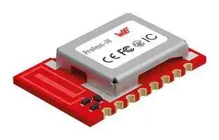
Even with it’s small dimensions of 8 x 12 mm the Proteus-III-SPI provides a strongly miniaturized integrated PCB antenna. Beside it is possible to connect an external antenna if high radio ranges are of interest.
The main functionality is accessible through pads with edge castellation. This offers easy prototype building as it is suitable for hand soldering. More optional GPIOs without enlarging the size are accessible through land grid pads that can only be connected through reflow process.
Figure 1: Proteus-III-SPI
Order code 2611011024010 Version 1.4, June 2023
13 _www.we-online.com/wcs_
**WIRELESS CONNECTIVITY & SENSORS** ~~OO~~ **User manual Proteus-III-SPI**
## **1.1.1. Key features**
The Proteus-III-SPI offers the following key features that are described in the manual in more detail:
- **SPP-like connection-based secured data transmission:** The Proteus-III-SPI firmware implements an SPP-like Bluetooth[®] LE profile that allows the bidirectional data transmission between several Proteus-III-SPI and/or to other Bluetooth[®] LE devices implementing the WE SPP-like profile. Any module in the network can initiate a connection setup. Secured connections allow the transmission of encrypted data.
- **Remote GPIOs:** The Proteus-III-SPI firmware allows to switch free module GPIOs via remote control. More information can be found in chapter 10 .
- **Advanced customization capabilities:** The configurable Device Information Service (DIS), the UUID and the appearance of the Bluetooth[®] LE profile, enable to personalize the Proteus-III-SPI to fuse with the user’s end product.
- **Low power position sensing solutions:** The current TX power of any Proteus-III-SPI is always transmitted with each advertising packet when the module is in command mode. With this, distance estimation and position sensing solutions can be realized conveniently by performing a passive scan.
- **Fast serial interface:** The Proteus-III-SPI offers a SPI-interface and the slave role to communicate with a host (SPI master) using a simple command interface.
- **Latest microprocessor generation provided by Nordic Semiconductor nRF52 series:** The heart of the Proteus-III-SPI is a Bluetooth[®] LE chip of the nRF52 series offering high performance values combined with low power consumption. It is a 32 Bit ARM Cortex-M4F CPU with 1024 kB flash + 256 kB RAM and up to 8 dBm output power.
- **Bluetooth[®] 5 stack:** The Bluetooth[®] 5 stack enables fast and energy efficient data transmission using state-of-the-art technology of Nordic Semiconductors.
- **High throughput mode:** The Proteus-III-SPI contains the so called "High throughput mode" that allows to send up to 4 data packets per connection interval. This increases significantly the throughput. This mode and its usage is described in application note ANR006 [4].
- **All Bluetooth[®] LE roles supported:** The integrated Bluetooth[®] LE stack supports all Bluetooth[®] LE roles. Depending on the current state of operation the Proteus-III-SPI firmware automatically switches its role to execute the user’s instructions.
- **Flexible wired interfacing:** The Proteus-III-SPI is equipped with extra pins suited for custom device/sensor connection. With help of these, a tailored firmware can be developed which is optimized to the customer’s needs. The pins can be configured to various functions such as UART, SPI, I2C, ADC, PWM, NFC and GPIO.
- **OTA firmware update:** The Proteus-III-SPI firmware provides over the air firmware update capabilities. Firmware updates can be applied using the Nordic Apps for cell phones.
- **Additional Bluetooth[®] 5 radio modes:** The Proteus-III-SPI provides the advanced radio modes 2 MBit mode for faster data transmission and the LE coded mode, that allows long range data transmissions. For more information, see chapter 5.11 .
Order code 2611011024010 Version 1.4, June 2023
14 _www.we-online.com/wcs_
**WIRELESS CONNECTIVITY & SENSORS** ~~OO~~ **User manual Proteus-III-SPI**
- **Long range connect:** For backward compatibility reasons, a Bluetooth[®] LE connection is setup using the legacy 1 MBit radio mode and can then be updated to long range mode. The Proteus-III-SPI allows in addition to setup the connection immediately using the long range mode, such that even connections can be initiated on high distances. More information can be found in chapter 5.12 .
- **Fast sensor data transmission via Beacons:** The Proteus-III-SPI supports the transmission and reception of Beacons. Beacons are fast broadcast messages that allow the energyefficient unidirectional transmission of data. Especially in sensor networks, this feature is suitable for the frequent transmission of measurement data as it avoids the need for a connection-based communication and therefore is more energy efficient.
## **1.1.2. Connectivity**
The Bluetooth[®] LE standard allows to setup a network with various Bluetooth[®] LE devices from different manufacturers. To be able to communicate with Proteus-III-SPI devices, the WE SPPlike profile must be known and implemented by all network participants.
The advanced developer guide of Proteus-III-SPI (application note ANR009 [5]) contains the design data of the WE SPP-like profile, to implement it for example in smart phone apps.
Order code 2611011024010 Version 1.4, June 2023
15 _www.we-online.com/wcs_
**WIRELESS CONNECTIVITY & SENSORS User manual Proteus-III-SPI**
## **1.2. Block diagram**
**==> picture [461 x 434] intentionally omitted <==**
**----- Start of picture text -----**<br>
Proteus-III-SPI<br>Shielding<br>Wireless MCU<br>SPI, INT,<br>Reset, GPIO, ARM Cortex M4,<br>SWD Flash, RAM<br>Power DCDC voltage<br>supply regulator<br>Radio core,<br>High accuracy<br>2.4GHz<br>crystal<br>Bluetooth 5.1<br>external wiring<br>RF Filter & 50Ω<br>according to trace<br>matching<br>design<br>50Ω port to λ/4<br>antenna<br>Antenna<br>i |.<br>©)<br>Figure 2: Block diagram of the module<br>1.3. Ordering information<br>**----- End of picture text -----**<br>
|WE order code|Description|
|---|---|
|2611011024010|Proteus-III-SPI Bluetooth® LE Module, Tape & Reel<br>(4-wire SPI + interrupt pin)|
|2611011024000|Proteus-III Bluetooth® LE Module, Tape & Reel<br>(UART)|
|2611119024011|Proteus-III-SPI mini EV board|
|2611036024001|USB Dongle Proteus-III USB radio stick, integrated<br>antenna|
Table 1: Ordering information
Order code 2611011024010 Version 1.4, June 2023
16
_www.we-online.com/wcs_
**WIRELESS CONNECTIVITY & SENSORS** ~~OO~~ **User manual Proteus-III-SPI**
## **2. Electrical specifications**
As not otherwise stated measured on the evaluation board Proteus-III-SPI-EV with T = 25 °C, VDDS =3 V, f = 2.44GHz, internal DC-DC converter in use.
## **2.1. Recommended operating conditions**
|Description|Min.|Typ.|Max.|Unit|
|---|---|---|---|---|
|Ambient temperature|-40|25|85|°C|
|Supply voltage (VDDS)|1.81|3|3.6|V|
|Supply rise time (0V to_≥_1.7V)|||60|ms|
Table 2: Recommended operating conditions
The on-chip power-on reset circuitry may not function properly for rise times longer than the specified maximum.
An instable supply voltage may significantly decrease the radio performance and stability.
## **2.2. Absolute maximum ratings**
|Description|Min.|Typ.|Max.|Unit|
|---|---|---|---|---|
|Supply voltage (VDD)|-0.3||+3.9|V|
|Voltage on any digital pin, VDD_<_3.6 V|-0.3||VDD+0.3|V|
|Voltage on any digital pin, VDD_≥_3.6 V|-0.3||3.9|V|
|Input RF level|||10|dBm|
|Flash endurance|10 000|||Write/erase cycles|
Table 3: Absolute maximum ratings
> 1Power fail comparator is set to 1.8 V to avoid flash fail due to voltage drop.
Order code 2611011024010 Version 1.4, June 2023
17 _www.we-online.com/wcs_
**WIRELESS CONNECTIVITY & SENSORS** ~~OO~~ **User manual Proteus-III-SPI**
## **2.3. Power consumption**
## **2.3.1. Static**
|Continuous test mode|Min.|Typ.|Max.|Unit|
|---|---|---|---|---|
|TX current consumption atRF_TXPower= 8||16.41||mA|
|TX current consumption atRF_TXPower= 0||6.41||mA|
|RX current consumption||6.251||mA|
|TX current consumption atRF_TXPower= 8||18.92||mA|
|TX current consumption atRF_TXPower= 0||82||mA|
|RX current consumption||7.72||mA|
|Sleep (system off mode)||0.4||µA|
Table 4: Power consumption for 100% transmission/reception
Due to the Bluetooth[®] LE time slot operation, the real operating currents are reduced significantly and depend on the user selectable advertising and connection interval settings.
> 1Transmitter only with DC/DC converter from nRF52 data sheet, CPU current not included.
> 2Full module power consumption.
Order code 2611011024010 Version 1.4, June 2023
18
_www.we-online.com/wcs_
> **WIRELESS CONNECTIVITY & SENSORS** ~~see~~ **User manual Proteus-III-SPI**
Figure 3: Radio transmitting @ 8 dBm output power, 1 Mbps Bluetooth[®] LE mode, Clock = HFXO, Regulator = DC/DC (typical values)
## **2.3.2. Dynamic**
Besides the static TX, RX, idle and sleep current, the average current is of interest. Here an example for a typical behavior of a peripheral device in advertising mode (see Figure 4 ). Currents and state durations are dependent on the configuration of the module. In this state the module transmits the advertising packets on the three advertising channels.
Nordic Semiconductor provides an online tool calculating the average current of a Bluetooth[®] connection. It can be accessed at _https://devzone.nordicsemi.com/power/_ .
Order code 2611011024010 Version 1.4, June 2023
19 _www.we-online.com/wcs_
> **WIRELESS CONNECTIVITY & SENSORS** ~~eT~~ **User manual Proteus-III-SPI**
Figure 4: Current consumption calculation in advertising mode with 40ms advertising interval with 8 dBm output power, UART/SPI disabled
Order code 2611011024010 Version 1.4, June 2023
20 _www.we-online.com/wcs_
**WIRELESS CONNECTIVITY & SENSORS** ~~OO~~ **User manual Proteus-III-SPI**
## **2.4. Radio characteristics**
Specifications of timing and RSSI value
|Description|Min.|Typ.|Max.|Unit|
|---|---|---|---|---|
|RSSI accuracy valid range (±2dB)|-90||-20|dBm|
|Enable TX or RX delay||140||µs|
|Enable TX or RX delay (fast mode)||40||µs|
|Disable TX delay||6||µs|
|Disable RX delay||0||µs|
Table 5: Timing and RSSI
|Description|Typ.|Unit|
|---|---|---|
|Output power (RF_TXPower= 8, conducted)|+6|dBm|
|Output power integrated antenna (RF_TXPower= 8, e.r.p.)|+4|dBm|
|Input sensitivity conducted (BER=1E-3, 1Mbps)|-92|dBm|
|Input sensitivity integrated antenna (BER=1E-3, 1Mbps)|-90|dBm|
Table 6: Transmit and receive power
All transmit and receive power levels are measured on the evaluation board. The values already include losses of transitions from module to motherboard to SMA or modules PCB antenna. They are realistic values for the end application. Sensitivity in the table above is stated for the common used bit error rate of 0.1%. In the table below the sensitivity is stated for a packet error rate of 1% with a payload length of 38 byte at different data rates. The PER 1% is a harder criteria resulting in 2 dBm less sensitivity.
|Description|Typ.|Unit|
|---|---|---|
|1 Mbit Phy ( PER 1% )|-90|dBm|
|2 Mbit Phy ( PER 1% )|-87|dBm|
|LE coded S=2 ( PER 1% )|-94|dBm|
|LE coded S=8 ( PER 1% )|-97|dBm|
Table 7: Sensitivity at different data rates
Order code 2611011024010 Version 1.4, June 2023
21 _www.we-online.com/wcs_
**WIRELESS CONNECTIVITY & SENSORS** ~~OO~~ **User manual Proteus-III-SPI**
## **2.5. Pin characteristics**
Specifications from nRF52 data sheet
|Description|Min.|Typ.|Max.|Unit|
|---|---|---|---|---|
|Input high voltage|0.7 ×VCC||VCC|V|
|Input low voltage|VSS||0.3 ×VCC|V|
|Current at VSS+0.4 V, output set low, standard<br>drive, VDD_≥_1.7V|1|2|4|mA|
|Current at VSS+0.4 V, output set low, high drive,<br>VDD_≥_2.7 V|6|10|15|mA|
|Current at VSS+0.4 V, output set low, high drive,<br>VDD_≥_1.7 V|3|||mA|
|Current at VDD-0.4 V, output set high, standard<br>drive, VCC_≥_1.7V|1|2|4|mA|
|Current at VDD-0.4 V, output set high, high<br>drive, VDD_≥_2.7 V|6|9|14|mA|
|Current at VDD-0.4 V, output set high, high<br>drive, VDD_≥_1.7 V|3|||mA|
|Internal pull-up resistance|11|13|16|kΩ|
|Internal pull-down resistance|11|13|16|kΩ|
Table 8: Pin characteristics
Order code 2611011024010 Version 1.4, June 2023
22 _www.we-online.com/wcs_
**WIRELESS CONNECTIVITY & SENSORS User manual Proteus-III-SPI**
## **3. Pinout**
**==> picture [449 x 378] intentionally omitted <==**
**----- Start of picture text -----**<br>
ANT<br>RF<br>S|<br>GND GND<br>RS L _ _By<br>SWDCLK WAKE_UP/SPI_INT<br>SS NN<br>SWDIO<br>SPI_CLK<br>SS SS<br>/RESET SPI_CS<br>SS N SS<br>BOOT SPI_MOSI<br>VDD NNNN SPI_MISO<br>B- NNNFoe &=<br>1<br>1<br>8<br>B<br>1<br>B6<br>B 1<br>8 3<br>3<br>9 12<br>MODE_1 BUSY LED_1 LED_2<br>**----- End of picture text -----**<br>
Figure 5: Pinout (top view)
The main functionality is accessible through pad 1 - 18 with edge castellation. This offers easy prototype building as it is suitable for hand soldering. More optional GPIOs without enlarging the size are accessible through the land grid pads B1 - B6 that can only be connected through re-flow process.
Order code 2611011024010 Version 1.4, June 2023
23
_www.we-online.com/wcs_
**WIRELESS CONNECTIVITY & SENSORS** ~~OO~~ **User manual Proteus-III-SPI**
|No|µC Pin|Designation|I/O|Description|
|---|---|---|---|---|
|1||_ANT_|I/O|RF connection to PCB antenna.<br>(see sec-<br>tion4.2)|
|2||_RF_|I/O|50 ΩRF connection through radio front end to<br>transceiver part of chipset. (see section4.2)|
|3||_GND_|Supply|Ground|
|4||_SWDCLK_|Input|Serial wire clock (SWD Interface). Uses inter-<br>nal pull down resistor.<br>Do not connect if not<br>needed.|
|5||_SWDIO_|Input|Serial wire input/output (SWD Interface). Uses<br>internal pull up resistor. Do not connect if not<br>needed.|
|6|P0.18|_/RESET_|Input|Reset pin. A low signal resets the module. Uses<br>internal pull up resistor.|
|7|P0.02|_BOOT_|Input|Boot pin. A low signal during and short after re-<br>set starts the module in OTA bootloader mode.<br>Uses internal pull up resistor1. Do not connect<br>if not needed.|
|8||_VDD_|Supply|Supply voltage|
|9|P0.19|_MODE_1_|Input|Operation mode pin with internal pull down re-<br>sistor1 during start-up. Do not connect.|
|10|P0.22|_BUSY_|Output|Do not connect.|
|11|P0.00/XL12|_LED_1_|Output|Indicates the module state (active high). Do not<br>connect if not needed.|
|12|P0.01/XL22|_LED_2_|Output|Indicates the module state (active high). Do not<br>connect if not needed.|
|13|P1.08|_SPI_MISO_|Output|SPI Master in, slave out signal. In sleep mode,<br>this pin is high.|
|14|P1.09|_SPI_MOSI_|Input|SPI Master out, slave in signal.|
|15|P0.11|_SPI_CS_|Input|SPI chip select signal.|
Table 9: Pinout, first part
> 1Internal pull ups or pull downs are configured at startup by the firmware installed in the SoC. The pull up on the _/RESET_ pin cannot be disabled by firmware.
> 2Pins available to connect an external crystal in custom firmware. The standard firmware of Proteus-III-SPI does not implement this function.
> 3NFC pins available for NFC function in custom firmware. The standard firmware of Proteus-III-SPI does not implement this function.
Order code 2611011024010 Version 1.4, June 2023
24 _www.we-online.com/wcs_
**WIRELESS CONNECTIVITY & SENSORS** ~~OO~~ **User manual Proteus-III-SPI**
|No|µC Pin|Designation|I/O|Description|
|---|---|---|---|---|
|16|P0.12|_SPI_CLK_|Input|SPI clock signal.|
|17|P0.03|_WAKE_UP_/_SPI_INT_|Input /<br>Output|Shared pin for wake-up from sleep<br>mode, and SPI data indication.<br>See<br>chapters5.4and6.1.2for more details.|
|18||_GND_|Supply|Ground|
|B1|P0.09/NFC13|_B1_|GPIO|Pin for remote GPIO access.<br>Do not<br>connect, if not needed.|
|B2|P0.10/NFC23|_B2_|GPIO|Pin for remote GPIO access.<br>Do not<br>connect, if not needed.|
|B3|P0.23|_B3_|GPIO|Pin for remote GPIO access.<br>Do not<br>connect, if not needed.|
|B4|P1.00|_B4_|GPIO|Pin for remote GPIO access.<br>Do not<br>connect, if not needed.|
|B5|P0.21|_B5_|GPIO|Pin for remote GPIO access.<br>Do not<br>connect, if not needed.|
|B6|P0.07|_B6_|GPIO|Pin for remote GPIO access.<br>Do not<br>connect, if not needed.|
Table 10: Pinout, second part
Order code 2611011024010 Version 1.4, June 2023
25 _www.we-online.com/wcs_
**WIRELESS CONNECTIVITY & SENSORS** ~~OO~~ **User manual Proteus-III-SPI**
## **4. Quick start**
## **4.1. Minimal pin connections**
**==> picture [444 x 252] intentionally omitted <==**
**----- Start of picture text -----**<br>
5 /RESET<br>e@ ,<br>1<br>VDD VDD<br>3 SPI INT/WAKE-UP ‘WORTH ELUKTRONIK ANT<br>4<br>2 SPI: CS,CLK,MISO,MOSI RF<br>Host '=- Proteus –III-SPI<br>Controller (SPI Slave)<br>(SPI Master) @ 6 BOOT/MODE_1 ,<br>7 LED_1/LED_2<br>8<br>GND<br>1<br>SWDIO/SWDCLK<br>**----- End of picture text -----**<br>
Figure 6: Minimal pin connections
The above image shows the steps to be performed to integrate the Proteus-III-SPI into a custom end device.
1. Supply voltage and ground Connect the _VDD_ and _GND_ pins to supply the radio module with power.
2. SPI interface to the host
- Connect the SPI pins _SPI_CS_ , _SPI_CLK_ , _SPI_MOSI_ and _SPI_MISO_ to the host to control the module via host.
3. SPI interrupt and wake-up from sleep Connect the shared pin _SPI_INT_ / _WAKE_UP_ to the host.
4. Antenna connection
- The antenna configuration must be done. See chapter 4.2 for details.
5. Reset
- Connect the _/RESET_ pin to the host to allow a hard reset of the module.
6. (Optional) FOTA and mode selection
Order code 2611011024010 Version 1.4, June 2023
26 _www.we-online.com/wcs_
**WIRELESS CONNECTIVITY & SENSORS** ~~OO~~ **User manual Proteus-III-SPI**
- Connect the _BOOT_ pin to the host controller to set the module into boot mode to enable firmware updates via radio.
7. (Optional) Status indication
- Connect the _LED_1_ and _LED_2_ pins to the host controller to allow easy indication of the status.
8. (Optional) Flash and debug interface
- In case of custom firmware development, it is recommended to additionally have the pins _SWDIO_ and _SWDCLK_ accessible in order to support a fail-safe update of firmware. A standard socket on the customer’s PCB for connecting a flash adapter can be useful for debugging purposes (e.g. a JTAG 2*10 pin header with 2.54 mm pin-to-pin distance).
The logic level of the module is based on 3 V. A 5 V logic level must not be connected directly to the module.
Order code 2611011024010 Version 1.4, June 2023
27 _www.we-online.com/wcs_
**WIRELESS CONNECTIVITY & SENSORS** ~~OO~~ **User manual Proteus-III-SPI**
## **4.2. Antenna connection**
Proteus-III-SPI’s smart antenna configuration enables the user to choose between two antenna options:
## **4.2.1. On-board PCB antenna**
The Proteus-III-SPI has an on-board PCB antenna optimized for strong miniaturization operating in the 2.4 GHz frequency band. A simple short between the pins _RF_ and _ANT_ feeds the RF output of the module to the on-board antenna of the Proteus-III-SPI. In this configuration, the module does not require any additional RF circuitry. For US and Canada, please refer to the trace design in chapter 16.3 .
## **4.2.2. External antenna**
For applications that use an external antenna, the Proteus-III-SPI provides a 50 Ω RF signal on pin _RF_ of the module. In this configuration, pin _ANT_ of the module has to be connected to ground and pin _RF_ to the external antenna via 50 Ω feed line. Refer to chapter 16 for further information.
The use cases for the integrated antenna are miniaturization and re-use of module certifications for the end-application. The use cases for the external antenna are optimization of radio range spending more space for the antenna and differentiated antenna for example when metal housings are used.
Order code 2611011024010 Version 1.4, June 2023
28 _www.we-online.com/wcs_
**WIRELESS CONNECTIVITY & SENSORS** ~~OO~~ **User manual Proteus-III-SPI**
## **4.3. Power up**
After powering the module the _/RESET_ pin shall be hold for another ∆t of 1ms after the _VDD_ is stable to ensure a safe start-up. The module will send a CMD_GETSTATE_CNF (0x02 41 02 00 01 01 41) to indicate "ready for operation" after the _/RESET_ pin was released.
Applying a reset (e.g. a host temporarily pulling the _/RESET_ pin down for at least 1ms and releasing it again) after the VCC is stable will also be sufficient.
## **4.4. Test the SPI interface**
To test the SPI transaction in command mode, perform a pin reset by pulling the _/RESET_ pin down for at least 1 ms and release it again. To do so, the reset button can be simply pressed, in case a Proteus-III-SPI mini evaluation board is used. After this reset, the Proteus-III-SPI restarts and wants to transmit a CMD_GETSTATE_CNF (0x02 41 02 00 01 01 41) message to the connected host. Thus, the Proteus-III-SPI sets the interrupt pin _SPI_INT_ to its "active level" to signalize that the module has data available to be fetched by the host.
The default "active level" of the _SPI_INT_ is HIGH. It can be configured using the user setting SPI_ConfigIndex .
Next, the host controller must read the first 4 bytes via SPI from the radio module, interpret the length field of the command frame and read the remaining bytes (payload and check sum). For a detailed description, please see figure 10 in the chapter Host connection .
If the transfer of SPI data from radio module to the host was been run successfully, the direction host to radio module can be tested. Thus, sent for example a CMD_GETSTATE_REQ (0x02 01 00 00 03) command to the module, and check if it responds with a CMD_GETSTATE_CNF (0x02 41 02 00 01 01 41) message. To do so, sent the whole frame 0x02 01 00 00 03 in one SPI transaction to the radio module, as shown in figure 9 in the chapter Host connection . If this has been successful, the radio module responds again with a CMD_GETSTATE_CNF message, as described previously (by pulling the _SPI_INT_ to its active state, reading 4 bytes, interpreting the length field, reading the remaining bytes).
Order code 2611011024010 Version 1.4, June 2023
29 _www.we-online.com/wcs_
**WIRELESS CONNECTIVITY & SENSORS** ~~OO~~ **User manual Proteus-III-SPI**
## **4.5. Quickstart example**
This section describes how to quick start the data transmission between two Proteus-III-SPI modules. The goal is to setup a Bluetooth[®] LE connection between module A and module B, transmit some data and close the connection again.
The below commands are in hexadecimal notation. The arrow in the left column describes, whether it’s a message from host to radio module, or vice versa. A request command is always sent from host to module ( _⇒_ ). An indication, confirmation or response message is always sent from module to host ( _⇐_ ).
Connect the two modules to a microcontroller with SPI interface (see chapter 6 ).
To reproduce the following sequence, note that the MAC address FS_BTMAC of every module is different. Thus it has to be replaced in the example commands below. In addition, the checksum has to be adjusted, when adapting any command. The command structure and checksum calculation is described in chapter 7 .
Order code 2611011024010 Version 1.4, June 2023
30 _www.we-online.com/wcs_
**WIRELESS CONNECTIVITY & SENSORS** ~~OO~~ **User manual Proteus-III-SPI**
## **Connection setup and first data transmission**
1. Power-up the modules and make their SPIs accessible by the host(s). After the power-up or after reset the following sequence is available in the radio module to be fetched by the host.
|Info|Module A|Module B|
|---|---|---|
|_⇐_ResponseCMD_GETSTATE_CNF: Module A<br>started inACTION_IDLEmode.|02 41 02 00 01 01 41||
|_⇐_ResponseCMD_GETSTATE_CNF: Module B<br>started inACTION_IDLEmode.||02 41 02 00 01 01 41|
## 2. Request the FS_BTMAC of both modules.
|Info|Module A|Module B|
|---|---|---|
|_⇒_RequestCMD_GET_REQwith settings index 4|02 10 01 00 04 17||
|_⇐_ResponseCMD_GET_CNF: FS_BTMACof<br>module A is0x55 0x00 0x00 0xDA 0x18 0x00|02 50 07 00 0055 00<br>00 DA 18 00C2||
|_⇒_RequestCMD_GET_REQwith settings index 4||02 10 01 00 04 17|
|_⇐_ResponseCMD_GET_CNF: FS_BTMACof<br>module B is0x11 0x00 0x00 0xDA 0x18 0x00||02 50 07 00 0011 00<br>00 DA 18 0086|
## 3. Connect module A to module B via Bluetooth[®] .
|Info|Module A|Module B|
|---|---|---|
|_⇒_RequestCMD_CONNECT_REQwithFS_BTMACof<br>module B|02 06 06 0011 00 00<br>DA 18 00D1||
|_⇐_ResponseCMD_CONNECT_CNF: Request<br>understood, try to connect now|02 46 01 00 00 45||
|_⇐_IndicationCMD_CONNECT_IND: Physical<br>connection established successfully to module<br>withFS_BTMAC0x11 0x00 0x00 0xDA 0x18 0x00|02 86 07 00 0011 00<br>00 DA 18 0050||
|_⇐_IndicationCMD_CONNECT_IND: Physical<br>connection established successfully to module<br>withFS_BTMAC0x55 0x00 0x00 0xDA 0x18 0x00||02 86 07 00 0055 00<br>00 DA 18 0014|
|_⇐_IndicationCMD_CHANNELOPEN_RSP: Channel<br>opened successfully to module withFS_BTMAC<br>0x11 0x00 0x00 0xDA 0x18 0x00and maximum<br>payload size of0xF3(243 Bytes) per packet|02 C6 08 00 0011 00<br>00 DA 18 00F3E3||
|_⇐_IndicationCMD_CHANNELOPEN_RSP: Channel<br>opened successfully to module withFS_BTMAC<br>0x55 0x00 0x00 0xDA 0x18 0x00and maximum<br>payload size of0xF3(243 Bytes) per packet||02 C6 08 00 0055 00<br>00 DA 18 00F3A7|
Order code 2611011024010 Version 1.4, June 2023
31
_www.we-online.com/wcs_
**WIRELESS CONNECTIVITY & SENSORS** ~~OO~~ **User manual Proteus-III-SPI**
4. Once the connection is active, data can be sent in each direction. Let us send a string "ABCD" from module B to module A.
The RSSI values will be different in your tests.
|Info|Module A|Module B|
|---|---|---|
|_⇒_RequestCMD_DATA_REQ: Send "ABCD" to<br>module A||02 04 04 0041 42 43<br>4406|
|_⇐_ResponseCMD_DATA_CNF: Request received,<br>send data now||02 44 01 00 00 47|
|_⇐_IndicationCMD_DATA_IND: Received string<br>"ABCD" fromFS_BTMAC0x11 0x00 0x00 0xDA<br>0x18 0x00with RSSI of 0xCA (-54 dBm)|02 84 0B 0011 00<br>00 DA 18 00CA41<br>42 43 4490||
|_⇐_ResponseCMD_TXCOMPLETE_RSP: Data<br>transmitted successfully||02 C4 01 00 00 C7|
## 5. Reply with "EFGH" to module B.
|Info|Module A|Module B|
|---|---|---|
|_⇒_RequestCMD_DATA_REQ: Send "EFGH" to<br>module B|02 04 04 0045 46 47<br>480E||
|_⇐_ResponseCMD_DATA_CNF: Request received,<br>send data now|02 44 01 00 00 47||
|_⇐_IndicationCMD_DATA_IND: Received string<br>"EFGH" fromFS_BTMAC0x55 0x00 0x00 0xDA<br>0x18 0x00with RSSI of 0xC1 (-63dBm)||02 84 0B 0055 00<br>00 DA 18 00C145<br>46 47 48D7|
|_⇐_ResponseCMD_TXCOMPLETE_RSP: Data<br>transmitted successfully|02 C4 01 00 00 C7||
6. Now module A closes the Bluetooth[®] LE connection, so both modules will get a disconnect indication message.
|Info|Module A|Module B|
|---|---|---|
|_⇒_RequestCMD_DISCONNECT_REQ: Disconnect|02 07 00 00 05||
|_⇐_ResponseCMD_DISCONNECT_CNF: Request<br>received, disconnect now|02 47 01 00 00 44||
|_⇐_IndicationCMD_DISCONNECT_IND: Connection<br>closed|02 87 01 00 16 92||
|_⇐_IndicationCMD_DISCONNECT_IND: Connection<br>closed||02 87 01 00 13 97|
Order code 2611011024010 Version 1.4, June 2023
32 _www.we-online.com/wcs_
**WIRELESS CONNECTIVITY & SENSORS** ~~OO~~ **User manual Proteus-III-SPI**
## **5. Functional description**
## **5.1. Operation modes**
The Proteus-III-SPI module acts as a slave and can be fully controlled by an external host. The Proteus-III-SPI supports the following operating modes:
- The **command mode** , where the Proteus-III-SPI can be controlled by the host controller via commands. The command mode allows to use all central and peripheral function of the radio module. The functions of the radio module, like data transmission or configuration tasks, can be triggered by predefined commands (see chapter 7 ) that are sent as telegrams over the SPI interface.
## **5.2. Radio module states**
The Proteus-III-SPI can operate in different states. Depending on the active state several commands of the command interface (see chapter 7 ) are permitted to modify the state, configure the module or transmit data over the radio interface. An overview of the different states and the corresponding allowed commands can be found in Figure 7 .
When the Proteus-III-SPI is powered up, it starts in ACTION_IDLE state. In this state the module advertises (Bluetooth[®] LE role "peripheral"), such that other devices in range can detect it and connect to it.
The ACTION_IDLE state also allows to switch to ACTION_SCANNING state, where the module stops advertising and scans for other advertising Bluetooth[®] LE devices in range.
When leaving the ACTION_SCANNING state with the corresponding command, the module is in ACTION_IDLE state and starts advertising again.
The ACTION_CONNECTED state can be entered, either by getting a connection request from another Bluetooth[®] LE device, or by setting up a connection itself. In this case, it stops advertising and data can be transmitted and received to/from the connected Bluetooth[®] LE device. This state remains active as long as the module does not disconnect itself, and no disconnection request from the connected remote device is received.
When disconnecting, the module goes to ACTION_IDLE state and starts advertising again, to be ready for the next connection setup.
Order code 2611011024010 Version 1.4, June 2023
33 _www.we-online.com/wcs_
**WIRELESS CONNECTIVITY & SENSORS** ~~oo~~ **User manual Proteus-III-SPI**
**==> picture [427 x 672] intentionally omitted <==**
**----- Start of picture text -----**<br>
ACTION_DTM<br>ACTION_SCANNING<br>The module is in direct<br>The module scans for other advertising Proteus test mode.<br>modules in range.<br>Permitted commands: Permitted commands:<br>CMD_RESET_REQ, CMD_GETSTATE_REQ, CMD_DTM_REQ,<br>CMD_SCANSTOP_REQ, CMD_GET_REQ CMD_RESET_REQ,<br>a CMD_GETSTATE_REQ<br>a KB!Y —<br>i? o KR=<br>% £ Q!<br>4 = Ss<br>o4 of o<br>% &<br>ACTION_IDLE ACTION_SLEEP<br>The module advertises and waits for incoming connection The module is in sleep mode<br>indications. If no connection will be established, it goes to sleep. The and waits for a wakeup-<br>module can establish a connection to another module in range by event.<br>itself.<br>Permitted commands:<br>Permitted commands: None<br>CMD_RESET_REQ, CMD_FACTORYRESET_REQ,CMD_GETSTATE_REQ, CMD_CONNECT_REQ, CMD_SLEEP_REQ, CMD_SETBEACON_REQ, ih eo?ves~~so 7;<br>CMD_SCANSTART_REQ, CMD_GET_REQ, 7S<br>Wake-up<br>CMD_GETDEVICES_REQ, CMD_SET_REQ,<br>CMD_BOOTLOADER_REQ, event<br>CMD_DTMSTART_REQ, CMD_PASSKEY_REQ,<br>CMD_GETBONDS_REQ, CMD_DELETEBONDS_REQ,<br>CMD_NUMERIC_COMP, CMD_GPIO_LOCAL_CONFIG_REQ,<br>q Start<br>CMD_GPIO_REMOTE_WRITE_REQ, CMD_GPIO_REMOTE_READ_REQ,<br>CMD_GPIO_LOCAL_WRITE_REQ, CMD_GPIO_LOCAL_READ_REQ,<br>CMD_ALLOWUNBONDEDCONNECTIONS_REQ<br>fo) 3°<br>%%\a\ 2 no Reset<br>BZ<br>Zz 4 re)<br>a5 33<br>‘%,\ 2Ke) \g'oiS)<br>aS<br>Ok? 33&&<br>a0<br>\_'p )<br>Ra S mp %%<br>2%,<br>ACTION_CONNECTED \ %%,<br>O's<br>~. &<br>The module is connected. %%% Cl<br>Now data can be transmitted. ee<br>S.<br>Permitted commands: BOOTLOADER<br>CMD_RESET_REQ, CMD_GETSTATE_REQ,<br>CMD_DATA_REQ, CMD_DISCONNECT_REQ, The module can be updated<br>CMD_GETDEVICES_REQ, CMD_GET_REQ, over the air.<br>CMD_PHYUPDATE_REQ,<br>CMD_GPIO_REMOTE_WRITE_REQ, Permitted commands:<br>CMD_GPIO_REMOTE_READ_REQ, None<br>CMD_GPIO_LOCAL_WRITE_REQ, | a<br>CMD_GPIO_LOCAL_READ_REQ<br>**----- End of picture text -----**<br>
~~Figure 7: State overview~~
Order code 2611011024010 Version 1.4, June 2023
34
_www.we-online.com/wcs_
**WIRELESS CONNECTIVITY & SENSORS** ~~OO~~ **User manual Proteus-III-SPI**
## **5.3. State indication using the LED pins**
The pins _LED_1_ and _LED_2_ of the Proteus-III-SPI can be used to determine the module state. The states described in Figure 7 result in the following pin behavior. The pins on the ProteusIII-SPI are active high.
|State|_LED_1_|_LED_2_|
|---|---|---|
|ACTION_IDLE|Blinking (On for 200 ms, Off for<br>2800 ms)|Off|
|ACTION_SCANNING|Blinking (On for 1000 ms, Off for<br>1000 ms)|Off|
|ACTION_CONNECTED|On|Off, On (as soon as the channel<br>was opened successfully, see<br>CMD_CHANNELOPEN_RSP)|
|ACTION_SLEEP|Off|Off|
|ACTION_DTM|Off|Off|
|BOOTLOADERwaiting for<br>connection|On|Off|
|BOOTLOADERconnected,<br>firmware update running|Off|On|
Table 17: LED behavior of the Proteus-III-SPI
## **5.4. Sleep mode**
Especially for battery-powered devices the ACTION_SLEEP mode (system-off mode) supports very low power consumption. It can be entered by sending the command CMD_SLEEP_REQ to the module. As response, the module will send a CMD_SLEEP_CNF and then enter the ACTION_SLEEP mode.
In ACTION_SLEEP mode, the GPIO pins _B1_ - _B6_ are set to input during the sleep period. Furthermore the SPI is disabled. Thus the module will not receive or transmit any data. To prevent leakage current, the host shall pull the SPI pins to their default voltage levels and the shared _WAKE_UP_ / _SPI_INT_ pin to its "inactive level".
As the _WAKE_UP_ pin and _SPI_INT_ pin are shared, the radio module sets this pin to input function when it goes to sleep mode to detect a wake-up trigger from the host. As soon as this happened, the radio module can be woken up by setting the voltage level of the _WAKE_UP_ pin to its "active level" for at least 5 ms before setting it back to its "inactive level". The "active level" is defined by means of the user setting SPI_ConfigIndex (the default value is "active high").
The module then restarts completely, so that all volatile settings are set to default. In this case the _WAKE_UP_ / _SPI_INT_ pin of the radio module is set to output function to signalize to the host if there is data on the radio module that is supposed to be sent via SPI to the host controller. A CMD_GETSTATE_CNF will be sent when the module is ready for operation again.
Order code 2611011024010 Version 1.4, June 2023
35 _www.we-online.com/wcs_
**WIRELESS CONNECTIVITY & SENSORS** ~~OO~~ **User manual Proteus-III-SPI**
## **5.5.**
The Proteus-III-SPI can be identified on the radio interface by its FS_BTMAC . This FS_BTMAC is a Bluetooth[®] -conform MAC address, which is part of the data package sent during advertising in ACTION_IDLE mode. A FS_BTMAC has the size of 6 Bytes.
In ACTION_SCANNING state a module listens to the data packets of all advertising devices in range and stores their FS_BTMAC to an internal data base. With help of this FS_BTMAC a connection to the corresponding device can then be established using the CMD_CONNECT_REQ command. To simplify the identification of Proteus-III-SPI devices on the RF-interface a short user-defined name (see RF_DeviceName ) can be given to the module, which is also part of the advertising packet.
The FS_BTMAC consists of the Würth Elektronik eiSos MAC ID 0x0018DA followed by the module’s serial number FS_SerialNumber .
## **5.6. Connection based data transmission, with or without security**
In the Bluetooth[®] LE standard the data transmission typically is connection based. A connection between two devices can be secured or unsecured (default configuration). In any case, each data packet transmitted is acknowledged on the link layer, such that it is resent as long as it has not been received from the receiver. The following lines describe how to run the connection setup and data transmission using the Proteus-III-SPI.
If module A is supposed to setup a connection with module B, the host of module A must send the command CMD_CONNECT_REQ including the FS_BTMAC of module B to module A. If the FS_BTMAC of module B is unknown, a radio scan shall be run before by module A to discover all available Bluetooth[®] LE enabled devices in range.
After sending the command CMD_CONNECT_REQ , the module answers with a CMD_CONNECT_CNF to signal that the request has been understood and the module tries to establish the connection. If module B cannot be found on the air within a timeout, module A outputs a CMD_CONNECT_IND with "failed" as status. Otherwise, as soon as the physical connection has been set up successfully, module A and B output a CMD_CONNECT_IND message with the status of the successful connection and _LED_1_ turns on.
Next some security and authentication messages will follow, like CMD_SECURITY_IND , if security is enabled.
After the physical connection has been setup successfully the modules exchange their services (WE SPP-like). As soon as this has finished successfully, a CMD_CHANNELOPEN_RSP message is sent to the host indicating that the connection is ready for data transmission. In addition, _LED_2_ turns on.
Now, data can be transmitted in both directions using the command CMD_DATA_REQ . It is confirmed by the messages CMD_DATA_CNF (data will be processed) and CMD_TXCOMPLETE_RSP (data transmitted successfully).
Each time data has been received a CMD_DATA_IND message will be output containing the received data.
As soon as one module closes the connection using a CMD_DISCONNECT_REQ , both devices will
Order code 2611011024010 Version 1.4, June 2023
36 _www.we-online.com/wcs_
**WIRELESS CONNECTIVITY & SENSORS** ~~OO~~ **User manual Proteus-III-SPI**
inform their host by a CMD_DISCONNECT_IND message that the connection is no longer open. If a device is no longer within range, the CMD_DISCONNECT_IND message is triggered by a timeout.
An example of setting up an unsecured connection is shown in chapter 4.5 . How to setup a secured connection is shown in the preceding chapters. See also the application note "ANR009 advanced developer guide" to get detailed information about the connection setup with foreign devices.
## **5.6.1. Further information for a secure connection setup**
The RF_SecFlags parameter of the module determines the security mode. If a certain security mode of a Proteus-III-SPI peripheral device is set, its security level has to be met by the connecting central device to be able to exchange data. As long as the defined security level is not met by the central device, no access to the peripheral’s profiles will be granted.
When connecting from a Proteus-III-SPI to another Proteus radio module, you shall not use different security modes.
To get further information about the secured connection setup, when using a foreign device (i.e. mobile phone with a custom APP), please refer to the Proteus-III-SPI application note "ANR009 advanced developer guide".
## **5.6.1.1. Just works mode**
In case of the "Just works" mode, each time a connection is established, a new random key is exchanged in advance to be used for data encryption. Since no authentication will be performed, also devices without input and output capabilities (like keyboard or display) are able to connect to each other.
## **Example: Secured connection with LE Legacy security method "Just Works" without bonding**
1. Power-up the modules and make their SPIs accessible by the host(s). After the power-up or after reset the following sequence is available in the radio module to be fetched by the host.
|Info|Module A|Module B|
|---|---|---|
|_⇐_ResponseCMD_GETSTATE_CNF: Module A<br>started inACTION_IDLEmode.|02 41 02 00 01 01 41||
|_⇐_ResponseCMD_GETSTATE_CNF: Module B<br>started inACTION_IDLEmode.||02 41 02 00 01 01 41|
Order code 2611011024010 Version 1.4, June 2023
37 _www.we-online.com/wcs_
**WIRELESS CONNECTIVITY & SENSORS** ~~OO~~ **User manual Proteus-III-SPI**
2. Request the FS_BTMAC of both modules.
|Info|Module A|Module B|
|---|---|---|
|_⇒_RequestCMD_GET_REQwith settings index 4|02 10 01 00 04 17||
|_⇐_ResponseCMD_GET_CNF: FS_BTMACof<br>module A is0x55 0x00 0x00 0xDA 0x18 0x00|02 50 07 00 0055 00<br>00 DA 18 00C2||
|_⇒_RequestCMD_GET_REQwith settings index 4||02 10 01 00 04 17|
|_⇐_ResponseCMD_GET_CNF: FS_BTMACof<br>module B is0x11 0x00 0x00 0xDA 0x18 0x00||02 50 07 00 0011 00<br>00 DA 18 0086|
3. Configure the parameter RF_SecFlags to use "Just Works" pairing method for Bluetooth[®] security.
|Info|Module A|Module B|
|---|---|---|
|_⇒_PerformCMD_SET_REQwith settings index 12<br>and value 0x02 on module A|02 11 02 00 0C 02<br>1F||
|_⇐_ResponseCMD_SET_CNF(Module will restart<br>to adopt the new value)|02 51 01 00 00 52||
|_⇐_ResponseCMD_GETSTATE_CNF|02 41 02 00 01 01 41||
|_⇒_PerformCMD_SET_REQwith settings index 12<br>and value 0x02 on module B||02 11 02 00 0C 02<br>1F|
|_⇐_ResponseCMD_SET_CNF(Module will restart<br>to adopt the new value)||02 51 01 00 00 52|
|_⇐_ResponseCMD_GETSTATE_CNF||02 41 02 00 01 01 41|
## 4. Connect module A to module B via Bluetooth[®] .
|Info|Module A|Module B|
|---|---|---|
|_⇒_RequestCMD_CONNECT_REQwithFS_BTMACof<br>module B|02 06 06 0011 00 00<br>DA 18 00D1||
|_⇐_ResponseCMD_CONNECT_CNF: Request<br>understood, try to connect now|02 46 01 00 00 45||
|_⇐_IndicationCMD_CONNECT_IND: Physical<br>connection established successfully to module<br>withFS_BTMAC0x11 0x00 0x00 0xDA 0x18 0x00|02 86 07 00 0011 00<br>00 DA 18 0050||
|_⇐_IndicationCMD_CONNECT_IND: Physical<br>connection established successfully to module<br>withFS_BTMAC0x55 0x00 0x00 0xDA 0x18 0x00||02 86 07 00 0055 00<br>00 DA 18 0014|
|_⇐_IndicationCMD_SECURITY_IND, status0x02<br>(encrypted link, pairing, no bonding), with<br>FS_BTMAC0x11 0x00 0x00 0xDA 0x18 0x00|02 88 07 000211 00<br>00 DA 18 005C||
Order code 2611011024010 Version 1.4, June 2023
38
_www.we-online.com/wcs_
**WIRELESS CONNECTIVITY & SENSORS** ~~OO~~ **User manual Proteus-III-SPI**
|_⇐_IndicationCMD_SECURITY_IND, status0x02<br>(encrypted link, pairing, no bonding), with<br>FS_BTMAC0x55 0x00 0x00 0xDA 0x18 0x00||02 88 07 000255 00<br>00 DA 18 0018|
|---|---|---|
|Info|Module A|Module B|
|---|---|---|
|_⇐_IndicationCMD_CHANNELOPEN_RSP: Channel<br>opened successfully to module withFS_BTMAC<br>0x11 0x00 0x00 0xDA 0x18 0x00and maximum<br>payload size of0xF3(243 Bytes) per packet|02 C6 08 00 0011 00<br>00 DA 18 00F3EC||
|_⇐_IndicationCMD_CHANNELOPEN_RSP: Channel<br>opened successfully to module withFS_BTMAC<br>0x55 0x00 0x00 0xDA 0x18 0x00and maximum<br>payload size of0xF3(243 Bytes) per packet||02 C6 08 00 0055 00<br>00 DA 18 00F3A8|
5. Once the connection is active, data can be sent in each direction. Let us send a string "ABCD" from module B to module A.
The RSSI values will be different in your tests.
|Info|Module A|Module B|
|---|---|---|
|_⇒_RequestCMD_DATA_REQ: Send "ABCD" to<br>module A||02 04 04 0041 42 43<br>4406|
|_⇐_ResponseCMD_DATA_CNF: Request received,<br>send data now||02 44 01 00 00 47|
|_⇐_IndicationCMD_DATA_IND: Received string<br>"ABCD" fromFS_BTMAC0x11 0x00 0x00 0xDA<br>0x18 0x00with RSSI of 0xCA (-54 dBm)|02 84 0B 0011 00<br>00 DA 18 00CA41<br>42 43 4490||
|_⇐_ResponseCMD_TXCOMPLETE_RSP: Data<br>transmitted successfully||02 C4 01 00 00 C7|
## 6. Reply with "EFGH" to module B.
|Info|Module A|Module B|
|---|---|---|
|_⇒_RequestCMD_DATA_REQ: Send "EFGH" to<br>module B|02 04 04 0045 46 47<br>480E||
|_⇐_ResponseCMD_DATA_CNF: Request received,<br>send data now|02 44 01 00 00 47||
Order code 2611011024010 Version 1.4, June 2023
39 _www.we-online.com/wcs_
**WIRELESS CONNECTIVITY & SENSORS** ~~OO~~ **User manual Proteus-III-SPI**
|_⇐_IndicationCMD_DATA_IND: Received string<br>"EFGH" fromFS_BTMAC0x55 0x00 0x00 0xDA<br>0x18 0x00with RSSI of 0xC1 (-63dBm)||02 84 0B 0055 00<br>00 DA 18 00C145<br>46 47 48D7|
|---|---|---|
|_⇐_ResponseCMD_TXCOMPLETE_RSP: Data<br>transmitted successfully|02 C4 01 00 00 C7||
7. Now module A closes the connection, so both modules will get a disconnect indication.
|Info|Module A|Module B|
|---|---|---|
|_⇒_RequestCMD_DISCONNECT_REQ: Disconnect|02 07 00 00 05||
|_⇐_ResponseCMD_DISCONNECT_CNF: Request<br>received, disconnect now|02 47 01 00 00 44||
|_⇐_IndicationCMD_DISCONNECT_IND: Connection<br>closed|02 87 01 00 16 92||
|_⇐_IndicationCMD_DISCONNECT_IND: Connection<br>closed||02 87 01 00 13 97|
8. You may want to perform a CMD_FACTORYRESET_REQ to restore default settings.
## **5.6.1.2. StaticPasskey mode**
In case of the "StaticPasskey" mode, a pass key has to be entered at the central side that has to match the pass key of the peripheral. Here the Proteus-III-SPI uses a static pass key in the peripheral role that is stored in the parameter RF_StaticPasskey . When using this method, the central device requests its host to enter the correct pass key (see CMD_PASSKEY_IND ). In this case the pass key of the peripheral has to be entered on central side using the CMD_ PASSKEY_REQ command. If the entered pass key is correct, the channel will be opened for data transmission. Otherwise, the connection will be rejected.
## **Example: Secured connection with security method "StaticPasskey"**
1. Power-up the modules and make their SPIs accessible by the host(s). After the power-up or after reset the following sequence is available in the radio module to be fetched by the host.
|Info|Module A|Module B|
|---|---|---|
|_⇐_ResponseCMD_GETSTATE_CNF: Module A<br>started inACTION_IDLEmode.|02 41 02 00 01 01 41||
|_⇐_ResponseCMD_GETSTATE_CNF: Module B<br>started inACTION_IDLEmode.||02 41 02 00 01 01 41|
2. Request the FS_BTMAC of both modules.
Order code 2611011024010 Version 1.4, June 2023
40 _www.we-online.com/wcs_
**WIRELESS CONNECTIVITY & SENSORS** ~~OO~~ **User manual Proteus-III-SPI**
|Info|Module A|Module B|
|---|---|---|
|_⇒_RequestCMD_GET_REQwith settings index 4|02 10 01 00 04 17||
|_⇐_ResponseCMD_GET_CNF: FS_BTMACof<br>module A is0x55 0x00 0x00 0xDA 0x18 0x00|02 50 07 00 0055 00<br>00 DA 18 00C2||
|_⇒_RequestCMD_GET_REQwith settings index 4||02 10 01 00 04 17|
|_⇐_ResponseCMD_GET_CNF: FS_BTMACof<br>module B is0x11 0x00 0x00 0xDA 0x18 0x00||02 50 07 00 0011 00<br>00 DA 18 0086|
3. Configure the parameter RF_SecFlags to use "StaticPasskey" pairing method for Bluetooth[®] security.
|Info|Module A|Module B|
|---|---|---|
|_⇒_PerformCMD_SET_REQwith settings index 12<br>and value 0x03 on module A|02 11 02 00 0C 03<br>1E||
|_⇐_ResponseCMD_SET_CNF(Module will restart<br>to adopt the new value)|02 51 01 00 00 52||
|_⇐_ResponseCMD_GETSTATE_CNF|02 41 02 00 01 01 41||
|_⇒_PerformCMD_SET_REQwith settings index 12<br>and value 0x03 on module B||02 11 02 00 0C 03<br>1E|
|_⇐_ResponseCMD_SET_CNF(Module will restart<br>to adopt the new value)||02 51 01 00 00 52|
|_⇐_ResponseCMD_GETSTATE_CNF||02 41 02 00 01 01 41|
## 4. Connect module A to module B via Bluetooth[®] .
|Info|Module A|Module B|
|---|---|---|
|_⇒_RequestCMD_CONNECT_REQwithFS_BTMACof<br>module B|02 06 06 0011 00 00<br>DA 18 00D1||
|_⇐_ResponseCMD_CONNECT_CNF: Request<br>understood, try to connect now|02 46 01 00 00 45||
|_⇐_IndicationCMD_CONNECT_IND: Physical<br>connection established successfully to module<br>withFS_BTMAC0x11 0x00 0x00 0xDA 0x18 0x00|02 86 07 00 0011 00<br>00 DA 18 0050||
|_⇐_IndicationCMD_CONNECT_IND: Physical<br>connection established successfully to module<br>withFS_BTMAC0x55 0x00 0x00 0xDA 0x18 0x00||02 86 07 00 0055 00<br>00 DA 18 0014|
|_⇐_IndicationCMD_PASSKEY_INDto ask for the<br>pass key|02 8D 07 00 0011<br>00 00 DA 18 005B||
|_⇒_Answer with theCMD_PASSKEY_REQand the<br>pass key "123123"|02 0D 06 0031 32<br>33 31 32 3309||
|_⇐_ResponseCMD_PASSKEY_CNF: Pass key ok|02 4D 01 00 00 4E||
Order code 2611011024010 Version 1.4, June 2023
41 _www.we-online.com/wcs_
**WIRELESS CONNECTIVITY & SENSORS** ~~OO~~ **User manual Proteus-III-SPI**
|_⇐_IndicationCMD_SECURITY_IND, status0x02<br>(encrypted link, pairing, no bonding), with<br>FS_BTMAC0x11 0x00 0x00 0xDA 0x18 0x00|02 88 07 000211 00<br>00 DA 18 005C||
|---|---|---|
|_⇐_IndicationCMD_SECURITY_IND, status0x02<br>(encrypted link, pairing, no bonding), with<br>FS_BTMAC0x55 0x00 0x00 0xDA 0x18 0x00||02 88 07 000255 00<br>00 DA 18 0018|
|_⇐_IndicationCMD_CHANNELOPEN_RSP: Channel<br>opened successfully to module withFS_BTMAC<br>0x11 0x00 0x00 0xDA 0x18 0x00and maximum<br>payload size of0xF3(243 Bytes) per packet|02 C6 08 00 0011 00<br>00 DA 18 00F3EC||
|_⇐_IndicationCMD_CHANNELOPEN_RSP: Channel<br>opened successfully to module withFS_BTMAC<br>0x55 0x00 0x00 0xDA 0x18 0x00and maximum<br>payload size of0xF3(243 Bytes) per packet||02 C6 08 00 0055 00<br>00 DA 18 00F3A8|
5. Once the connection is active, data can be sent in each direction. Let us send a string "ABCD" from module B to module A.
The RSSI values will be different in your tests.
|Info|Module A|Module B|
|---|---|---|
|_⇒_RequestCMD_DATA_REQ: Send "ABCD" to<br>module A||02 04 04 0041 42 43<br>4406|
|_⇐_ResponseCMD_DATA_CNF: Request received,<br>send data now||02 44 01 00 00 47|
|_⇐_IndicationCMD_DATA_IND: Received string<br>"ABCD" fromFS_BTMAC0x11 0x00 0x00 0xDA<br>0x18 0x00with RSSI of 0xCA (-54 dBm)|02 84 0B 0011 00<br>00 DA 18 00CA41<br>42 43 4490||
|_⇐_ResponseCMD_TXCOMPLETE_RSP: Data<br>transmitted successfully||02 C4 01 00 00 C7|
## 6. Reply with "EFGH" to module B.
|Info|Module A|Module B|
|---|---|---|
|_⇒_RequestCMD_DATA_REQ: Send "EFGH" to<br>module B|02 04 04 0045 46 47<br>480E||
|_⇐_ResponseCMD_DATA_CNF: Request received,<br>send data now|02 44 01 00 00 47||
Order code 2611011024010 Version 1.4, June 2023
42 _www.we-online.com/wcs_
**WIRELESS CONNECTIVITY & SENSORS** ~~OO~~ **User manual Proteus-III-SPI**
|_⇐_IndicationCMD_DATA_IND: Received string<br>"EFGH" fromFS_BTMAC0x55 0x00 0x00 0xDA<br>0x18 0x00with RSSI of 0xC1 (-63dBm)||02 84 0B 0055 00<br>00 DA 18 00C145<br>46 47 48D7|
|---|---|---|
|_⇐_ResponseCMD_TXCOMPLETE_RSP: Data<br>transmitted successfully|02 C4 01 00 00 C7||
7. Now module A closes the connection, so both modules will get a disconnect indication.
|Info|Module A|Module B|
|---|---|---|
|_⇒_RequestCMD_DISCONNECT_REQ: Disconnect|02 07 00 00 05||
|_⇐_ResponseCMD_DISCONNECT_CNF: Request<br>received, disconnect now|02 47 01 00 00 44||
|_⇐_IndicationCMD_DISCONNECT_IND: Connection<br>closed|02 87 01 00 16 92||
|_⇐_IndicationCMD_DISCONNECT_IND: Connection<br>closed||02 87 01 00 13 97|
8. You may want to perform a CMD_FACTORYRESET_REQ to restore default settings.
## **5.6.1.3. LescPasskey mode**
In case of the "LescPasskey" mode, a pass key has to be entered at the central side that has to match the pass key of the peripheral. Here the Proteus-III-SPI uses a pass key in the peripheral role that is generated by the LESC method (low energy secure connection) when a connection is initiated. When using this method, the peripheral device outputs the new generated pass key (see CMD_DISPLAY_PASSKEY_IND ) when a connection setup has been initiated. At the same time the central device requests its host to enter this pass key (see CMD_PASSKEY_IND ). In this case the pass key of the peripheral has to be entered on central side using the CMD_PASSKEY_REQ command. If the entered pass key is correct, the channel will be opened for data transmission. Otherwise, the connection will be rejected.
## **Example: Secured connection with security method "LescPasskey"**
1. Power-up the modules and make their SPIs accessible by the host(s). After the power-up or after reset the following sequence is available in the radio module to be fetched by the host.
|Info|Module A|Module B|
|---|---|---|
|_⇐_ResponseCMD_GETSTATE_CNF: Module A<br>started inACTION_IDLEmode.|02 41 02 00 01 01 41||
|_⇐_ResponseCMD_GETSTATE_CNF: Module B<br>started inACTION_IDLEmode.||02 41 02 00 01 01 41|
Order code 2611011024010 Version 1.4, June 2023
43 _www.we-online.com/wcs_
**WIRELESS CONNECTIVITY & SENSORS** ~~OO~~ **User manual Proteus-III-SPI**
## 2. Request the FS_BTMAC of both modules.
|Info|Module A|Module B|
|---|---|---|
|_⇒_RequestCMD_GET_REQwith settings index 4|02 10 01 00 04 17||
|_⇐_ResponseCMD_GET_CNF: FS_BTMACof<br>module A is0x55 0x00 0x00 0xDA 0x18 0x00|02 50 07 00 0055 00<br>00 DA 18 00C2||
|_⇒_RequestCMD_GET_REQwith settings index 4||02 10 01 00 04 17|
|_⇐_ResponseCMD_GET_CNF: FS_BTMACof<br>module B is0x11 0x00 0x00 0xDA 0x18 0x00||02 50 07 00 0011 00<br>00 DA 18 0086|
3. Configure the parameter RF_SecFlags to use "LescPasskey" pairing method for Bluetooth[®] security.
|Info|Module A|Module B|
|---|---|---|
|_⇒_PerformCMD_SET_REQwith settings index 12<br>and value 0x05 on module A|02 11 02 00 0C 05 18||
|_⇐_ResponseCMD_SET_CNF(Module will restart<br>to adopt the new value)|02 51 01 00 00 52||
|_⇐_ResponseCMD_GETSTATE_CNF|02 41 02 00 01 01 41||
|_⇒_PerformCMD_SET_REQwith settings index 12<br>and value 0x05 on module B||02 11 02 00 0C 05 18|
|_⇐_ResponseCMD_SET_CNF(Module will restart<br>to adopt the new value)||02 51 01 00 00 52|
|_⇐_ResponseCMD_GETSTATE_CNF||02 41 02 00 01 01 41|
## 4. Connect module A to module B via Bluetooth[®] .
|Info|Module A|Module B|
|---|---|---|
|_⇒_RequestCMD_CONNECT_REQwithFS_BTMACof<br>module B|02 06 06 0011 00 00<br>DA 18 00D1||
|_⇐_ResponseCMD_CONNECT_CNF: Request<br>understood, try to connect now|02 46 01 00 00 45||
|_⇐_IndicationCMD_CONNECT_IND: Physical<br>connection established successfully to module<br>withFS_BTMAC0x11 0x00 0x00 0xDA 0x18 0x00|02 86 07 00 0011 00<br>00 DA 18 0050||
|_⇐_IndicationCMD_CONNECT_IND: Physical<br>connection established successfully to module<br>withFS_BTMAC0x55 0x00 0x00 0xDA 0x18 0x00||02 86 07 00 0055 00<br>00 DA 18 0014|
|_⇐_IndicationCMD_DISPLAY_PASSKEY_INDto<br>display the new generated pass key "429943"||02 A4 0D 000055<br>00 00 DA 18 0034<br>32 39 39 34 333D|
|_⇐_IndicationCMD_PASSKEY_INDto ask for the<br>pass key|02 8D 07 00 0011<br>00 00 DA 18 005B||
Order code 2611011024010 Version 1.4, June 2023
44
_www.we-online.com/wcs_
**WIRELESS CONNECTIVITY & SENSORS** ~~OO~~ **User manual Proteus-III-SPI**
**==> picture [509 x 139] intentionally omitted <==**
**----- Start of picture text -----**<br>
|||||||
|---|---|---|---|---|---|
|⇒|Answer with the|CMD_PASSKEY_REQ|and the|02 0D 06 00 34 32|
|pass key "429943"|39 39 34 33 08|
|⇐|Response|CMD_PASSKEY_CNF|:|Pass key ok|02 4D 01 00 00 4E|
|⇐|Indication|CMD_SECURITY_IND|, status 0x02|
|02 88 07 00 02 11 00|
|(encrypted link, pairing, no bonding), with|
|00 DA 18 00 5C|
|FS_BTMAC|0x11 0x00 0x00 0xDA 0x18 0x00|
|⇐|Indication|CMD_SECURITY_IND|, status 0x02|
|02 88 07 00 02 55 00|
|(encrypted link, pairing, no bonding), with|
|00 DA 18 00 18|
|FS_BTMAC|0x55 0x00 0x00 0xDA 0x18 0x00|
**----- End of picture text -----**<br>
**==> picture [509 x 135] intentionally omitted <==**
**----- Start of picture text -----**<br>
||||||
|---|---|---|---|---|
|Info|Module A|Module B|
|⇐|Indication|CMD_CHANNELOPEN_RSP|:|Channel|
|opened successfully to module with|FS_BTMAC|02 C6 08 00 00 11 00|
|0x11 0x00 0x00 0xDA 0x18 0x00 and maximum|00 DA 18 00 F3 EC|
|payload size of 0xF3 (243 Bytes) per packet|
|⇐|Indication|CMD_CHANNELOPEN_RSP|:|Channel|
|opened successfully to module with|FS_BTMAC|02 C6 08 00 00 55 00|
|0x55 0x00 0x00 0xDA 0x18 0x00 and maximum|00 DA 18 00 F3 A8|
|payload size of 0xF3 (243 Bytes) per packet|
**----- End of picture text -----**<br>
5. Once the connection is active, data can be sent in each direction. Let us send a string "ABCD" from module B to module A.
The RSSI values will be different in your tests.
**==> picture [509 x 158] intentionally omitted <==**
**----- Start of picture text -----**<br>
|||||||
|---|---|---|---|---|---|
|Info|Module A|Module B|
|⇒|Request|CMD_DATA_REQ|:|Send "ABCD" to|02 04 04 00 41 42 43|
|module A|44 06|
|⇐|Response|CMD_DATA_CNF|:|Request received,|
|02 44 01 00 00 47|
|send data now|
|⇐|Indication|CMD_DATA_IND|:|Received string|02 84 0B 00 11 00|
|"ABCD" from|FS_BTMAC|0x11 0x00 0x00 0xDA|00 DA 18 00 CA 41|
|0x18 0x00 with RSSI of 0xCA (-54 dBm)|42 43 44 90|
|⇐|Response|CMD_TXCOMPLETE_RSP|:|Data|
|02 C4 01 00 00 C7|
|transmitted successfully|
**----- End of picture text -----**<br>
6. Reply with "EFGH" to module B.
Info Module A Module B
Order code 2611011024010 Version 1.4, June 2023
45 _www.we-online.com/wcs_
**WIRELESS CONNECTIVITY & SENSORS** ~~OO~~ **User manual Proteus-III-SPI**
|_⇒_RequestCMD_DATA_REQ: Send "EFGH" to<br>module B|02 04 04 0045 46 47<br>480E||
|---|---|---|
|_⇐_ResponseCMD_DATA_CNF: Request received,<br>send data now|02 44 01 00 00 47||
|_⇐_IndicationCMD_DATA_IND: Received string<br>"EFGH" fromFS_BTMAC0x55 0x00 0x00 0xDA<br>0x18 0x00with RSSI of 0xC1 (-63dBm)||02 84 0B 0055 00<br>00 DA 18 00C145<br>46 47 48D7|
|_⇐_ResponseCMD_TXCOMPLETE_RSP: Data<br>transmitted successfully|02 C4 01 00 00 C7||
7. Now module A closes the connection, so both modules will get a disconnect indication.
|Info|Module A|Module B|
|---|---|---|
|_⇒_RequestCMD_DISCONNECT_REQ: Disconnect|02 07 00 00 05||
|_⇐_ResponseCMD_DISCONNECT_CNF: Request<br>received, disconnect now|02 47 01 00 00 44||
|_⇐_IndicationCMD_DISCONNECT_IND: Connection<br>closed|02 87 01 00 16 92||
|_⇐_IndicationCMD_DISCONNECT_IND: Connection<br>closed||02 87 01 00 13 97|
8. You may want to perform a CMD_FACTORYRESET_REQ to restore default settings.
## **5.6.1.4. LescNumComp mode**
In case of the "LescNumComp" mode, a pass key is displayed on peripheral and central side. Both, the central and peripheral device must confirm that both keys are equal. Here the Proteus-III-SPI uses a pass key that is generated by the LESC method (low energy secure connection) when a connection is initiated. When using this method, the peripheral and central device output the new generated pass key (see CMD_DISPLAY_PASSKEY_IND ) when a connection setup has been initiated. Both, the central and peripheral device request their hosts to confirm that both keys coincide (see CMD_NUMERIC_COMP_REQ ). If both devices confirmed the key, the channel will be opened for data transmission. Otherwise, the connection will be rejected.
## **Example: Secured connection with security method "LescNumComp"**
1. Power-up the modules and make their SPIs accessible by the host(s). After the power-up or after reset the following sequence is available in the radio module to be fetched by the host.
|Info|Module A|Module B|
|---|---|---|
|_⇐_ResponseCMD_GETSTATE_CNF: Module A<br>started inACTION_IDLEmode.|02 41 02 00 01 01 41||
Order code 2611011024010 Version 1.4, June 2023
46 _www.we-online.com/wcs_
**WIRELESS CONNECTIVITY & SENSORS** ~~OO~~ **User manual Proteus-III-SPI**
|_⇐_ResponseCMD_GETSTATE_CNF: Module B<br>started inACTION_IDLEmode.||02 41 02 00 01 01 41|
|---|---|---|
2. Request the FS_BTMAC of both modules.
|Info|Module A|Module B|
|---|---|---|
|_⇒_RequestCMD_GET_REQwith settings index 4|02 10 01 00 04 17||
|_⇐_ResponseCMD_GET_CNF: FS_BTMACof<br>module A is0x55 0x00 0x00 0xDA 0x18 0x00|02 50 07 00 0055 00<br>00 DA 18 00C2||
|_⇒_RequestCMD_GET_REQwith settings index 4||02 10 01 00 04 17|
|_⇐_ResponseCMD_GET_CNF: FS_BTMACof<br>module B is0x11 0x00 0x00 0xDA 0x18 0x00||02 50 07 00 0011 00<br>00 DA 18 0086|
3. Configure the parameter RF_SecFlags to use "LescPasskey" pairing method for Bluetooth[®] security.
|Info|Module A|Module B|
|---|---|---|
|_⇒_PerformCMD_SET_REQwith settings index 12<br>and value 0x04 on module A|02 11 02 00 0C 04 19||
|_⇐_ResponseCMD_SET_CNF(Module will restart<br>to adopt the new value)|02 51 01 00 00 52||
|_⇐_ResponseCMD_GETSTATE_CNF|02 41 02 00 01 01 41||
|_⇒_PerformCMD_SET_REQwith settings index 12<br>and value 0x04 on module B||02 11 02 00 0C 04 19|
|_⇐_ResponseCMD_SET_CNF(Module will restart<br>to adopt the new value)||02 51 01 00 00 52|
|_⇐_ResponseCMD_GETSTATE_CNF||02 41 02 00 01 01 41|
## 4. Connect module A to module B via Bluetooth[®] .
|Info|Module A|Module B|
|---|---|---|
|_⇒_RequestCMD_CONNECT_REQwithFS_BTMACof<br>module B|02 06 06 0011 00 00<br>DA 18 00D1||
|_⇐_ResponseCMD_CONNECT_CNF: Request<br>understood, try to connect now|02 46 01 00 00 45||
|_⇐_IndicationCMD_CONNECT_IND: Physical<br>connection established successfully to module<br>withFS_BTMAC0x11 0x00 0x00 0xDA 0x18 0x00|02 86 07 00 0011 00<br>00 DA 18 0050||
|_⇐_IndicationCMD_CONNECT_IND: Physical<br>connection established successfully to module<br>withFS_BTMAC0x55 0x00 0x00 0xDA 0x18 0x00||02 86 07 00 0055 00<br>00 DA 18 0014|
Order code 2611011024010 Version 1.4, June 2023
47
_www.we-online.com/wcs_
**WIRELESS CONNECTIVITY & SENSORS** ~~OO~~ **User manual Proteus-III-SPI**
|_⇐_IndicationCMD_DISPLAY_PASSKEY_INDto<br>display the new generated pass key "234939"|02 A4 0D 000111<br>00 00 DA 18 0032<br>33 34 39 33 397F||
|---|---|---|
|_⇐_IndicationCMD_DISPLAY_PASSKEY_INDto<br>display the new generated pass key "234939"||02 A4 0D 000155<br>00 00 DA 18 0032<br>33 34 39 33 393B|
|_⇒_Answer with theCMD_NUMERIC_COMP_REQto<br>confirm that both keys are equal|02 24 01 000027||
|_⇐_ResponseCMD_NUMERIC_COMP_CNF: Request<br>understood, going on with the connection setup<br>process|02 64 01 00 00 67||
|_⇒_Answer with theCMD_NUMERIC_COMP_REQto<br>confirm that both keys are equal||02 24 01 000027|
|_⇐_ResponseCMD_NUMERIC_COMP_CNF: Request<br>understood, going on with the connection setup<br>process||02 64 01 00 00 67|
|_⇐_IndicationCMD_SECURITY_IND, status0x02<br>(encrypted link, pairing, no bonding), with<br>FS_BTMAC0x11 0x00 0x00 0xDA 0x18 0x00|02 88 07 000211 00<br>00 DA 18 005C||
|_⇐_IndicationCMD_SECURITY_IND, status0x02<br>(encrypted link, pairing, no bonding), with<br>FS_BTMAC0x55 0x00 0x00 0xDA 0x18 0x00||02 88 07 000255 00<br>00 DA 18 0018|
|_⇐_IndicationCMD_CHANNELOPEN_RSP: Channel<br>opened successfully to module withFS_BTMAC<br>0x11 0x00 0x00 0xDA 0x18 0x00and maximum<br>payload size of0xF3(243 Bytes) per packet|02 C6 08 00 0011 00<br>00 DA 18 00F3EC||
|_⇐_IndicationCMD_CHANNELOPEN_RSP: Channel<br>opened successfully to module withFS_BTMAC<br>0x55 0x00 0x00 0xDA 0x18 0x00and maximum<br>payload size of0xF3(243 Bytes) per packet||02 C6 08 00 0055 00<br>00 DA 18 00F3A8|
5. Once the connection is active, data can be sent in each direction. Let us send a string "ABCD" from module B to module A.
The RSSI values will be different in your tests.
|Info|Module A|Module B|
|---|---|---|
|_⇒_RequestCMD_DATA_REQ: Send "ABCD" to<br>module A||02 04 04 0041 42 43<br>4406|
Order code 2611011024010 Version 1.4, June 2023
48 _www.we-online.com/wcs_
**WIRELESS CONNECTIVITY & SENSORS** ~~OO~~ **User manual Proteus-III-SPI**
|_⇐_ResponseCMD_DATA_CNF: Request received,<br>send data now||02 44 01 00 00 47|
|---|---|---|
|_⇐_IndicationCMD_DATA_IND: Received string<br>"ABCD" fromFS_BTMAC0x11 0x00 0x00 0xDA<br>0x18 0x00with RSSI of 0xCA (-54 dBm)|02 84 0B 0011 00<br>00 DA 18 00CA41<br>42 43 4490||
|_⇐_ResponseCMD_TXCOMPLETE_RSP: Data<br>transmitted successfully||02 C4 01 00 00 C7|
## 6. Reply with "EFGH" to module B.
|Info|Module A|Module B|
|---|---|---|
|_⇒_RequestCMD_DATA_REQ: Send "EFGH" to<br>module B|02 04 04 0045 46 47<br>480E||
|_⇐_ResponseCMD_DATA_CNF: Request received,<br>send data now|02 44 01 00 00 47||
|_⇐_IndicationCMD_DATA_IND: Received string<br>"EFGH" fromFS_BTMAC0x55 0x00 0x00 0xDA<br>0x18 0x00with RSSI of 0xC1 (-63dBm)||02 84 0B 0055 00<br>00 DA 18 00C145<br>46 47 48D7|
|_⇐_ResponseCMD_TXCOMPLETE_RSP: Data<br>transmitted successfully|02 C4 01 00 00 C7||
7. Now module A closes the connection, so both modules will get a disconnect indication.
|Info|Module A|Module B|
|---|---|---|
|_⇒_RequestCMD_DISCONNECT_REQ: Disconnect|02 07 00 00 05||
|_⇐_ResponseCMD_DISCONNECT_CNF: Request<br>received, disconnect now|02 47 01 00 00 44||
|_⇐_IndicationCMD_DISCONNECT_IND: Connection<br>closed|02 87 01 00 16 92||
|_⇐_IndicationCMD_DISCONNECT_IND: Connection<br>closed||02 87 01 00 13 97|
8. You may want to perform a CMD_FACTORYRESET_REQ to restore default settings.
## **5.6.1.5. Bonding**
The SECFLAGS_BONDING_ENABLE flag in the RF_SecFlags user setting allows enabling the bonding feature. This feature stores the keys that are exchanged during the pairing phase in a connection setup. With this, subsequent connections to bonded devices can be established without renegotiation. Bonding data of up to 32 devices will be stored in the flash.
The commands CMD_GETBONDS_REQ and CMD_DELETEBONDS_REQ allow to display and remove certain or all entries of the list of bonded devices.
Order code 2611011024010 Version 1.4, June 2023
49 _www.we-online.com/wcs_
**WIRELESS CONNECTIVITY & SENSORS** ~~OO~~ **User manual Proteus-III-SPI**
## **Example: Secured connection with LE Legacy security method "Just Works" using bonding**
1. Power-up the modules and make their SPIs accessible by the host(s). After the power-up or after reset the following sequence is available in the radio module to be fetched by the host.
|Info|Module A|Module B|
|---|---|---|
|_⇐_ResponseCMD_GETSTATE_CNF: Module A<br>started inACTION_IDLEmode.|02 41 02 00 01 01 41||
|_⇐_ResponseCMD_GETSTATE_CNF: Module B<br>started inACTION_IDLEmode.||02 41 02 00 01 01 41|
## 2. Request the FS_BTMAC of both modules.
|Info|Module A|Module B|
|---|---|---|
|_⇒_RequestCMD_GET_REQwith settings index 4|02 10 01 00 04 17||
|_⇐_ResponseCMD_GET_CNF: FS_BTMACof<br>module A is0x55 0x00 0x00 0xDA 0x18 0x00|02 50 07 00 0055 00<br>00 DA 18 00C2||
|_⇒_RequestCMD_GET_REQwith settings index 4||02 10 01 00 04 17|
|_⇐_ResponseCMD_GET_CNF: FS_BTMACof<br>module B is0x11 0x00 0x00 0xDA 0x18 0x00||02 50 07 00 0011 00<br>00 DA 18 0086|
3. Configure the parameter RF_SecFlags to use "Just Works with bonding" pairing method for Bluetooth[®] security.
|Info|Module A|Module B|
|---|---|---|
|_⇒_PerformCMD_SET_REQwith settings index 12<br>and value 0x0A (Just works with<br>SECFLAGS_BONDING_ENABLEflag set) on<br>module A|02 11 02 00 0C 0A<br>17||
|_⇐_ResponseCMD_SET_CNF(Module will restart<br>to adopt the new value)|02 51 01 00 00 52||
|_⇐_ResponseCMD_GETSTATE_CNF|02 41 02 00 01 01 41||
|_⇒_PerformCMD_SET_REQwith settings index 12<br>and value 0x0A (Just works with<br>SECFLAGS_BONDING_ENABLEflag set) on<br>module B||02 11 02 00 0C 0A<br>17|
|_⇐_ResponseCMD_SET_CNF(Module will restart<br>to adopt the new value)||02 51 01 00 00 52|
|_⇐_ResponseCMD_GETSTATE_CNF||02 41 02 00 01 01 41|
4. Connect module A to module B via Bluetooth[®] .
Order code 2611011024010 Version 1.4, June 2023
50
_www.we-online.com/wcs_
**WIRELESS CONNECTIVITY & SENSORS** ~~OO~~ **User manual Proteus-III-SPI**
|Info|Module A|Module B|
|---|---|---|
|_⇒_RequestCMD_CONNECT_REQwithFS_BTMACof<br>module B|02 06 06 0011 00 00<br>DA 18 00D1||
|_⇐_ResponseCMD_CONNECT_CNF: Request<br>understood, try to connect now|02 46 01 00 00 45||
|_⇐_IndicationCMD_CONNECT_IND: Physical<br>connection established successfully to module<br>withFS_BTMAC0x11 0x00 0x00 0xDA 0x18 0x00|02 86 07 00 0011 00<br>00 DA 18 0050||
|_⇐_IndicationCMD_CONNECT_IND: Physical<br>connection established successfully to module<br>withFS_BTMAC0x55 0x00 0x00 0xDA 0x18 0x00||02 86 07 00 0055 00<br>00 DA 18 0014|
|_⇐_IndicationCMD_SECURITY_IND, status0x01<br>(encrypted link, bonding established), with<br>FS_BTMAC0x11 0x00 0x00 0xDA 0x18 0x00|02 88 07 000111 00<br>00 DA 18 005F||
|_⇐_IndicationCMD_SECURITY_IND, status0x01<br>(encrypted link, bonding established), with<br>FS_BTMAC0x55 0x00 0x00 0xDA 0x18 0x00||02 88 07 000155 00<br>00 DA 18 001B|
|_⇐_IndicationCMD_CHANNELOPEN_RSP: Channel<br>opened successfully to module withFS_BTMAC<br>0x11 0x00 0x00 0xDA 0x18 0x00and maximum<br>payload size of0xF3(243 Bytes) per packet|02 C6 08 00 0011 00<br>00 DA 18 00F3EC||
|_⇐_IndicationCMD_CHANNELOPEN_RSP: Channel<br>opened successfully to module withFS_BTMAC<br>0x55 0x00 0x00 0xDA 0x18 0x00and maximum<br>payload size of0xF3(243 Bytes) per packet||02 C6 08 00 0055 00<br>00 DA 18 00F3A8|
## 5. Now module A closes the connection, so both modules will get a disconnect indication.
|Info|Module A|Module B|
|---|---|---|
|_⇒_RequestCMD_DISCONNECT_REQ: Disconnect|02 07 00 00 05||
|_⇐_ResponseCMD_DISCONNECT_CNF: Request<br>received, disconnect now|02 47 01 00 00 44||
|_⇐_IndicationCMD_DISCONNECT_IND: Connection<br>closed|02 87 01 00 16 92||
|_⇐_IndicationCMD_DISCONNECT_IND: Connection<br>closed||02 87 01 00 13 97|
6. Connect module A to module B a second time. Now, since both devices have been bonded before, the exchanged keys are reused.
|Info|Module A|Module B|
|---|---|---|
|_⇒_RequestCMD_CONNECT_REQwithFS_BTMACof<br>module B|02 06 06 0011 00 00<br>DA 18 00D1||
Order code 2611011024010 Version 1.4, June 2023
51
_www.we-online.com/wcs_
**WIRELESS CONNECTIVITY & SENSORS** ~~OO~~ **User manual Proteus-III-SPI**
|_⇐_ResponseCMD_CONNECT_CNF: Request<br>understood, try to connect now|02 46 01 00 00 45||
|---|---|---|
|_⇐_IndicationCMD_CONNECT_IND: Physical<br>connection established successfully to module<br>withFS_BTMAC0x11 0x00 0x00 0xDA 0x18 0x00|02 86 07 00 0011 00<br>00 DA 18 0050||
|_⇐_IndicationCMD_CONNECT_IND: Physical<br>connection established successfully to module<br>withFS_BTMAC0x55 0x00 0x00 0xDA 0x18 0x00||02 86 07 00 0055 00<br>00 DA 18 0014|
|_⇐_IndicationCMD_SECURITY_IND, status0x00<br>(encrypted link to bonded device), with<br>FS_BTMAC0x11 0x00 0x00 0xDA 0x18 0x00|02 88 07 000011 00<br>00 DA 18 005E||
|_⇐_IndicationCMD_SECURITY_IND, status0x00<br>(encrypted link to bonded device), with<br>FS_BTMAC0x55 0x00 0x00 0xDA 0x18 0x00||02 88 07 000055 00<br>00 DA 18 001A|
|_⇐_IndicationCMD_CHANNELOPEN_RSP: Channel<br>opened successfully to module withFS_BTMAC<br>0x11 0x00 0x00 0xDA 0x18 0x00and maximum<br>payload size of0xF3(243 Bytes) per packet|02 C6 08 00 0011 00<br>00 DA 18 00F3EC||
|_⇐_IndicationCMD_CHANNELOPEN_RSP: Channel<br>opened successfully to module withFS_BTMAC<br>0x55 0x00 0x00 0xDA 0x18 0x00and maximum<br>payload size of0xF3(243 Bytes) per packet||02 C6 08 00 0055 00<br>00 DA 18 00F3A8|
7. You may want to perform a CMD_FACTORYRESET_REQ to restore default settings.
Order code 2611011024010 Version 1.4, June 2023
52 _www.we-online.com/wcs_
**WIRELESS CONNECTIVITY & SENSORS** ~~OO~~ **User manual Proteus-III-SPI**
## **5.7. Unidirectional connectionless data transmission using Beacons**
Besides the connection-based type of data transmission described in the previous section, there exists a second method that uses so called Beacons. In this case, up to 19 bytes of user data can be placed in the Bluetooth[®] LE scan response packet, which is broadcasted frequently without acknowledgement and without security during advertising. If a Proteus-III-SPI is supposed to broadcast some user data the command CMD_SETBEACON_REQ places the payload data, that is marked as "manufacturer data" combined with the Würth Elektronik eiSos company identifier 0x031A, in the scan response packet (see also application note ANR026).
If a second Proteus-III-SPI, which has its Beacon-function enabled (see RF_BeaconFlags ), is in the operating state ACTION_SCANNING , the scan response packet and the containing beacon data is received. Filtering the beacon messages can be enabled or disabled using the user setting RF_BeaconFlags .
After the reception of the beacon data, it is output to the connected host using a CMD_BEACON_ IND message.
To set the module into ACTION_SCANNING mode the command CMD_SCANSTART_REQ has to be used. Enable the Beacon-function before by setting the corresponding value in the RF_BeaconFlags parameter.
This method is very suitable for sensor networks, which frequently send their data to data collectors. Especially when using a slow RF_ScanTiming mode, data can be transmitted in very energy efficient way.
Please check the settings RF_AdvertisingTimeout and the advertising interval in RF_ScanTiming to configure the frequency and interval of transmissions which will have an influence on the current consumption of the module.
|Info|Module A|Module B|
|---|---|---|
|_⇐_Reset both modules using_/RESET_pin,<br>CMD_GETSTATE_CNF|02 41 02 00 01 01 41|02 41 02 00 01 01 41|
|_⇒_ConfigureRF_BeaconFlagsusing<br>CMD_SET_REQto "beacon rx enabled, no filter"||02 11 02 00 0E 01<br>1E|
|_⇐_CMD_SET_CNFfrom module B||02 51 01 00 00 52|
|_⇐_Module B reset such that the change in the<br>user setting takes effect (CMD_GETSTATE_CNF)||02 41 02 00 01 01 41|
|_⇒_Activate scanning on module B||02 09 00 00 0B|
|_⇐_ResponseCMD_SCANSTART_CNF||02 49 01 00 00 4A|
|_⇒_CMD_SETBEACON_REQ, content "Hallo"|02 0C 05 0048 61<br>6C 6C 6F4D||
|_⇐_CMD_SETBEACON_CNF|02 4C 01 00 00 4F||
Order code 2611011024010 Version 1.4, June 2023
53 _www.we-online.com/wcs_
**WIRELESS CONNECTIVITY & SENSORS** ~~OO~~ **User manual Proteus-III-SPI**
|_⇐_Receiving multipleCMD_BEACON_IND||02 8C 0C 00 02 00<br>00 DA 18 00 B548<br>61 6C 6C 6FB1 02<br>8C 0C 0002 00 00<br>DA 18 00B1 48 61<br>6C 6C 6F B5|
|---|---|---|
|...|...|...|
|_⇒_Deactivate scanning on module B,<br>CMD_SCANSTOP_REQ||02 0A 00 00 08|
|_⇐_ResponseCMD_SCANSTOP_CNF||02 4A 01 00 00 49|
|_⇒_Reset module A (disable sending beacons),<br>CMD_RESET_REQ|02 00 00 00 02||
|_⇐_ResponseCMD_RESET_CNF|02 40 01 00 00 43||
|_⇐_ResponseCMD_GETSTATE_CNF|02 41 02 00 01 01 41||
## **5.8. Energy-efficient distance estimation solutions**
The transmitted advertising packet contains its TX power value. This value in combination with the RSSI value of the received advertising packet can be used to estimate the distance between the modules. Using a suitable triangulation algorithm and multiple receivers or transmitters, a position can be approximately determined.
The advertising packets can be received by performing a passive scan that will not request the scan response. Thus only one frame, instead of three frames, is transmitted per advertising interval.
Besides the FS_BTMAC of the sending module, the RSSI value and the TX power is output in format of a CMD_RSSI_IND message when an advertising packet of another Proteus-III-SPI has been received.
To enable this function, the corresponding value in the user setting RF_BeaconFlags has to be set.
## **5.9. Configure the module for low power consumption**
Depending on the application environment of the Proteus-III-SPI, the goal is to find the optimal trade-off between the module’s performance and its power consumption. Therefore, the main settings and operation modes that affect the current consumption are listed below:
- CMD_SLEEP_REQ : This command puts the module into ACTION_SLEEP mode, where it consumes the lowest current (<1µA). In this case, both the SPI and the Bluetooth[®] LE interface are shut down.
- RF_TXPower : This setting can be used to configure the output power of the module. Reducing the output power saves energy.
- RF_ScanTiming and RF_ScanFactor : These settings define the timing behavior of the module, when advertising or scanning. The less often the module sends advertising packets or scans, the less current is consumed.
Order code 2611011024010 Version 1.4, June 2023
54
_www.we-online.com/wcs_
**WIRELESS CONNECTIVITY & SENSORS** ~~OO~~ **User manual Proteus-III-SPI**
- RF_ConnectionTiming : This setting defines the timing behavior of the module during connection setup and during an open connection. The less often the connected modules communicate with each other, the less current is consumed.
- The on-board nRF52 SoC is running in debug mode. This will not occur if the pins are connected as described in this manual.
- The 2 MBit radio modes transmits data packets faster. Using it reduces the current consumption slightly.
For optimal energy efficiency a user and application specific firmware may be required.
## **5.10. Start the direct test mode (DTM)**
The direct test mode (DTM) enables the test functions described in Bluetooth[®] Specification. The purpose of DTM is to test the operation of the radio at the physical level, such as:
- transmission power and receiver sensitivity
- frequency offset and drift
- modulation characteristics
- packet error rate
- inter modulation performance
Conformance tests of the nRF52 with the DTM application are carried out by dedicated test equipment. To get access to the test functions the CMD_DTMSTART_REQ shall be used first. This command restarts the module in direct test mode. A CMD_GETSTATE_CNF message confirms that the DTM has been started successfully. Now the CMD_DTM_REQ can be used to start and stop the test functions. After a test has been started, it has to be stopped before a next test can be run.
## **Example: Transmission test on channel 0 with Bit pattern 0x0F**
The goal of this example is to show how the DTM, and in specific the transmission/reception test, can be run. Here fore we need to connect two modules, start the transmission test on one module and start the reception test on the second module. In this section, all packet data from or to the modules is given in **hexadecimal notation** . All steps are described in the following:
- First, restart the modules in DTM mode.
Order code 2611011024010 Version 1.4, June 2023
55 _www.we-online.com/wcs_
**WIRELESS CONNECTIVITY & SENSORS** ~~OO~~ **User manual Proteus-III-SPI**
|Info|Module A|Module B|
|---|---|---|
|_⇒_RequestCMD_DTMSTART_REQto enable the<br>DTM on module A|02 1D 00 00 1F||
|_⇐_ResponseCMD_DTMSTART_CNF: Request<br>understood, try to start DTM now|02 5D 01 00 00 5E||
|_⇐_IndicationCMD_GETSTATE_CNF: Restarted<br>module with DTM enabled|02 41 02 00 10 05 54||
|_⇒_RequestCMD_DTMSTART_REQto enable the<br>DTM on module B||02 1D 00 00 1F|
|_⇐_ResponseCMD_DTMSTART_CNF: Request<br>understood, try to start DTM now||02 5D 01 00 00 5E|
|_⇐_IndicationCMD_GETSTATE_CNF: Restarted<br>module with DTM enabled||02 41 02 00 10 05 54|
## _•_ Now both modules are ready for the DTM. Start the transmission test first.
|Info|Module A|Module B|
|---|---|---|
|_⇒_RequestCMD_DTM_REQto start the<br>transmission test on module A with channel 0<br>and Bit pattern 16 times 0x0F|02 1E 04 00 02 00<br>10 01 0B||
|_⇐_ResponseCMD_DTM_CNF: Started test<br>successfully|02 5E 03 00 00 00<br>00 5F||
## _•_ Start the reception test.
|Info|Module A|Module B|
|---|---|---|
|_⇒_RequestCMD_DTM_REQto start the reception<br>test on module B with channel 0||02 1E 04 00 01 00<br>00 00 19|
|_⇐_ResponseCMD_DTM_CNF: Started test<br>successfully||02 5E 03 00 00 00<br>00 5F|
## _•_ Stop both tests again.
|Info|Module A|Module B|
|---|---|---|
|_⇒_RequestCMD_DTM_REQto stop the<br>transmission test|02 1E 04 00 03 00<br>00 01 1A||
|_⇐_ResponseCMD_DTM_CNF: Stopped test<br>successfully|02 5E 03 00 00 80<br>00 DF||
|_⇒_RequestCMD_DTM_REQto stop the reception<br>test||02 1E 04 00 03 00<br>00 01 1A|
|_⇐_ResponseCMD_DTM_CNF: Stopped test<br>successfully, received 0x14FE (5374dec) packets||02 5E 03 00 00 94<br>FE 35|
Order code 2611011024010 Version 1.4, June 2023
56 _www.we-online.com/wcs_
**WIRELESS CONNECTIVITY & SENSORS** ~~OO~~ **User manual Proteus-III-SPI**
During the time the reception and transmission tests were running 5374 data packets have been received by module B, which were transmitted by module A.
## **5.11. Using the 2 MBit and LE Coded phy**
Bluetooth[®] 5 allows to transmit data with 2 MBit data rate as well as in LE Coded mode. The LE Coded mode is the so called "Long range mode" that has been invented with Bluetooth[®] 5.0 . It uses the Direct Sequence Spread Spectrum (DSSS) technique that spreads the signal and thus generates redundant informations. On the receiver side, it uses the Forward Error Correction (FEC) technique to use the redundancy to correct a received perturbed signal. The combination of both, the DSSS and FEC, enable higher ranges in data transmission. To be backward compatible to Bluetooth[®] LE 4.x devices, Bluetooth[®] LE connections must still be setup using the 1 MBit phy. As soon as a connection has been setup, the connection can be updated to the 2 MBit or LE Coded mode. To switch the phy after the connection has been setup the Proteus-III-SPI offers the command CMD_PHYUPDATE_REQ . As response to this request a CMD_PHYUPDATE_IND is returned from the Proteus-III-SPI, that gives feedback if the connection was switched to the new phy, or if the connection partner rejected the request.
Please note that the 2 MBit and LE Coded phy is an optional feature of Bluetooth[®] 5 devices and therefore must not be supported.
## **5.12. Connection setup using LE Coded phy**
Due to backward compatibility reasons the Bluetooth[®] LE standard expects to setup a Bluetooth[®] connection in the 1 MBit legacy mode and then to update the connection to long range mode, if requested. Thus, at connection setup time the distance between the two Bluetooth[®] LE devices must be within the standard range.
To avoid this situation, the Proteus-III-SPI allows to setup a connection directly in long range mode. To enable this feature, set the corresponding bit in the user setting CFG_Flags . As soon as this feature is enabled, the Proteus-III-SPI sends only advertising packets in long range mode. Furthermore, when scanning, only advertising packets in long range mode are received. Thus only devices using this special mode can be found on the radio.
The Proteus-III-SPI advertises and scans in long range mode and thus is radio incompatible to Bluetooth[®] LE devices acting in legacy 1 Mbit mode. Using this feature, all Bluetooth[®] LE enabled devices, like smart phones, do not find the Proteus-III-SPI on radio as they are scanning in legacy 1 Mbit mode, by default.
## **Example: Configure the device for long range connection setup**
The goal of this example is to demonstrate how to configure two Proteus-III-SPI radio module to be able to setup connections in long range mode. Further, a connection setup and data transmission is shown.
Order code 2611011024010 Version 1.4, June 2023
57 _www.we-online.com/wcs_
**WIRELESS CONNECTIVITY & SENSORS** ~~OO~~ **User manual Proteus-III-SPI**
1. Power-up the modules and make their SPIs accessible by the host(s). After the power-up or after reset the following sequence is available in the radio module to be fetched by the host.
|Info|Module A|Module B|
|---|---|---|
|_⇐_ResponseCMD_GETSTATE_CNF: Module A<br>started inACTION_IDLEmode.|02 41 02 00 01 01 41||
|_⇐_ResponseCMD_GETSTATE_CNF: Module B<br>started inACTION_IDLEmode.||02 41 02 00 01 01 41|
## 2. Request the FS_BTMAC of both modules.
|Info|Module A|Module B|
|---|---|---|
|_⇒_RequestCMD_GET_REQwith settings index 4|02 10 01 00 04 17||
|_⇐_ResponseCMD_GET_CNF: FS_BTMACof<br>module A is0x55 0x00 0x00 0xDA 0x18 0x00|02 50 07 00 0055 00<br>00 DA 18 00C2||
|_⇒_RequestCMD_GET_REQwith settings index 4||02 10 01 00 04 17|
|_⇐_ResponseCMD_GET_CNF: FS_BTMACof<br>module B is0x11 0x00 0x00 0xDA 0x18 0x00||02 50 07 00 0011 00<br>00 DA 18 0086|
## 3. Configure the parameter CFG_Flags to use "Long range connection mode".
|Info|Module A|Module B|
|---|---|---|
|_⇒_PerformCMD_SET_REQwith settings index 28<br>and value 0x02 (Long range connection mode)<br>on module A|02 11 03 00 1C 02<br>00 0E||
|_⇐_ResponseCMD_SET_CNF(Module will restart<br>to adopt the new value)|02 51 01 00 00 52||
|_⇐_ResponseCMD_GETSTATE_CNF|02 41 02 00 01 01 41||
|_⇒_PerformCMD_SET_REQwith settings index 28<br>and value 0x02 (Long range connection mode)<br>on module B||02 11 03 00 1C 02<br>00 0E|
|_⇐_ResponseCMD_SET_CNF(Module will restart<br>to adopt the new value)||02 51 01 00 00 52|
|_⇐_ResponseCMD_GETSTATE_CNF||02 41 02 00 01 01 41|
## 4. Connect module A to module B via Bluetooth[®] .
|Info|Module A|Module B|
|---|---|---|
|_⇒_RequestCMD_CONNECT_REQwithFS_BTMACof<br>module B|02 06 06 0011 00 00<br>DA 18 00D1||
|_⇐_ResponseCMD_CONNECT_CNF: Request<br>understood, try to connect now|02 46 01 00 00 45||
Order code 2611011024010 Version 1.4, June 2023
58
_www.we-online.com/wcs_
**WIRELESS CONNECTIVITY & SENSORS** ~~OO~~ **User manual Proteus-III-SPI**
|_⇐_IndicationCMD_CONNECT_IND: Physical<br>connection established successfully to module<br>withFS_BTMAC0x11 0x00 0x00 0xDA 0x18 0x00|02 86 07 00 0011 00<br>00 DA 18 0050||
|---|---|---|
|_⇐_IndicationCMD_CONNECT_IND: Physical<br>connection established successfully to module<br>withFS_BTMAC0x55 0x00 0x00 0xDA 0x18 0x00||02 86 07 00 0055 00<br>00 DA 18 0014|
|_⇐_IndicationCMD_CHANNELOPEN_RSP: Channel<br>opened successfully to module withFS_BTMAC<br>0x11 0x00 0x00 0xDA 0x18 0x00and maximum<br>payload size of0xF3(243 Bytes) per packet|02 C6 08 00 0011 00<br>00 DA 18 00F3EC||
|_⇐_IndicationCMD_CHANNELOPEN_RSP: Channel<br>opened successfully to module withFS_BTMAC<br>0x55 0x00 0x00 0xDA 0x18 0x00and maximum<br>payload size of0xF3(243 Bytes) per packet||02 C6 08 00 0055 00<br>00 DA 18 00F3A8|
5. Once the connection is active, data can be sent in each direction. Let us send a string "ABCD" from module B to module A.
The RSSI values will be different in your tests.
|Info|Module A|Module B|
|---|---|---|
|_⇒_RequestCMD_DATA_REQ: Send "ABCD" to<br>module A||02 04 04 0041 42 43<br>4406|
|_⇐_ResponseCMD_DATA_CNF: Request received,<br>send data now||02 44 01 00 00 47|
|_⇐_IndicationCMD_DATA_IND: Received string<br>"ABCD" fromFS_BTMAC0x11 0x00 0x00 0xDA<br>0x18 0x00with RSSI of 0xCA (-54 dBm)|02 84 0B 0011 00<br>00 DA 18 00CA41<br>42 43 4490||
|_⇐_ResponseCMD_TXCOMPLETE_RSP: Data<br>transmitted successfully||02 C4 01 00 00 C7|
## 6. Reply with "EFGH" to module B.
|Info|Module A|Module B|
|---|---|---|
|_⇒_RequestCMD_DATA_REQ: Send "EFGH" to<br>module B|02 04 04 0045 46 47<br>480E||
|_⇐_ResponseCMD_DATA_CNF: Request received,<br>send data now|02 44 01 00 00 47||
Order code 2611011024010 Version 1.4, June 2023
59 _www.we-online.com/wcs_
**WIRELESS CONNECTIVITY & SENSORS** ~~OO~~ **User manual Proteus-III-SPI**
|_⇐_IndicationCMD_DATA_IND: Received string<br>"EFGH" fromFS_BTMAC0x55 0x00 0x00 0xDA<br>0x18 0x00with RSSI of 0xC1 (-63dBm)||02 84 0B 0055 00<br>00 DA 18 00C145<br>46 47 48D7|
|---|---|---|
|_⇐_ResponseCMD_TXCOMPLETE_RSP: Data<br>transmitted successfully|02 C4 01 00 00 C7||
7. Now module A closes the connection, so both modules will get a disconnect indication.
|Info|Module A|Module B|
|---|---|---|
|_⇒_RequestCMD_DISCONNECT_REQ: Disconnect|02 07 00 00 05||
|_⇐_ResponseCMD_DISCONNECT_CNF: Request<br>received, disconnect now|02 47 01 00 00 44||
|_⇐_IndicationCMD_DISCONNECT_IND: Connection<br>closed|02 87 01 00 16 92||
|_⇐_IndicationCMD_DISCONNECT_IND: Connection<br>closed||02 87 01 00 13 97|
8. You may want to perform a CMD_FACTORYRESET_REQ to restore default settings.
## **5.13. Radio compatibility to other Proteus devices**
The Proteus-III-SPI uses the same radio settings as Proteus-I and -II, and is therefore fully compatible on the radio.
Only Proteus-e has a different format of the advertising packets, which forces the Proteus-IIISPI to use special scanner settings to be able to scan for Proteus-e radio modules. Before running the scan on Proteus-III-SPI, first configure the following settings:
- RF_AdvertisingFlags to 0x02 (format 2)
- RF_ScanFlags to 0x01 (active scan enabled)
Order code 2611011024010 Version 1.4, June 2023
60 _www.we-online.com/wcs_
**WIRELESS CONNECTIVITY & SENSORS** ~~OO~~ **User manual Proteus-III-SPI**
## **6. Host connection**
## **6.1. Serial interface: SPI**
The Proteus-III-SPI acts as SPI slave and provides a 4-wire SPI interface using the pins _SPI_CS_ , _SPI_CLK_ , _SPI_MOSI_ and _SPI_MISO_ . In addition to that, the pin _SPI_INT_ is used to signalize that the module (SPI slave) has data available. If the level of this pin is set to its active state, the module awaits the chip select and clock signal from the connected host (SPI master), such that the available data can be transfered from the slave to the master device.
The SPI configuration (SPI mode and _SPI_INT_ active level) can be configured by means of the user setting SPI_ConfigIndex . The default setting is SPI mode 2 and _SPI_INT_ "active high". The maximum supported SPI clock is 8 Mbit/s.
The following timing values are used within this chapter:
|Name|Description|Min.|Typ.|Max.|Unit|
|---|---|---|---|---|---|
|∆tGI|(Guard interval) Time between<br>_SPI_CS_gets inactive and_SPI_CS_is<br>allowed to get active again|150|500|-|µs|
|∆ti|Time between_SPI_INT_gets active<br>and_SPI_CS_is allowed to get active|0|0|-|µs|
|∆ts|Time between_SPI_CS_gets active<br>and first_SPI_CLK_signal is allowed|3.5|5|-|µs|
|∆tb|Time between the two packet<br>fragments in case of data<br>transmission from module to host|0|0|-|µs|
|∆te|Time between_SPI_CS_gets inactive<br>and_SPI_INT_is updated|23|50|-|µs|
To be sure that the radio module is ready to receive data, the _SPI_CS_ is allowed to get active not before
- ∆tGI after the _SPI_CS_ line got inactive OR
- ∆ti after the _SPI_INT_ line got active.
Order code 2611011024010 Version 1.4, June 2023
61
_www.we-online.com/wcs_
**WIRELESS CONNECTIVITY & SENSORS** ~~TO~~ **User manual Proteus-III-SPI**
## **SPI packet timing**
**==> picture [449 x 157] intentionally omitted <==**
**----- Start of picture text -----**<br>
INT Slave data available<br>CS Active Active Active<br>DATA<br>—_—_—_— Δ tGI > ~+_——> Δ ti t<br>Δ tGI<br>—_—_——_><br>**----- End of picture text -----**<br>
Figure 8: SPI packet timing, example _SPI_INT_ "active high"
## **6.1.1. SPI communication details in command mode**
To transmit data from the host (SPI master) to the radio module (SPI slave), the full command frame must be sent in a single SPI transaction. The radio module returns 0xFF on the _SPI_MISO_ line, if no data in the module is available to transmit ( _SPI_INT_ is inactive). As soon as the _SPI_CS_ line is returned to its default state by the host, the module interpretes the received command. If the command is valid (see chapter 7 for details of the command structure), it is interpreted. Otherwise it’s discarded without notification. A SPI transfer must not exceed a length of 1024 bytes.
Figure 9 shows an example of such a transaction, where the _SPI_INT_ is active high.
The full frame, starting with STX and ending with the checksum (see chapter 7 ), must not exceed an overall size of 1024 bytes.
Order code 2611011024010 Version 1.4, June 2023
62
_www.we-online.com/wcs_
**WIRELESS CONNECTIVITY & SENSORS User manual Proteus-III-SPI**
## **Host/Master → Module/Slave Command Mode**
**==> picture [449 x 311] intentionally omitted <==**
**----- Start of picture text -----**<br>
INT<br>CS Active<br>STX CMD LENLSB MSBLEN P 0 … … … … … … … nP CS<br>MOSI<br>CLK<br>0x 0x<br>FF … … … … … … … … … … … … FF<br>EBEHEEtT HH BB<br>MISO<br>Δ ts t<br>igs<br>**----- End of picture text -----**<br>
Figure 9: SPI master to slave communication, example _SPI_INT_ "active high"
If the radio module (SPI slave) has data to transmit to the host (SPI master), the radio module sets the _SPI_INT_ to its active voltage level. To do so, first the host must read 4 bytes from the radio module and interpret the length field of the command frame. Then, the remaining "length + 1" bytes can be read in a second SPI transaction.
It is important that the _SPI_CS_ line stays active during the transmission of the two packet fragments. Otherwise the packet is discarded on the radio module as soon as the _SPI_CS_ is put to its default state.
Figure 10 shows an example of such a transaction, where the _SPI_INT_ is active high.
Order code 2611011024010 Version 1.4, June 2023
63 _www.we-online.com/wcs_
**WIRELESS CONNECTIVITY & SENSORS** ~~—_— ++ + $$~~ **User manual Proteus-III-SPI**
## **Module/Slave → Host/Master Command Mode**
**==> picture [449 x 314] intentionally omitted <==**
**----- Start of picture text -----**<br>
INT Slave data available<br>CS Active<br>0x 0x 0x 0x 0x 0x<br>FF FF FF FF FF … … … … … … … … FF<br>MOSI<br>CLK<br>STX CMD LENLSB MSBLEN P0 … … … … … … … nP CS<br>MISO<br>—<——> Δ ti Δ ts ——> Δ tb 4 Δ te > t<br>**----- End of picture text -----**<br>
Figure 10: SPI slave to master communication, example _SPI_INT_ "active high"
Ideally, the _SPI_MOSI_ line is set to 0xFF if data is read from the radio module. But in case, the host wants to transmit a command to the radio module in parallel, it can do so by putting its data onto the _SPI_MOSI_ line. Please be aware that the host must provide enough clock cycles ( _CLKmax_ ) for the data transmission from host to radio module ( _CLKhost_ 2 _slave_ ) and vice versa ( _CLKslave_ 2 _host_ ):
_CLKmax_ = _Max_ ( _CLKhost_ 2 _slave, CLKslave_ 2 _host_ )
As soon as the _SPI_CS_ line is returned to its default state by the host, the module interpretes the received command. If the command is valid (see chapter 7 for details of the command structure), it is interpreted. Otherwise it’s discarded without notification. A SPI transfer must not exceed a length of 1024 bytes.
## **6.1.2. Shared WAKE_UP/SPI_INT pin**
As the _WAKE_UP_ / _SPI_INT_ is shared, the host controller must handle this pin dependent on the radio module state.
In case the radio module is sleeping (i.e. after a CMD_SLEEP_REQ ), the _WAKE_UP_ / _SPI_INT_ pin of the radio module is set to input with a pull resistor to its "inactive level". Thus, to not wake-up the radio module immediately, the _WAKE_UP_ / _SPI_INT_ pin of the host controller must be set to
Order code 2611011024010 Version 1.4, June 2023
64 _www.we-online.com/wcs_
**WIRELESS CONNECTIVITY & SENSORS** ~~OO~~ **User manual Proteus-III-SPI**
output with its "inactive level" as output power level. The "active level" is defined by means of the user setting SPI_ConfigIndex (by default it is "active high").
If the radio module is running (after a reset or wake-up), the _WAKE_UP_ / _SPI_INT_ pin of the host controller must be set to input with no pull resistor to detect if there are messages in the radio module available that are supposed to be sent via SPI to the host controller (as shown in figure 10 ).
Order code 2611011024010 Version 1.4, June 2023
65 _www.we-online.com/wcs_
**WIRELESS CONNECTIVITY & SENSORS** ~~OO~~ **User manual Proteus-III-SPI**
## **7. The command interface**
The module acts as a slave and can be fully controlled by an external host. The configuration as well as the operation of the module can be managed by predefined commands that are sent as telegrams over the SPI interface of the module.
The commands of the command interface can be divided into 3 groups:
- Requests: The host requests the module to trigger any action, e.g. in case of the request CMD_RESET_REQ the host asks the module to perform a reset.
- Confirmations: On each request, the module answers with a confirmation message to give a feedback on the requested operation status. In case of a CMD_RESET_REQ , the module answers with a CMD_RESET_CNF to tell the host whether the reset will be performed or not.
- Indications and Responses: The module indicates spontaneously when a special event has occurred. The CMD_CONNECT_IND indicates for example that a connection has been established.
|Start signal|Command|Length|Payload|CS|
|---|---|---|---|---|
|0x02|1 Byte|2 Byte, LSB first|Length Bytes|1 Byte|
**Start signal:** 0x02 (1 Byte)
**Command:** One of the predefined commands (1 Byte).
**Length:** Specifies the length of the payload that follows. Length is a 16 Bit field with LSB first.
**Payload:** Variable number of data or parameters (defined by the length field).
- **Checksum:** Byte wise XOR combination of all preceding Bytes including the start signal, i.e. 0x02 ˆ Command ˆ Length ˆ Payload = CS
Host integration example codes for checksum calculation and command frame structure can be found in annex A and B , as well as in the _Wireless Connectivity SDK_ .
Please note that the different commands are only valid in specific module states (see Figure 7 ). If a command is not permitted in the current state, the command confirmation returns "Operation not permitted" as a response.
Order code 2611011024010 Version 1.4, June 2023
66
_www.we-online.com/wcs_
**WIRELESS CONNECTIVITY & SENSORS** ~~OO~~ **User manual Proteus-III-SPI**
## **7.1. Scan for other modules in range**
## **7.1.1. CMD_SCANSTART_REQ**
This command starts the scan operation to find other Proteus-III-SPI in range. All found devices that fit the Proteus-III-SPI specification (i.e. devices that support WE SPP-like service UUID) are saved in an internal data base. Before outputting the data base content using the command CMD_GETDEVICES_REQ , the scan has to be stopped using CMD_SCANSTOP_REQ . Format:
|Start signal|Command|Length|CS|
|---|---|---|---|
|0x02|0x09|0x00 0x00|0x0B|
## Response ( CMD_SCANSTART_CNF ):
|Start signal|Command | 0x40|Length|Status|CS|
|---|---|---|---|---|
|0x02|0x49|0x01 0x00|1 Byte|1 Byte|
Status:
**0x00:** Request received, will start scan now
**0x01:** Operation failed
**0xFF:** Operation not permitted
## **7.1.2. CMD_SCANSTOP_REQ**
This command stops the scan operation that was started using CMD_SCANSTART_REQ . It stores the detected Proteus-III-SPI FS_BTMAC addresses in an internal database, which can be output using the CMD_GETDEVICES_REQ . Format:
|Start signal|Command|Length|CS|
|---|---|---|---|
|0x02|0x0A|0x00 0x00|0x08|
## Response ( CMD_SCANSTOP_CNF ):
|Start signal|Command | 0x40|Length|Status|CS|
|---|---|---|---|---|
|0x02|0x4A|0x01 0x00|1 Byte|1 Byte|
Status:
**0x00:** Request received, will stop scan now
**0x01:** Operation failed
- **0xFF:** Operation not permitted
Order code 2611011024010 Version 1.4, June 2023
67 _www.we-online.com/wcs_
**WIRELESS CONNECTIVITY & SENSORS** ~~OO~~ **User manual Proteus-III-SPI**
## **7.1.3. CMD_GETDEVICES_REQ**
This command returns the information about the devices found during the last scan operation. #Devices determines the number of devices that have been detected. The corresponding information will be output one after the other in the field behind #Devices in the CMD_GETDEVICES_CNF response. The RSSI and TXPower values are transmitted in the two’s complement notation. Format:
|Start signal|Command|Length|CS|
|---|---|---|---|
|0x02|0x0B|0x00 0x00|0x09|
## Response ( CMD_GETDEVICES_CNF ):
|Start signal|Command | 0x40|Length|Status|#Devices|Payload|CS|
|---|---|---|---|---|---|---|
|0x02|0x4B|2 Bytes|1 Byte|1 Byte|(Length - 2) Bytes|1 Byte|
The Payload sequentially lists the data of the detected #Devices devices. It consists of #Devices times the following telegram (see example below).
|BTMAC|RSSI|TXPower|Device name length|Device name|
|---|---|---|---|---|
|6 Bytes|1 Byte|1 Byte|1 Byte|Device name length Bytes|
Status:
**0x00:** Request received
**0x01:** Operation failed
**0xFF:** Operation not permitted
If there are too many devices found to be output, the response of the CMD_ GETDEVICES_REQ is split into several CMD_GETDEVICES_CNF messages.
The detected device name is the content of the device name field of the received advertising packet. Thus, in case of the "Complete Local Name" is too long to fit into the device name field of the advertising packet, this could be the "Shortened Local Name" of the device.
If RSSI = 0x80, there is no value available.
Order code 2611011024010 Version 1.4, June 2023
68 _www.we-online.com/wcs_
**WIRELESS CONNECTIVITY & SENSORS** ~~OO~~ **User manual Proteus-III-SPI**
If TXPower = 0x80, there is no value available.
If Device name length = 0, then there is no device name available.
## **7.1.3.1. Example 1**
Request for the FS_BTMAC of the devices found during the last scan.
|Start signal|Command|Length|CS|
|---|---|---|---|
|0x02|0x0B|0x00 0x00|0x09|
Response:
|Start signal|Command<br>| 0x40|Length|Status|#Devices|Payload|CS|
|---|---|---|---|---|---|---|
|0x02|0x4B|0x1E 0x00|0x00|0x02|0x11 0x00 0x00 0xDA<br>0x18 0x000xE2 0x04<br>0x050x4D 0x4F 0x44<br>0x20 0x310x55 0x00<br>0x00 0xDA 0x18 0x00<br>0xE5 0x00 0x050x4D<br>0x4F 0x44 0x20 0x32|0x11|
During the last scan two devices have been detected:
- Device 1 with FS_BTMAC 0x11 0x00 0x00 0xDA 0x18 0x00, RSSI value of 0xE2 (-30 dBm), TXPower of 0x04 (=+4 dBm) and device name of length 5 with the value of 0x4D4F442031 ("MOD 1").
- Device 2 with FS_BTMAC 0x55 0x00 0x00 0xDA 0x18 0x00 and RSSI value of 0xE5 (- 27 dBm), TXPower of 0x00 (0 dBm) and device name 0x4D4F442032 ("MOD 2") of length 5.
## **7.1.4. CMD_RSSI_IND**
This telegram indicates the reception of an advertising packet sent by another Proteus-IIISPI module. It can be used to realize a position sensing application. This data can only be received, when the module is in ACTION_SCANNING mode (passive scan is sufficient) and the corresponding value in the RF_BeaconFlags is set.
Besides the FS_BTMAC , the RSSI value of the advertising packet and the transmission power of
Order code 2611011024010 Version 1.4, June 2023
69
_www.we-online.com/wcs_
**WIRELESS CONNECTIVITY & SENSORS** ~~OO~~ **User manual Proteus-III-SPI**
the sending device are output. Both, the RSSI value and the TX power are in two’s complement notation.
The accuracy is ± 2 dB when inside the RSSI range of -90 to -20 dBm.
The value of the parameter TX power is read from the content of the received advertise packet. Format:
|Start signal|Command|Length|BTMAC|RSSI|TX Power|CS|
|---|---|---|---|---|---|---|
|0x02|0x8B|2 Bytes|6 Byte|1 Byte|1 Byte|1 Byte|
## **7.1.5. CMD_BEACON_RSP**
This telegram indicates the reception of an advertising packet. This data can only be received, when the module is in ACTION_SCANNING mode and the corresponding value in the RF_BeaconFlags is set. If active scanning is enabled by setting the RF_ScanFlags , received scan response packets are output in addition.
Besides the FS_BTMAC , the RSSI value of the advertising packet and the raw data is output. The accuracy is ± 2 dB when inside the RSSI range of -90 to -20 dBm.
The format of the raw advertising data is described in the Bluetooth[®] specification version 5.1 | Vol 3, Part C, section "Advertising and scan response data format".
## Format:
|Start signal|Command|Length|BTMAC|RSSI|Raw advertising data|CS|
|---|---|---|---|---|---|---|
|0x02|0xCC|2 Bytes|6 Byte|1 Byte|(Length - 7) Bytes|1 Byte|
Order code 2611011024010 Version 1.4, June 2023
70
_www.we-online.com/wcs_
**WIRELESS CONNECTIVITY & SENSORS** ~~OO~~ **User manual Proteus-III-SPI**
## **7.2. Setup connections**
## **7.2.1. CMD_CONNECT_REQ**
This command tries to setup a connection to the Proteus-III-SPI, which is identified by the FS_BTMAC used in the command. After the module prints a CMD_CONNECT_CNF to confirm that the request was received, the indication message CMD_CONNECT_IND follows which determines whether the connection request was accepted by the other device.
In case of enabled security features (see the setting RF_SecFlags ) a CMD_SECURITY_IND is output in addition.
As soon as the connection setup has been completed and all services have been discovered successfully a CMD_CHANNELOPEN_RSP is sent to the host. Now data may be sent using the CMD_DATA_REQ .
Format:
|Start signal|Command|Length|BTMAC|CS|
|---|---|---|---|---|
|0x02|0x06|0x06 0x00|6 Bytes|1 Byte|
## Response ( CMD_CONNECT_CNF ):
|Start signal|Command | 0x40|Length|Status|CS|
|---|---|---|---|---|
|0x02|0x46|0x01 0x00|1 Byte|1 Byte|
Status:
**0x00:** Request received, try to connect to the device with the FS_BTMAC
**0x01:** Operation failed
**0xFF:** Operation not permitted
## **7.2.2. CMD_CONNECT_IND**
This telegram indicates the connection status and, in case of success, the FS_BTMAC of the connected device. This indication message is the result of a connection request ( CMD_CONNECT_ REQ ).
Format (connected successfully):
|Start signal|Command|Length|Status|BTMAC|CS|
|---|---|---|---|---|---|
|0x02|0x86|0x07 0x00|0x00|6 Bytes|1 Byte|
Format (failed to connect):
|Start signal|Command|Length|Status|CS|
|---|---|---|---|---|
|0x02|0x86|0x01 0x00|0x01|1 Byte|
## Status:
**0x00:** Physical connection established successfully
**0x01:** Connection failed, e.g. due to a timeout (as defined by RF_ScanTiming )
Order code 2611011024010 Version 1.4, June 2023
71
_www.we-online.com/wcs_
**WIRELESS CONNECTIVITY & SENSORS** ~~OO~~ **User manual Proteus-III-SPI**
## **7.2.3. CMD_SECURITY_IND**
This telegram indicates the security status and the FS_BTMAC of the connected device. This indication message is the result of a connection request ( CMD_CONNECT_REQ ). Format:
|Start signal|Command|Length|Status|BTMAC|CS|
|---|---|---|---|---|---|
|0x02|0x88|0x07 0x00|1 Byte|6 Bytes|1 Byte|
Status:
**0x00:** Encrypted link to previously bonded device established
**0x01:** Bonding successful, encrypted link established
**0x02:** No bonding, pairing successful, encrypted link established
## **7.2.4. CMD_CHANNELOPEN_RSP**
This command is sent to the host as soon as connection setup and service discovery has been completed successfully. Now data can be transmitted using the CMD_DATA_REQ . Next to the FS_BTMAC of the connected device, the maximum payload size that is supported by the link is part of this telegram. This indication message is the result of a connection request ( CMD_CONNECT_REQ ). Format:
|Start signal|Command|Length|Status|BTMAC|Max payload|CS|
|---|---|---|---|---|---|---|
|0x02|0xC6|0x08 0x00|1 Byte|6 Bytes|1 Byte|1 Byte|
Status:
**0x00:** Success
## **7.2.5. CMD_DISCONNECT_REQ**
This command shuts down the existing connection. Thereafter the module prints a CMD_DISCONNECT_CNF to confirm that the request has been received, the indication message CMD_DISCONNECT_IND follows which determines whether the disconnection operation has been performed successfully or not. Format:
|Start signal|Command|Length|CS|
|---|---|---|---|
|0x02|0x07|0x00 0x00|0x05|
Response ( CMD_DISCONNECT_CNF ):
Order code 2611011024010 Version 1.4, June 2023
72
_www.we-online.com/wcs_
**WIRELESS CONNECTIVITY & SENSORS** ~~OO~~ **User manual Proteus-III-SPI**
|Start signal|Command | 0x40|Length|Status|CS|
|---|---|---|---|---|
|0x02|0x47|0x01 0x00|1 Byte|1 Byte|
Status:
- **0x00:** Request received, try to disconnect
- **0x01:** Operation failed
- **0xFF:** Operation not permitted
## **7.2.6. CMD_DISCONNECT_IND**
This telegram indicates that the connection has shut down successfully. This indication message is the result of a disconnection request ( CMD_DISCONNECT_REQ ). Format:
|Start signal|Command|Length|Reason|CS|
|---|---|---|---|---|
|0x02|0x87|0x01 0x00|1 Byte|1 Byte|
Reason:
- **0x08:** Connection timeout
- **0x13:** User terminated connection
- **0x16:** Host terminated connection
- **0x3B:** Connection interval unacceptable
- **0x3D:** Connection terminated due to MIC failure (Not able to connect due to bad link quality, or connection request ignored due to wrong key)
- **0x3E:** Connection setup failed
## **7.2.7. CMD_PHYUPDATE_REQ**
This command allows to update the PHY of the current Bluetooth[®] LE connection. After the module prints a CMD_PHYUPDATE_CNF it tries to update the PHY. The result is indicated by CMD_PHYUPDATE_IND message.
Format:
|Start signal|Command|Length|PHY|CS|
|---|---|---|---|---|
|0x02|0x1A|0x01 0x00|1 Byte|1 Byte|
PHY:
**0x01:** 1 MBit PHY
Order code 2611011024010 Version 1.4, June 2023
73 _www.we-online.com/wcs_
**WIRELESS CONNECTIVITY & SENSORS** ~~OO~~ **User manual Proteus-III-SPI**
**0x02:** 2 MBit PHY
**0x04:** LE Coded mode (1 MBit PHY with DSSS and FEC for higher ranges) Response ( CMD_PHYUPDATE_CNF ):
|Start signal|Command | 0x40|Length|Status|CS|
|---|---|---|---|---|
|0x02|0x5A|0x01 0x00|1 Byte|1 Byte|
Status:
**0x00:** Request received. Try to update PHY of current connection
**0x01:** Operation failed, e.g. due to invalid PHY
**0xFF:** Operation not permitted
## **7.2.8. CMD_PHYUPDATE_IND**
This command indicates that there was an attempt to update the PHY of the existing connection. If the PHY update was successful, the command includes the new PHY for receiving and transmitting direction, as well as the BTMAC of the device connected to. This command is the result of the CMD_PHYUPDATE_REQ . Format in case of success:
|Start signal|Command|Length|Status|PHY Rx|PHY Tx|BTMAC|CS|
|---|---|---|---|---|---|---|---|
|0x02|0x9A|0x09 0x00|0x00|1 Byte|1 Byte|6 Bytes|1 Byte|
PHY Rx/PHY Tx:
**0x01:** Using 1 MBit PHY now
**0x02:** Using 2 MBit PHY now
**0x04:** Using LE Coded mode (1 MBit PHY with DSSS and FEC for higher ranges) now Format in case of failure:
|Start signal|Command|Length|Status|Info|CS|
|---|---|---|---|---|---|
|0x02|0x9A|0x02 0x00|0x01|1 Byte|1 Byte|
Info:
**0x1A:** Unsupported feature of remote device
## **7.2.9. CMD_PASSKEY_REQ**
When receiving a CMD_PASSKEY_IND during connection setup, the peripheral requests for a pass key to authenticate the connecting device. To answer this request the CMD_PASSKEY_REQ message has to be sent to the Proteus-III-SPI central including the passkey of the peripheral. The permissible characters of the passkey are ranging from 0x30 to 0x39 (both included) which are ASCII numbers (0-9).
Format:
Order code 2611011024010 Version 1.4, June 2023
74 _www.we-online.com/wcs_
**WIRELESS CONNECTIVITY & SENSORS** ~~OO~~ **User manual Proteus-III-SPI**
|Start signal|Command|Length|Pass key|CS|
|---|---|---|---|---|
|0x02|0x0D|0x06 0x00|6 Bytes|1 Byte|
## Response ( CMD_PASSKEY_CNF ):
|Start signal|Command | 0x40|Length|Status|CS|
|---|---|---|---|---|
|0x02|0x4D|0x01 0x00|1 Byte|1 Byte|
Status:
**0x00:** Pass key accepted and pass key request answered
**0x01:** Operation failed, due to invalid pass key
**0xFF:** Operation not permitted
## **7.2.10. CMD_PASSKEY_IND**
Depending on the security settings of the peripheral, a passkey has to be entered on the central side to authenticate the central device. When such a pass key authentication request is received on the central side this CMD_PASSKEY_IND message is sent to the host. In this case, the passkey has to be entered using the CMD_PASSKEY_REQ to successfully finish the connection procedure.
Format:
|Start signal|Command|Length|Status|BTMAC|CS|
|---|---|---|---|---|---|
|0x02|0x8D|0x07 0x00|1 Byte|6 Bytes|1 Byte|
Status:
**0x00:** Success
## **7.2.11. CMD_DISPLAY_PASSKEY_IND**
Depending on the security settings of the peripheral, a passkey is displayed to show it to the connection partner or to confirm/reject it.
In case of the "LescPasskey" mode, the peripheral outputs the pass key using this message to enter it on the central side for authentication.
In case of the "LescNumComp" mode, the central and peripheral output the passkey to their host. Both hosts must reply with a CMD_NUMERIC_COMP_REQ message to confirm that both keys coincide.
Format:
|Start signal|Command|Length|Action|BTMAC|Pass key|CS|
|---|---|---|---|---|---|---|
|0x02|0xA4|0x0D 0x00|1 Byte|6 Bytes|6 Bytes|1 Byte|
Action:
Order code 2611011024010 Version 1.4, June 2023
75 _www.we-online.com/wcs_
**WIRELESS CONNECTIVITY & SENSORS** ~~OO~~ **User manual Proteus-III-SPI**
- **0x00:** Key is displayed to enter it on the central device, no action needed in this device
- **0x01:** Key is displayed, please confirm/reject it using a CMD_NUMERIC_COMP_REQ
## **7.2.12. CMD_NUMERIC_COMP_REQ**
Depending on the security settings of the peripheral, a passkey is displayed to confirm or reject it.
In case of the "LescNumComp" mode, the central and peripheral output the passkey to their host. Both hosts must reply with a CMD_NUMERIC_COMP_REQ message to confirm that both keys coincide.
Format:
|Start signal|Command|Length|Status|CS|
|---|---|---|---|---|
|0x02|0x24|0x01 0x00|1 Byte|1 Byte|
Status:
- **0x00:** The keys displayed on the central and peripheral device coincide, thus connection setup can be continued
- **0x01:** The keys displayed on the central and peripheral device do not coincide, thus connection setup shall the canceled
Response ( CMD_NUMERIC_COMP_CNF ):
|Start signal|Command | 0x40|Length|Status|CS|
|---|---|---|---|---|
|0x02|0x64|0x01 0x00|1 Byte|1 Byte|
Status:
**0x00:** Answer accepted
- **0xFF:** Operation not permitted
## **7.2.13. CMD_GETBONDS_REQ**
This command requests the MAC addresses of all bonded devices. Format:
|Start signal|Command|Length|CS|
|---|---|---|---|
|0x02|0x0F|0x00 0x00|0x0D|
Response ( CMD_GETBONDS_CNF ):
|Start signal|Command | 0x40|Length|Status|#Devices|Payload|CS|
|---|---|---|---|---|---|---|
|0x02|0x4F|2 Bytes|1 Byte|1 Byte|(Length - 2) Bytes|1 Byte|
The Payload sequentially lists the data of the bonded #Devices devices. It consists of #Devices times the following telegram (see example below).
Order code 2611011024010 Version 1.4, June 2023
76 _www.we-online.com/wcs_
**WIRELESS CONNECTIVITY & SENSORS** ~~OO~~ **User manual Proteus-III-SPI**
|Bond_ID|BTMAC|
|---|---|
|2 Bytes|6 Bytes|
Status:
- **0x00:** Request successfully processed
**0x01:** Operation failed
- **0xFF:** Operation not permitted
If there are too many devices, the response of the CMD_GETBONDS_REQ is split into several CMD_GETBONDS_CNF messages.
## **7.2.13.1. Example 1**
Request for the bonding data of the devices in database.
|Start signal|Command|Length|CS|
|---|---|---|---|
|0x02|0x0F|0x00 0x00|0x0D|
Response:
|Start signal|Command<br>| 0x40|Length|Status|#Devices|Payload|CS|
|---|---|---|---|---|---|---|
|0x02|0x4F|0x12 0x00|0x00|0x02|0x00 0x000x82 0x5C<br>0xA7 0xE2 0x87 0xD0<br>0x01 0x000x01 0x00<br>0x00 0xDA 0x18 0x00|0x53|
Two devices have been bonded before:
- Device 1 (Bond_ID 0x0000) with FS_BTMAC 0x82 0x5C 0xA7 0xE2 0x87 0xD0
- Device 2 (Bond_ID 0x0001) with FS_BTMAC 0x01 0x00 0x00 0xDA 0x18 0x00
## **7.2.14. CMD_DELETEBONDS_REQ**
This command removes the bonding information of all or single bonded devices. Enter Bond_ID to remove the bonding data of a certain Bond_ID. To remove all bonding data, choose Length equals 0 and leave Bond_ID empty. Format:
Order code 2611011024010 Version 1.4, June 2023
77
_www.we-online.com/wcs_
**WIRELESS CONNECTIVITY & SENSORS** ~~OO~~ **User manual Proteus-III-SPI**
|Start signal|Command|Length|Bond_ID|CS|
|---|---|---|---|---|
|0x02|0x0E|2 Bytes|0 or 2 Bytes|1 Byte|
## Response ( CMD_DELETEBONDS_CNF ):
|Start signal|Command | 0x40|Length|Status|CS|
|---|---|---|---|---|
|0x02|0x4E|0x01 0x00|1 Byte|1 Byte|
Status:
**0x00:** Request successfully processed
**0x01:** Operation failed (e.g. Bond_ID not found)
**0xFF:** Operation not permitted
## **7.2.14.1. Example 1**
Request to remove all bonding data.
|Start signal|Command|Length|CS|
|---|---|---|---|
|0x02|0x0E|0x00 0x00|0x0C|
Response:
|Start signal|Command | 0x40|Length|Status|CS|
|---|---|---|---|---|
|0x02|0x4E|0x01 0x00|0x00|0x4D|
Successfully removed all bonding information.
## **7.2.14.2. Example 2**
Request to remove the bonding of the device corresponding to Bond_ID 0.
|Start signal|Command|Length|Bond_ID|CS|
|---|---|---|---|---|
|0x02|0x0E|0x02 0x00|0x00 0x00|0x0E|
Response:
|Start signal|Command | 0x40|Length|Status|CS|
|---|---|---|---|---|
|0x02|0x4E|0x01 0x00|0x00|0x4D|
Successfully removed the bonding information.
Order code 2611011024010 Version 1.4, June 2023
78
_www.we-online.com/wcs_
**WIRELESS CONNECTIVITY & SENSORS** ~~OO~~ **User manual Proteus-III-SPI**
## **7.2.15. CMD_ALLOWUNBONDEDCONNECTIONS_REQ**
In case the SECFLAGS_BONDEDCONNECTIONSONLY_ENABLE bit has been set in the RF_SecFlags user setting, this command temporarily allows the connection setup of unbonded devices until the radio module is reset.
Format:
|Start signal|Command|Length|CS|
|---|---|---|---|
|0x02|0x2D|0x00 0x00|0x2F|
## Response ( CMD_ALLOWUNBONDEDCONNECTIONS_CNF ):
|Start signal|Command | 0x40|Length|Status|CS|
|---|---|---|---|---|
|0x02|0x6D|2 Bytes|1 Byte|1 Byte|
Status:
**0x00:** Request successfully processed
**0x01:** Operation failed
**0xFF:** Operation not permitted
Order code 2611011024010 Version 1.4, June 2023
79
_www.we-online.com/wcs_
**WIRELESS CONNECTIVITY & SENSORS** ~~OO~~ **User manual Proteus-III-SPI**
## **7.3. Transmit and receive data**
## **7.3.1. CMD_DATA_REQ**
This command provides the simple data transfer between two connected modules. Transmission takes place to the previously connected device(s). This command is suitable for transmission for a point-to-point connection. The number of payload data Bytes is negotiated during the connection phase. It can be maximal 243 Bytes, but at least 19 Bytes.
When the data is processed by the module a CMD_DATA_CNF is sent to the host. Additionally a CMD_TXCOMPLETE_RSP will follow as soon as the data has been sent.
The receiving Proteus-III-SPI will get a CMD_DATA_IND message containing the transmitted payload data.
In "high throughput mode" the length of data packets may be up to 964 Bytes. Format:
|Start signal|Command|Length|Payload|CS|
|---|---|---|---|---|
|0x02|0x04|2 Bytes|Length Bytes|1 Byte|
Response ( CMD_DATA_CNF ):
|Start signal|Command | 0x40|Length|Status|CS|
|---|---|---|---|---|
|0x02|0x44|2 Bytes|Length Bytes|1 Byte|
Status:
**0x00:** Request received, will send data now
**0x01 + 0xXX:** Operation failed + 0xXX maximum payload size (if it was exceeded)
**0xFF:** Operation not permitted
## **7.3.2. CMD_TXCOMPLETE_RSP**
This command is sent to the host as soon as the data, which was requested by a CMD_DATA_REQ has been transmitted successfully.
Format:
|Start signal|Command|Length|Status|CS|
|---|---|---|---|---|
|0x02|0xC4|0x01 0x00|1 Byte|1 Byte|
Status:
**0x00:** Data transmitted successfully
**0x01:** Data transmission failed
Order code 2611011024010 Version 1.4, June 2023
80
_www.we-online.com/wcs_
**WIRELESS CONNECTIVITY & SENSORS** ~~OO~~ **User manual Proteus-III-SPI**
## **7.3.3. CMD_DATA_IND**
This telegram indicates the reception of data sent by the previously connected device. This indication message is the result of a data request ( CMD_DATA_REQ ) sent to the associated device within a connection.
The CMD_DATA_IND returns the FS_BTMAC of the sending device, the RSSI value of the received data packet and the data received via the RF-interface, which can be found in the payload. The RSSI value is printed in two’s complement notation. Format:
|Start signal|Command|Length|BTMAC|RSSI|Payload|CS|
|---|---|---|---|---|---|---|
|0x02|0x84|2 Bytes|6 Bytes|1 Byte|(Length - 7) Bytes|1 Byte|
## **7.3.4. CMD_SETBEACON_REQ**
This command is used to place user data in the scan response packet. The data is broadcasted frequently without acknowledgement and security. No connection is needed for this mode of operation.
It can be received by any scanning Proteus-III-SPI with Beacon-function enabled (see RF_ BeaconFlags ). The receiving module will output a CMD_BEACON_IND indication message containing the transmitted data. See chapter 5.7 for more information.
Choosing 0x00 as Length and leaving the Payload field empty will remove the data from the scan response packet. The number of payload data Bytes is limited to 19. Format:
|Start signal|Command|Length|Payload|CS|
|---|---|---|---|---|
|0x02|0x0C|2 Bytes|Length Bytes|1 Byte|
## Response ( CMD_SETBEACON_CNF ):
|Start signal|Command | 0x40|Length|Status|CS|
|---|---|---|---|---|
|0x02|0x4C|0x01 0x00|1 Byte|1 Byte|
Status:
**0x00:** Request received, will place data now
**0x01:** Operation failed
- **0xFF:** Operation not permitted
## **7.3.5. CMD_BEACON_IND**
This telegram indicates the reception of data Bytes that have been transmitted in a beaconpacket. This data can only be received, when the module is in ACTION_SCANNING mode and the beacon-function is enabled (see RF_BeaconFlags ).
The data received via the RF-interface can be found in the payload of the CMD_BEACON_IND
Order code 2611011024010 Version 1.4, June 2023
81 _www.we-online.com/wcs_
**WIRELESS CONNECTIVITY & SENSORS** ~~OO~~ **User manual Proteus-III-SPI**
telegram. Besides this, the FS_BTMAC of the sending device and the RSSI value of the data packet are output as well. The RSSI value is output in two’s complement notation. Format:
|Start signal|Command|Length|BTMAC|RSSI|Payload|CS|
|---|---|---|---|---|---|---|
|0x02|0x8C|2 Bytes|6 Bytes|1 Byte|(Length - 7) Bytes|1 Byte|
Order code 2611011024010 Version 1.4, June 2023
82
_www.we-online.com/wcs_
**WIRELESS CONNECTIVITY & SENSORS** ~~OO~~ **User manual Proteus-III-SPI**
## **7.4. Configuring the module and modifying the device settings**
It is strongly recommended to have identical settings on all devices, which have to open a connection with each other or are to be used in Beacon mode.
The module’s parameters are stored in flash, but have a local copy in RAM. The flash parameters can be modified by the CMD_SET_REQ , read by the CMD_GET_REQ and retain their content even when resetting the module.
## **7.4.1. CMD_SET_REQ**
This command enables direct manipulation of the parameters in the module’s settings in flash. The respective parameters are accessed by means of the corresponding settings index, which can be found in Table 74 .
Parameters of 2 or more Bytes have to be transferred with the LSB first unless noted differently in the corresponding description.
The modified parameters only take effect after a restart of the module. This may be done by a CMD_RESET_REQ if the module does not restart automatically.
The flash memory used to store these settings has a limited count of write cycles of minimum 10.000. Try to avoid performing periodic CMD_SET_REQ as each command will use one write cycle.
The validity of the specified parameters is not verified. Incorrect values can result in device malfunction!
To save the parameters in the flash memory of the module, the particular memory segment must first be flushed entirely and then restored from RAM. If a reset occurs during this procedure, the entire memory area may be corrupted (e.g. due to supply voltage fluctuations).
Recommendation: First, verify the configuration of the module with CMD_GET_ REQ and only then apply a CMD_SET_REQ if required to avoid unnecessary flash cycles.
Format:
Order code 2611011024010 Version 1.4, June 2023
83 _www.we-online.com/wcs_
**WIRELESS CONNECTIVITY & SENSORS** ~~OO~~ **User manual Proteus-III-SPI**
|Start signal|Command|Length|Settings index|Parameter|CS|
|---|---|---|---|---|---|
|0x02|0x11|2 Bytes|1 Byte|(Length - 1) Bytes|1 Byte|
Response ( CMD_SET_CNF ):
|Start signal|Command | 0x40|Length|Status|CS|
|---|---|---|---|---|
|0x02|0x51|0x01 0x00|1 Byte|1 Byte|
Status:
**0x00:** Request received, settings set successfully
**0x01:** Operation failed due to invalid parameter
**0x04:** Serious error, when writing flash. Try to factory reset or re-flash the device
**0x05:** Supply voltage too low. Please apply correct supply voltage, reset and retry.
**0xFF:** Operation not permitted
## **7.4.1.1. Example 1**
Setting the advertising time RF_AdvertisingTimeout to 180 seconds.
|Start signal|Command|Length|Settings index|Parameter|CS|
|---|---|---|---|---|---|
|0x02|0x11|0x03 0x00|0x07|0xB4 0x00|0xA3|
Response:
|Start signal|Command | 0x40|Length|Status|CS|
|---|---|---|---|---|
|0x02|0x51|0x01 0x00|0x00|0x52|
Setting was set successfully.
## **7.4.1.2. Example 2**
Setting the static pass key RF_StaticPasskey to "123456".
|Start signal|Command|Length|Settings index|Parameter|CS|
|---|---|---|---|---|---|
|0x02|0x11|0x07 0x00|0x12|0x31 0x32 0x33<br>0x34 0x35 0x36|0x01|
Response:
Order code 2611011024010 Version 1.4, June 2023
84
_www.we-online.com/wcs_
**WIRELESS CONNECTIVITY & SENSORS** ~~OO~~ **User manual Proteus-III-SPI**
|Start signal|Command | 0x40|Length|Status|CS|
|---|---|---|---|---|
|0x02|0x51|0x01 0x00|0x00|0x52|
Setting was set successfully.
## **7.4.2. CMD_GET_REQ**
This command can be used to query individual setting parameters in flash. The respective parameters are accessed by means of the corresponding settings index, which can be found in Table 74 .
Parameters of 2 or more Bytes have to be transferred with the LSB first unless noted differently in the corresponding description.
Read access to the memory area outside the setting is blocked. Format:
|Start signal|Command|Length|Settings index|CS|
|---|---|---|---|---|
|0x02|0x10|0x01 0x00|1 Byte|1 Byte|
Response ( CMD_GET_CNF ):
|Start signal|Command | 0x40|Length|Status|Parameter|CS|
|---|---|---|---|---|---|
|0x02|0x50|2 Bytes|1 Byte|(Length - 1) Bytes|1 Byte|
Status:
**0x00:** Request received, read out of setting successful
**0x01:** Operation failed
**0xFF:** Operation not permitted
## **7.4.2.1. Example 1**
Request the current static pass key RF_StaticPasskey .
|Start signal|Command|Length|Settings index|CS|
|---|---|---|---|---|
|0x02|0x10|0x01 0x00|0x12|0x01|
Response: The current RF_StaticPasskey in flash is "123123" (0x31 0x32 0x33 0x31 0x32 0x33).
|Start signal|Command | 0x40|Length|Status|Parameter|CS|
|---|---|---|---|---|---|
|0x02|0x50|0x07 0x00|0x00|0x31 0x32 0x33<br>0x31 0x32 0x33|0x55|
Setting was read successfully.
Order code 2611011024010 Version 1.4, June 2023
85
_www.we-online.com/wcs_
**WIRELESS CONNECTIVITY & SENSORS** ~~OO~~ **User manual Proteus-III-SPI**
## **7.5. Manage the device state**
## **7.5.1. CMD_GETSTATE_REQ**
This command returns the current state of the module.
Please refer to chapter 5 for details on the states of the module.
Format:
|Start signal|Command|Length|CS|
|---|---|---|---|
|0x02|0x01|0x00 0x00|0x03|
## Response ( CMD_GETSTATE_CNF ):
|Start signal|Command<br>| 0x40|Length|Module role|Module<br>actions|More info|CS|
|---|---|---|---|---|---|---|
|0x02|0x41|2 Bytes|1 Byte|1 Byte|(Length - 2) Bytes|1 Byte|
Module role:
**0x00:** No role
- **0x01:** Peripheral
- **0x02:** Central
- **0x10:** Direct test mode (DTM)
- **Other:** Reserved
Module action:
- **0x00:** No action
- **0x01:** Idle (advertising)
- **0x02:** Scanning
- **0x03:** Connected
- **0x04:** Sleep (system-off mode)
- **0x05:** Direct test mode
More info:
- If module action is "Connected"
- 6 Bytes FS_BTMAC address of the connected device
- 1 Byte indicating the maximum payload of the connection
- Otherwise, more info is empty
Order code 2611011024010 Version 1.4, June 2023
86 _www.we-online.com/wcs_
**WIRELESS CONNECTIVITY & SENSORS** ~~OO~~ **User manual Proteus-III-SPI**
## **7.5.1.1. Example 1**
Get the current state of the module.
|Start signal|Command|Length|CS|
|---|---|---|---|
|0x02|0x01|0x00 0x00|0x03|
Response:
|Start signal|Command<br>| 0x40|Length|Module<br>role|Module<br>actions|More info|CS|
|---|---|---|---|---|---|---|
|0x02|0x41|0x09 0x00|0x02|0x03|0x11 0x00 0x00<br>0xDA 0x18 0x00<br>0xF3|0x6B|
The module is connected to another module with FS_BTMAC 0x11 0x00 0x00 0xDA 0x18 0x00. The MTU of the connection is 243 Bytes.
## **7.5.2. CMD_RESET_REQ**
This command triggers a software reset of the module. Format:
|Start signal|Command|Length|CS|
|---|---|---|---|
|0x02|0x00|0x00 0x00|0x02|
Response ( CMD_RESET_CNF ):
|Start signal|Command | 0x40|Length|Status|CS|
|---|---|---|---|---|
|0x02|0x40|0x01 0x00|1 Byte|1 Byte|
Status:
**0x00:** Request received, will perform reset now
**0x01:** Operation failed
**0xFF:** Operation not permitted
## **7.5.3. CMD_SLEEP_REQ**
This command is used to start the system-off mode ( ACTION_SLEEP ). For more details, see chapter 5.4 .
Format:
Order code 2611011024010 Version 1.4, June 2023
87
_www.we-online.com/wcs_
**WIRELESS CONNECTIVITY & SENSORS** ~~OO~~ **User manual Proteus-III-SPI**
|Start signal|Command|Length|CS|
|---|---|---|---|
|0x02|0x02|0x00 0x00|0x00|
Response ( CMD_SLEEP_CNF ):
|Start signal|Command | 0x40|Length|Status|CS|
|---|---|---|---|---|
|0x02|0x42|0x01 0x00|1 Byte|1 Byte|
Status:
**0x00:** Request received, will go to sleep now
**0x01:** Operation failed
**0xFF:** Operation not permitted
Please note that the _WAKE_UP_ pin has a second function. If the module is not in ACTION_SLEEP mode, this pin is used to indicate that the module has SPI data, that has to be transmitted to the host as soon as the host requests for it.
## **7.5.4. CMD_SLEEP_IND**
This indication is sent by the module when the RF_AdvertisingTimeout has expired without a connection to the module.
Format:
|Start signal|Command|Length|Status|CS|
|---|---|---|---|---|
|0x02|0x82|0x01 0x00|0x00|1 Byte|
Status:
**0x00:** Advertising timeout detected, will go to sleep now
## **7.5.5. CMD_FACTORYRESET_REQ**
This command triggers a factory reset of the module. First, the default User Settings are restored, then the module is reset.
Please note that also the GPIO configuration specified in chapter 10 is reset to default.
Format:
Order code 2611011024010 Version 1.4, June 2023
88
_www.we-online.com/wcs_
**WIRELESS CONNECTIVITY & SENSORS** ~~OO~~ **User manual Proteus-III-SPI**
|Start signal|Command|Length|CS|
|---|---|---|---|
|0x02|0x1C|0x00 0x00|0x1E|
## Response ( CMD_FACTORYRESET_CNF ):
|Start signal|Command | 0x40|Length|Status|CS|
|---|---|---|---|---|
|0x02|0x5C|0x01 0x00|1 Byte|1 Byte|
Status:
**0x00:** Request received, will perform factory reset now
**0x01:** Operation failed
**0xFF:** Operation not permitted
To save the parameters in the flash memory of the module, the particular memory segment must first be flushed entirely and then restored from RAM. If a reset occurs during this procedure (e.g. due to supply voltage fluctuations), the entire memory area may be destroyed.
During start-up of the device, the user settings memory is checked for consistency. In case of inconsistency (e.g. the memory was erased) the device will perform a factory reset.
This command also removes all bonding data.
## **7.5.6. CMD_BOOTLOADER_REQ**
This command resets the module and starts the OTA bootloader.
Please refer to chapter 13 on how to use the bootloader for a firmware update.
Order code 2611011024010 Version 1.4, June 2023
89
_www.we-online.com/wcs_
**WIRELESS CONNECTIVITY & SENSORS** ~~OO~~ **User manual Proteus-III-SPI**
Please note that you can only exit the bootloader mode by performing a hardware reset using the respective pin.
The bootloader mode will also be enabled if the firmware image is marked "invalid" or if the _BOOT_ pin logic level (set by the host) is set to start the bootloader during start-up of the module.
Format:
|Start signal|Command|Length|CS|
|---|---|---|---|
|0x02|0x1F|0x00 0x00|0x1D|
## Response ( CMD_BOOTLOADER_CNF ):
|Start signal|Command | 0x40|Length|Status|CS|
|---|---|---|---|---|
|0x02|0x5F|0x01 0x00|1 Byte|1 Byte|
Status:
**0x00:** Request received, will start bootloader now
**0x01:** Operation failed
**0xFF:** Operation not permitted
Order code 2611011024010 Version 1.4, June 2023
90
_www.we-online.com/wcs_
**WIRELESS CONNECTIVITY & SENSORS** ~~OO~~ **User manual Proteus-III-SPI**
## **7.6. Run the Bluetooth test modes**
The test modes "DTM" as specified by the Bluetooth[®] SIG are defined in the Bluetooth[®] Core specification.
## **7.6.1. CMD_DTMSTART_REQ**
This command restarts the module in direct test mode (DTM). When starting in DTM mode, a CMD_GETSTATE_CNF message follows which indicates that the test mode has been enabled successfully. Now the CMD_DTM_REQ can be used to start and stop various test modes. Performing a reset will leave the DTM and restart the module in the ACTION_IDLE state. Format:
|Start signal|Command|Length|CS|
|---|---|---|---|
|0x02|0x1D|0x00 0x00|0x1F|
## Response ( CMD_DTMSTART_CNF ):
|Start signal|Command | 0x40|Length|Status|CS|
|---|---|---|---|---|
|0x02|0x5D|0x01 0x00|1 Byte|1 Byte|
Status:
**0x00:** Request received, will enable the direct test mode now
**0x01:** Operation failed
- **0xFF:** Operation not permitted
## **7.6.2. CMD_DTM_REQ**
This command starts and stops various test modes. To be able to run these test modes, the DTM has to be enabled first using the CMD_DTMSTART_REQ . After a test has been started, it has to be stopped first before a next test can be run.
The default TX power value is 8 dBm, the allowed range is from -40 up to +8 dBm (see chapter 8.16 for valid TX power values). The valid range for channel is 0 _. . ._ 39. Format:
|Start<br>signal|Command|Length|Command<br>code|Channel /<br>Vendor option|Length /<br>Vendor<br>command|Payload|CS|
|---|---|---|---|---|---|---|---|
|0x02|0x1E|0x04<br>0x00|1 Byte|1 Byte|1 Byte|1 Byte|1 Byte|
Command code:
**0x00:** DTM setup
Order code 2611011024010 Version 1.4, June 2023
91
_www.we-online.com/wcs_
**WIRELESS CONNECTIVITY & SENSORS** ~~OO~~ **User manual Proteus-III-SPI**
|Vendor option|Vendor command|Payload|
|---|---|---|
|0x00: Reset DTM|0x00|0x00|
|0x02: Set phy|New phy<br>1. 0x01: 1 Mbit<br>2. 0x02: 2 MBit<br>3. 0x03: S8 LE Coded<br>4. 0x04: S2 LE Coded|0x00|
## **0x01:** Start RX test
|Channel|Length|Payload|
|---|---|---|
|Frequency = (2402 + Channel * 2)<br>MHz to be used for RX|0x00|0x00|
## **0x02:** Start TX test
|Channel|Length|Payload|
|---|---|---|
|Frequency = (2402 +<br>Channel * 2) MHz to be used<br>for TX|Length of the packet to send|Bit pattern<br>**0x00:** PRBS9<br>**0x01:** 0x0F<br>**0x02:** 0x55|
|Vendor option|Vendor command|Payload|
|---|---|---|
|Frequency = (2402 +<br>Channel * 2) MHz to be used<br>for TX|0x00: Carrier test|**0x03:** Vendor<br>specific|
|TX power -40 up to +8 dBm<br>(see chapter8.16for valid<br>TX power values)|0x02: Set TX power|**0x03:** Vendor<br>specific|
## **0x03:** Stop last test
|Channel|Length|Payload|
|---|---|---|
|0x00|0x00|0x00|
Response ( CMD_DTM_CNF ):
Order code 2611011024010 Version 1.4, June 2023
92 _www.we-online.com/wcs_
**WIRELESS CONNECTIVITY & SENSORS** ~~OO~~ **User manual Proteus-III-SPI**
|Start signal|Command | 0x40|Length|Status|Result|CS|
|---|---|---|---|---|---|
|0x02|0x5E|2 Bytes|1 Byte|0-2 Bytes|1 Byte|
Status:
**0x00:** Request received
**0x01:** Operation failed
**0x03:** Busy
**0xFF:** Operation not permitted
Result:
**0x0000:** Test success
**0x0001:** Test failed
- **0x8000 + n:** Received n packets during RX test
See also the example in chapter 5.10 .
## **7.6.2.1. Example: Transmission, 16 times 0x0F, channel 0**
Start the transmission test on channel 0 (2402 MHz). The packets consist of 16 times 0x0F:
|Start<br>signal|Command|Length|Command<br>code|Channel /<br>Vendor option|Length /<br>Vendor<br>command|Payload|CS|
|---|---|---|---|---|---|---|---|
|0x02|0x1E|0x04<br>0x00|0x02|0x00|0x10|0x01|0x0B|
Response:
|Start signal|Command | 0x40|Length|Status|Result|CS|
|---|---|---|---|---|---|
|0x02|0x5E|0x03 0x00|0x00|0x00 0x00|0x5F|
Test started successfully. Now stop the test again.
Order code 2611011024010 Version 1.4, June 2023
93 _www.we-online.com/wcs_
**WIRELESS CONNECTIVITY & SENSORS** ~~OO~~ **User manual Proteus-III-SPI**
|Start<br>signal|Command|Length|Command<br>code|Channel /<br>Vendor option|Length /<br>Vendor<br>command|Payload|CS|
|---|---|---|---|---|---|---|---|
|0x02|0x1E|0x04<br>0x00|0x03|0x00|0x00|0x01|0x1A|
Response:
|Start signal|Command | 0x40|Length|Status|Result|CS|
|---|---|---|---|---|---|
|0x02|0x5E|0x03 0x00|0x00|0x80 0x00|0xDF|
Test stopped successfully and received 0 packets.
## **7.6.2.2. Example: Receiver, channel 0**
Start the reception test on channel 0 (2402 MHz):
|Start<br>signal|Command|Length|Command<br>code|Channel /<br>Vendor option|Length /<br>Vendor<br>command|Payload|CS|
|---|---|---|---|---|---|---|---|
|0x02|0x1E|0x04<br>0x00|0x01|0x00|0x00|0x00|0x19|
Response:
|Start signal|Command | 0x40|Length|Status|Result|CS|
|---|---|---|---|---|---|
|0x02|0x5E|0x03 0x00|0x00|0x00 0x00|0x5F|
Test started successfully. In between we started the transmission test on a second module. When we stop RX test now, we can count the received packets from the transmitting module.
|Start<br>signal|Command|Length|Command<br>code|Channel /<br>Vendor option|Length /<br>Vendor<br>command|Payload|CS|
|---|---|---|---|---|---|---|---|
|0x02|0x1E|0x04<br>0x00|0x03|0x00|0x00|0x01|0x0B|
Response:
|Start signal|Command | 0x40|Length|Status|Result|CS|
|---|---|---|---|---|---|
|0x02|0x5E|0x03 0x00|0x00|0x8E 0x67|0xB6|
Test stopped successfully and received 0x0E67 (3687) packets.
## **7.6.2.3. Example: Transmission, carrier test, channel 0**
Start the carrier test on channel 0 (2402 MHz). We need to use a vendor specific command:
Order code 2611011024010 Version 1.4, June 2023
94
_www.we-online.com/wcs_
**WIRELESS CONNECTIVITY & SENSORS** ~~OO~~ **User manual Proteus-III-SPI**
|Start<br>signal|Command|Length|Command<br>code|Channel /<br>Vendor option|Length /<br>Vendor<br>command|Payload|CS|
|---|---|---|---|---|---|---|---|
|0x02|0x1E|0x04<br>0x00|0x02|0x00|0x00|0x03|0x19|
Response:
|Start signal|Command | 0x40|Length|Status|Result|CS|
|---|---|---|---|---|---|
|0x02|0x5E|0x03 0x00|0x00|0x00 0x00|0x5F|
See the previous example to stop the test again.
## **7.6.2.4. Example: Set TX power to -4 dBm**
Set the TX power to -4 dBm (0xFC in two’s complement notation):
|Start<br>signal|Command|Length|Command<br>code|Channel /<br>Vendor option|Length /<br>Vendor<br>command|Payload|CS|
|---|---|---|---|---|---|---|---|
|0x02|0x1E|0x04<br>0x00|0x02|0xFC|0x02|0x03|0xE7|
Response:
|Start signal|Command | 0x40|Length|Status|Result|CS|
|---|---|---|---|---|---|
|0x02|0x5E|0x03 0x00|0x00|0x00 0x00|0x5F|
## **7.6.2.5. Example: Set PHY to 2 MBit mode**
Set the phy to 2 MBit mode:
|Start<br>signal|Command|Length|Command<br>code|Channel /<br>Vendor option|Length /<br>Vendor<br>command|Payload|CS|
|---|---|---|---|---|---|---|---|
|0x02|0x1E|0x04<br>0x00|0x00|0x02|0x02|0x00|0x18|
Response:
|Start signal|Command | 0x40|Length|Status|Result|CS|
|---|---|---|---|---|---|
|0x02|0x5E|0x03 0x00|0x00|0x00 0x00|0x5F|
Order code 2611011024010 Version 1.4, June 2023
95 _www.we-online.com/wcs_
**WIRELESS CONNECTIVITY & SENSORS** ~~OO~~ **User manual Proteus-III-SPI**
## **7.7. Switching GPIOs by remote control**
This chapter contains the commands to use the GPIO feature of the Proteus-III-SPI. Please refer to chapter 10 for a detailed description.
## **7.7.1. CMD_GPIO_LOCAL_WRITECONFIG_REQ**
This command configures the free GPIOs of the radio module. This is necessary to allow local and remote GPIO control. As the configuration is stored in flash, it is retained after restarting the device.
The flash memory used to store these settings has a limited count of write cycles of minimum 10.000. Try to avoid performing periodic CMD_GPIO_LOCAL_ WRITECONFIG_REQ as each command will use one write cycle.
Format:
|Start signal|Command|Length|Block1|. . .|Blockn|CS|
|---|---|---|---|---|---|---|
|0x02|0x25|2 Bytes|x Bytes||x Bytes|1 Byte|
Response ( CMD_GPIO_LOCAL_WRITECONFIG_CNF ):
|Start signal|Command | 0x40|Length|Status|Block1|. . .|Blockn|CS|
|---|---|---|---|---|---|---|---|
|0x02|0x65|2 Bytes|1 Byte|x Bytes||x Bytes|1 Byte|
Status:
**0x00:** Request received and processed
**0x01:** Operation failed
**0xFF:** Operation not permitted
## **CMD_GPIO_LOCAL_WRITECONFIG_REQ block structure**
Each **Block** has the following format:
|Length|GPIO_ID|Function|Values|
|---|---|---|---|
|1 Byte|1 Byte|1 Byte|(Length - 2) Byte|
**Length:** Length of the subsequent bytes in this block **GPIO_ID:** ID of the GPIO, see chapter 10.2
## **Function:**
Order code 2611011024010 Version 1.4, June 2023
96 _www.we-online.com/wcs_
**WIRELESS CONNECTIVITY & SENSORS** ~~OO~~ **User manual Proteus-III-SPI**
**0x00:** GPIO disconnected
**0x01:** GPIO works as input
**0x02:** GPIO works as output
**0x03:** GPIO works as PWM
## **Values:**
- if **Function** is disconnected, Length is 0x03: **0x00:**
- if **Function** is input, Length is 0x03:
- **0x00:** GPIO has no pull resistor
- **0x01:** GPIO has internal pull down resistor
- **0x02:** GPIO has internal pull up resistor
- if **Function** is output, Length is 0x03:
- **0x00:** GPIO is output LOW
- **0x01:** GPIO is output HIGH
- if **Function** is PWM, Length is 0x05 (see chapter 10.1 ):
**Byte 0 and 1:** LSB first uint16 PWM period in ms (1 - 500 ms)
**Byte 2:** Ratio (0x00=0%,. . . , 0xFE=100%)
## **CMD_GPIO_LOCAL_WRITECONFIG_CNF block structure**
Each **Block** has the following format:
|Length|GPIO_ID|Status|
|---|---|---|
|0x02|1 Byte|1 Byte|
**Length:** Length of the subsequent bytes in this block **GPIO_ID:** ID of the GPIO, see chapter 10.2
**Status:**
**0x00:** Success **0x01:** Failed
## **7.7.1.1. Example: Configure two GPIOs to output high**
Configure the GPIOs with ID **0x01** and **0x02** to output high:
|Start signal|Command|Length|Block1|Block2|CS|
|---|---|---|---|---|---|
|0x02|0x25|0x08 0x00|0x03**0x01**0x02 0x01|0x03**0x02**0x02 0x01|0x2C|
Response:
Order code 2611011024010 Version 1.4, June 2023
97
_www.we-online.com/wcs_
**WIRELESS CONNECTIVITY & SENSORS** ~~OO~~ **User manual Proteus-III-SPI**
|Start signal|Command | 0x40|Length|Status|Block1|Block2|CS|
|---|---|---|---|---|---|---|
|0x02|0x65|0x07 0x00|0x00|0x02**0x01**0x00|0x02**0x02**0x00|0x63|
Configured both GPIOs with success.
Order code 2611011024010 Version 1.4, June 2023
98
_www.we-online.com/wcs_
**WIRELESS CONNECTIVITY & SENSORS** ~~OO~~ **User manual Proteus-III-SPI**
## **7.7.2. CMD_GPIO_LOCAL_READCONFIG_REQ**
This command reads the current configuration of the free GPIOs of the radio module. Format:
|Start signal|Command|Length|CS|
|---|---|---|---|
|0x02|0x2B|0x00 0x00|0x29|
## Response ( CMD_GPIO_LOCAL_READCONFIG_CNF ):
|Start signal|Command | 0x40|Length|Status|Block1|. . .|Blockn|CS|
|---|---|---|---|---|---|---|---|
|0x02|0x6B|2 Bytes|1 Byte|x Bytes||x Bytes|1 Byte|
Status:
**0x00:** Request received and processed
**0x01:** Operation failed
- **0xFF:** Operation not permitted
## **CMD_GPIO_LOCAL_READCONFIG_CNF block structure**
Each **Block** has the following format:
|Length|GPIO_ID|Function|Values|
|---|---|---|---|
|1 Byte|1 Byte|1 Byte|(Length - 2) Byte|
## **Length:** Length of the subsequent bytes in this block
**GPIO_ID:** ID of the GPIO, see chapter 10.2
## **Function:**
**0x00:** GPIO is disconnected
**0x01:** GPIO works as input
**0x02:** GPIO works as output
**0x03:** GPIO works as PWM
## **Values:**
- if **Function** is disconnected, Length is 0x02: **Values**
- if **Function** is input, Length is 0x03:
- **0x00:** GPIO has no pull resistor
- **0x01:** GPIO has pull down resistor
Order code 2611011024010 Version 1.4, June 2023
99 _www.we-online.com/wcs_
**WIRELESS CONNECTIVITY & SENSORS** ~~OO~~ **User manual Proteus-III-SPI**
**0x02:** GPIO has pull up resistor
- if **Function** is output, Length is 0x03:
- **0x00:** GPIO is output LOW
- **0x01:** GPIO is output HIGH
- if **Function** is PWM, Length is 0x05 (see chapter 10.1 ):
**Byte 0 and 1:** LSB first uint16 PWM period in ms (1 - 500 ms)
**Byte 2:** Ratio (0x00=0%,. . . , 0xFE=100%)
## **7.7.2.1. Example: Read the current GPIO configuration**
Read the current configuration:
|Start signal|Command|Length|CS|
|---|---|---|---|
|0x02|0x2B|0x00 0x00|0x29|
Response:
|Start signal|Command | 0x40|Length|Status|Blocks|CS|
|---|---|---|---|---|---|
|0x02|0x6B|0x15 0x00|0x00|0x03**0x01**0x02 0x01<br>0x03**0x02**0x02 0x01<br>0x02**0x03**0x00<br>0x02**0x04**0x00<br>0x02**0x05**0x00<br>0x02**0x06**0x00|0x7B|
The GPIOs with GPIO_ID **0x01** and **0x02** are output high. The remaining GPIOs with GPIO_ID **0x03** , **0x04** , **0x05** and **0x06** are not configured.
Order code 2611011024010 Version 1.4, June 2023
100 _www.we-online.com/wcs_
**WIRELESS CONNECTIVITY & SENSORS** ~~OO~~ **User manual Proteus-III-SPI**
## **7.7.3. CMD_GPIO_REMOTE_WRITECONFIG_REQ**
This command configures the free GPIOs of the connected remote device. This is necessary to allow remote GPIO control. As the configuration is stored in flash, it is retained after restarting the device. This command can be run successfully only if the remote device is connected via Bluetooth[®] LE.
The flash memory used to store these settings has a limited count of write cycles of minimum 10.000. Try to avoid performing periodic CMD_GPIO_REMOTE_ WRITECONFIG_REQ as each command will use one write cycle.
Format:
|Start signal|Command|Length|Block1|. . .|Blockn|CS|
|---|---|---|---|---|---|---|
|0x02|0x28|2 Bytes|x Bytes||x Bytes|1 Byte|
## Response ( CMD_GPIO_REMOTE_WRITECONFIG_CNF ):
|Start signal|Command | 0x40|Length|Status|Block1|. . .|Blockn|CS|
|---|---|---|---|---|---|---|---|
|0x02|0x68|2 Bytes|1 Byte|x Bytes||x Bytes|1 Byte|
Status:
**0x00:** Request received and processed
**0x01:** Operation failed
**0xFF:** Operation not permitted
## **CMD_GPIO_REMOTE_WRITECONFIG_REQ block structure**
Each **Block** has the following format:
|Length|GPIO_ID|Function|Values|
|---|---|---|---|
|1 Byte|1 Byte|1 Byte|(Length - 2) Byte|
**Length:** Length of the subsequent bytes in this block
**GPIO_ID:** ID of the GPIO, see chapter 10.2
## **Function:**
**0x00:** GPIO disconnected
**0x01:** GPIO works as input
**0x02:** GPIO works as output
Order code 2611011024010 Version 1.4, June 2023
101 _www.we-online.com/wcs_
**WIRELESS CONNECTIVITY & SENSORS** ~~OO~~ **User manual Proteus-III-SPI**
**0x03:** GPIO works as PWM
## **Values:**
- if **Function** is disconnected, Length is 0x03:
- **0x00:**
- if **Function** is input, Length is 0x03:
- **0x00:** GPIO has no pull resistor
- **0x01:** GPIO has internal pull down resistor
- **0x02:** GPIO has internal pull up resistor
- if **Function** is output, Length is 0x03:
- **0x00:** GPIO is output LOW
- **0x01:** GPIO is output HIGH
- if **Function** is PWM, Length is 0x05 (see chapter 10.1 ):
**Byte 0 and 1:** LSB first uint16 PWM period in ms (1 - 500 ms)
**Byte 2:** Ratio (0x00=0%,. . . , 0xFE=100%)
## **CMD_GPIO_REMOTE_WRITECONFIG_CNF block structure**
Each **Block** has the following format:
|Length|GPIO_ID|Status|
|---|---|---|
|0x02|1 Byte|1 Byte|
**Length:** Length of the subsequent bytes in this block
**GPIO_ID:** ID of the GPIO, see chapter 10.2
## **Status:**
**0x00:** Success
- **0x01:** Failed
- **0xFF:** Remote configuration not allowed (blocked by the user setting CFG_Flags of the remote device)
## **7.7.3.1. Example: Configure two GPIOs of the connected remote device to output high**
Configure the GPIOs with ID **0x01** and **0x02** to output high:
|Start signal|Command|Length|Block1|Block2|CS|
|---|---|---|---|---|---|
|0x02|0x28|0x08 0x00|0x03**0x01**0x02 0x01|0x03**0x02**0x02 0x01|0x21|
Response:
Order code 2611011024010 Version 1.4, June 2023
102 _www.we-online.com/wcs_
**WIRELESS CONNECTIVITY & SENSORS** ~~OO~~ **User manual Proteus-III-SPI**
|Start signal|Command | 0x40|Length|Status|Block1|Block2|CS|
|---|---|---|---|---|---|---|
|0x02|0x68|0x07 0x00|0x00|0x02**0x01**<br>0x00|0x02**0x02**<br>0x00|0x6E|
Configured both GPIOs with success.
Order code 2611011024010 Version 1.4, June 2023
103
_www.we-online.com/wcs_
**WIRELESS CONNECTIVITY & SENSORS** ~~OO~~ **User manual Proteus-III-SPI**
## **7.7.4. CMD_GPIO_REMOTE_READCONFIG_REQ**
This command reads the current configuration of the free GPIOs of the connected remote device.
Format:
|Start signal|Command|Length|CS|
|---|---|---|---|
|0x02|0x2C|0x00 0x00|0x2E|
## Response ( CMD_GPIO_REMOTE_READCONFIG_CNF ):
|Start signal|Command | 0x40|Length|Status|Block1|. . .|Blockn|CS|
|---|---|---|---|---|---|---|---|
|0x02|0x6C|2 Bytes|1 Byte|x Bytes||x Bytes|1 Byte|
Status:
**0x00:** Request received and processed
**0x01:** Operation failed
- **0xFF:** Operation not permitted
## **CMD_GPIO_REMOTE_READCONFIG_CNF block structure**
Each **Block** has the following format:
|Length|GPIO_ID|Function|Values|
|---|---|---|---|
|1 Byte|1 Byte|1 Byte|(Length - 2) Byte|
**Length:** Length of the subsequent bytes in this block
**GPIO_ID:** ID of the GPIO, see chapter 10.2
## **Function:**
**0x00:** GPIO is disconnected
**0x01:** GPIO works as input
**0x02:** GPIO works as output
**0x03:** GPIO works as PWM
## **Values:**
- if **Function** is disconnected, Length is 0x02: **Values**
- if **Function** is input, Length is 0x03:
- **0x00:** GPIO has no pull resistor
Order code 2611011024010 Version 1.4, June 2023
104 _www.we-online.com/wcs_
**WIRELESS CONNECTIVITY & SENSORS** ~~OO~~ **User manual Proteus-III-SPI**
**0x01:** GPIO has pull down resistor
**0x02:** GPIO has pull up resistor
- if **Function** is output, Length is 0x03:
**0x00:** GPIO is output LOW
- **0x01:** GPIO is output HIGH
- if **Function** is PWM, Length is 0x05 (see chapter 10.1 ):
**Byte 0 and 1:** LSB first uint16 PWM period in ms (1 - 500 ms)
**Byte 2:** Ratio (0x00=0%,. . . , 0xFE=100%)
## **7.7.4.1. Example: Read the current GPIO configuration of the connected remote device**
Read the current GPIO configuration of the connected remote device:
|Start signal|Command|Length|CS|
|---|---|---|---|
|0x02|0x2C|0x00 0x00|0x2E|
Response:
|Start signal|Command | 0x40|Length|Status|Blocks|CS|
|---|---|---|---|---|---|
|0x02|0x6C|0x15 0x00|0x00|0x03**0x01**0x02 0x01<br>0x03**0x02**0x02 0x01<br>0x02**0x03**0x00<br>0x02**0x04**0x00<br>0x02**0x05**0x00<br>0x02**0x06**0x00|0x7C|
The GPIOs with GPIO_ID **0x01** and **0x02** are output high. The remaining GPIOs with GPIO_ID **0x03** , **0x04** , **0x05** and **0x06** are not configured.
Order code 2611011024010 Version 1.4, June 2023
105 _www.we-online.com/wcs_
**WIRELESS CONNECTIVITY & SENSORS** ~~OO~~ **User manual Proteus-III-SPI**
## **7.7.5. CMD_GPIO_REMOTE_WRITE_REQ**
This command writes the free GPIOs of the remote device. This command can be only run successfully if the respective pins of the remote device have been configured as output pins before and the remote device is connected via Bluetooth[®] LE. Format:
|Start signal|Command|Length|Block1|. . .|Blockn|CS|
|---|---|---|---|---|---|---|
|0x02|0x29|2 Bytes|x Bytes||x Bytes|1 Byte|
## Response ( CMD_GPIO_REMOTE_WRITE_CNF ):
|Start signal|Command | 0x40|Length|Status|Block1|. . .|Blockn|CS|
|---|---|---|---|---|---|---|---|
|0x02|0x69|2 Bytes|1 Byte|x Bytes||x Bytes|1 Byte|
Status:
**0x00:** Request received and processed
**0x01:** Operation failed
- **0xFF:** Operation not permitted (i.e. no device connected via Bluetooth[®] LE)
## **CMD_GPIO_REMOTE_WRITE_REQ block structure**
Each **Block** has the following format:
|Length|GPIO_ID|Value|
|---|---|---|
|0x02|1 Byte|1 Byte|
**Length:** Length of the subsequent bytes in this block
**GPIO_ID:** ID of the GPIO, see chapter 10.2
## **Value:**
- if **Function** is output
**0x00:** Set GPIO to LOW
**0x01:** Set GPIO to HIGH
- if **Function** is PWM
**Byte 0:** Ratio (0x00=0%,. . . , 0xFE=100%)
## **CMD_GPIO_REMOTE_WRITE_CNF block structure**
Each **Block** has the following format:
Order code 2611011024010 Version 1.4, June 2023
106 _www.we-online.com/wcs_
**WIRELESS CONNECTIVITY & SENSORS** ~~OO~~ **User manual Proteus-III-SPI**
|Length|GPIO_ID|Status|
|---|---|---|
|0x02|1 Byte|1 Byte|
**Length:** Length of the subsequent bytes in this block **GPIO_ID:** ID of the GPIO, see chapter 10.2
## **Status:**
**0x00:** Success **0x01:** Failed
## **7.7.5.1. Example: Set a remote output GPIO to low**
Set the output GPIO (GPIO_ID **0x01** ) of the connected remote device to low:
|Start signal|Command|Length|Block1|CS|
|---|---|---|---|---|
|0x02|0x29|0x03 0x00|0x02**0x01**0x00|0x2B|
Response:
|Start signal|Command | 0x40|Length|Status|Block1|CS|
|---|---|---|---|---|---|
|0x02|0x69|0x04 0x00|0x00|0x02**0x01**0x00|0x6C|
Successfully set GPIO with GPIO_ID **0x01** to low.
Order code 2611011024010 Version 1.4, June 2023
107 _www.we-online.com/wcs_
**WIRELESS CONNECTIVITY & SENSORS** ~~OO~~ **User manual Proteus-III-SPI**
## **7.7.6. CMD_GPIO_REMOTE_READ_REQ**
This command reads the free GPIOs of the remote device. This command can be only run successfully if the respective pins of the remote device have been configured as output or input pins before and the remote device is connected via Bluetooth[®] LE. Format:
|Start signal|Command|Length|Block1|. . .|Blockn|CS|
|---|---|---|---|---|---|---|
|0x02|0x2A|2 Bytes|x Bytes||x Bytes|1 Byte|
## Response ( CMD_GPIO_REMOTE_READ_CNF ):
|Start signal|Command | 0x40|Length|Status|Block1|. . .|Blockn|CS|
|---|---|---|---|---|---|---|---|
|0x02|0x6A|2 Bytes|1 Byte|x Bytes||x Bytes|1 Byte|
Status:
**0x00:** Request received and processed
**0x01:** Operation failed
**0xFF:** Operation not permitted (i.e. no device connected via Bluetooth[®] LE)
## **CMD_GPIO_REMOTE_READ_REQ block structure**
Each **Block** has the following format:
|Length|GPIO_ID1|. . .|GPIO_IDn|
|---|---|---|---|
|1 Bytes|1 Byte||1 Byte|
**Length:** Length of the subsequent bytes in this block **GPIO_ID:** ID of the GPIO, see chapter 10.2
## **CMD_GPIO_REMOTE_READ_CNF block structure**
Each **Block** has the following format:
|Length|GPIO_ID|Value|
|---|---|---|
|0x02|1 Byte|1 Byte|
**Length:** Length of the subsequent bytes in this block
**GPIO_ID:** ID of the GPIO, see chapter 10.2
## **Value:**
Order code 2611011024010 Version 1.4, June 2023
108 _www.we-online.com/wcs_
**WIRELESS CONNECTIVITY & SENSORS** ~~OO~~ **User manual Proteus-III-SPI**
- if **Function** is output or input
**0x00:** The remote GPIO is LOW.
**0x01:** The remote GPIO is HIGH.
- **0xFF:** Failed reading remote GPIO value.
- if **Function** is PWM
- **0xFF:** Failed reading remote GPIO value.
**Other:** Ratio (0x00=0%,. . . , 0xFE=100%)
## **7.7.6.1. Example: Read the values of remote GPIOs**
Read the value of the GPIOs with GPIO_ID **0x01** and **0x02** of the connected remote device:
|Start signal|Command|Length|Block1|CS|
|---|---|---|---|---|
|0x02|0x2A|0x03 0x00|0x02**0x01 0x02**|0x2A|
Response:
|Start signal|Command | 0x40|Length|Status|Block1|Block2|CS|
|---|---|---|---|---|---|---|
|0x02|0x6A|0x07 0x00|0x00|0x02**0x01**0x00|0x02**0x02**0x01|0x6D|
Successfully read the values of the remote GPIOs with GPIO_ID **0x01** (GPIO is low) and **0x02** (GPIO is high).
Order code 2611011024010 Version 1.4, June 2023
109 _www.we-online.com/wcs_
**WIRELESS CONNECTIVITY & SENSORS** ~~OO~~ **User manual Proteus-III-SPI**
## **7.7.7. CMD_GPIO_LOCAL_WRITE_REQ**
This command writes the free GPIOs of the local device. This command can be only run successfully if the respective pins of the local device have been configured as output pins before.
Format:
|Start signal|Command|Length|Block1|. . .|Blockn|CS|
|---|---|---|---|---|---|---|
|0x02|0x26|2 Bytes|x Bytes||x Bytes|1 Byte|
## Response ( CMD_GPIO_LOCAL_WRITE_CNF ):
|Start signal|Command | 0x40|Length|Status|Block1|. . .|Blockn|CS|
|---|---|---|---|---|---|---|---|
|0x02|0x66|2 Bytes|1 Byte|x Bytes||x Bytes|1 Byte|
Status:
**0x00:** Request received and processed
**0x01:** Operation failed
- **0xFF:** Operation not permitted (i.e. no device connected via Bluetooth[®] LE)
## **CMD_GPIO_LOCAL_WRITE_REQ block structure**
Each **Block** has the following format:
|Length|GPIO_ID|Value|
|---|---|---|
|0x02|1 Byte|1 Byte|
**Length:** Length of the subsequent bytes in this block
**GPIO_ID:** ID of the GPIO, see chapter 10.2
## **Value:**
- if **Function** is output
**0x00:** Set GPIO to LOW
**0x01:** Set GPIO to HIGH
- if **Function** is PWM
**Byte 0:** Ratio (0x00=0%,. . . , 0xFE=100%)
## **CMD_GPIO_LOCAL_WRITE_CNF block structure**
Each **Block** has the following format:
Order code 2611011024010 Version 1.4, June 2023
110 _www.we-online.com/wcs_
**WIRELESS CONNECTIVITY & SENSORS** ~~OO~~ **User manual Proteus-III-SPI**
|Length|GPIO_ID|Status|
|---|---|---|
|0x02|1 Byte|1 Byte|
**Length:** Length of the subsequent bytes in this block **GPIO_ID:** ID of the GPIO, see chapter 10.2
## **Status:**
**0x00:** Success **0x01:** Failed
## **7.7.7.1. Example: Set a local output GPIO to low**
Set the output GPIO (GPIO_ID **0x01** ) of the local device to low:
|Start signal|Command|Length|Block1|CS|
|---|---|---|---|---|
|0x02|0x26|0x03 0x00|0x02**0x01**0x00|0x24|
Response:
|Start signal|Command | 0x40|Length|Status|Block1|CS|
|---|---|---|---|---|---|
|0x02|0x66|0x04 0x00|0x00|0x02**0x01**0x00|0x63|
Successfully set GPIO with GPIO_ID **0x01** to low.
Order code 2611011024010 Version 1.4, June 2023
111 _www.we-online.com/wcs_
**WIRELESS CONNECTIVITY & SENSORS** ~~OO~~ **User manual Proteus-III-SPI**
## **7.7.8. CMD_GPIO_LOCAL_READ_REQ**
This command reads the free GPIOs of the local device. This command can be only run successfully if the respective pins of the local device have been configured as output or input pins before.
Format:
|Start signal|Command|Length|Block1|. . .|Blockn|CS|
|---|---|---|---|---|---|---|
|0x02|0x27|2 Bytes|x Bytes||x Bytes|1 Byte|
## Response ( CMD_GPIO_LOCAL_READ_CNF ):
|Start signal|Command | 0x40|Length|Status|Block1|. . .|Blockn|CS|
|---|---|---|---|---|---|---|---|
|0x02|0x67|2 Bytes|1 Byte|x Bytes||x Bytes|1 Byte|
Status:
**0x00:** Request received and processed
**0x01:** Operation failed
**0xFF:** Operation not permitted (i.e. no device connected via Bluetooth[®] LE)
## **CMD_GPIO_LOCAL_READ_REQ block structure**
Each **Block** has the following format:
|Length|GPIO_ID1|. . .|GPIO_IDn|
|---|---|---|---|
|1 Bytes|1 Byte||1 Byte|
**Length:** Length of the subsequent bytes in this block **GPIO_ID:** ID of the GPIO, see chapter 10.2
## **CMD_GPIO_LOCAL_READ_CNF block structure**
Each **Block** has the following format:
|Length|GPIO_ID|Value|
|---|---|---|
|0x02|1 Byte|1 Byte|
**Length:** Length of the subsequent bytes in this block
**GPIO_ID:** ID of the GPIO, see chapter 10.2
## **Value:**
Order code 2611011024010 Version 1.4, June 2023
112 _www.we-online.com/wcs_
**WIRELESS CONNECTIVITY & SENSORS** ~~OO~~ **User manual Proteus-III-SPI**
- if **Function** is output or input
- **0x00:** The remote GPIO is LOW.
**0x01:** The remote GPIO is HIGH.
- **0xFF:** Failed reading GPIO value.
- if **Function** is PWM
- **0xFF:** Failed reading GPIO value.
**Other:** Ratio (0x00=0%,. . . , 0xFE=100%)
## **7.7.8.1. Example: Read the values of local GPIOs**
Read the value of the GPIOs with GPIO_ID **0x01** and **0x02** of the local device:
|Start signal|Command|Length|Block1|CS|
|---|---|---|---|---|
|0x02|0x27|0x03 0x00|0x02**0x01 0x02**|0x27|
Response:
|Start signal|Command | 0x40|Length|Status|Block1|Block2|CS|
|---|---|---|---|---|---|---|
|0x02|0x67|0x07 0x00|0x00|0x02**0x01**<br>0x00|0x02**0x02**<br>0x01|0x60|
Successfully read the values of the local GPIOs with GPIO_ID **0x01** (GPIO is low) and **0x02** (GPIO is high).
Order code 2611011024010 Version 1.4, June 2023
113 _www.we-online.com/wcs_
**WIRELESS CONNECTIVITY & SENSORS** ~~OO~~ **User manual Proteus-III-SPI**
## **7.7.9. CMD_GPIO_REMOTE_WRITECONFIG_IND**
This command indicates that the remote device has written the free GPIOs of the radio module.
Please note that only the GPIOs are part of this message, that have been configured successfully. Failed attempts of GPIO configurations will not be indicated by this message.
Format:
|Start signal|Command|Length|Block1|. . .|Blockn|CS|
|---|---|---|---|---|---|---|
|0x02|0xA8|2 Bytes|x Bytes||x Bytes|1 Byte|
The **Block** structure is as defined in CMD_GPIO_REMOTE_WRITECONFIG_REQ block structure .
## **7.7.9.1. Example: Two GPIOs have been configured by the connected remote device to output high**
|Start signal|Command|Length|Block1|Block2|CS|
|---|---|---|---|---|---|
|0x02|0xA8|0x08 0x00|0x03**0x01**0x02 0x01|0x03**0x02**0x02 0x01|A1|
The two GPIOs with ID **0x01** and **0x02** have been configured by the connected remote device to output high.
Order code 2611011024010 Version 1.4, June 2023
114
_www.we-online.com/wcs_
**WIRELESS CONNECTIVITY & SENSORS** ~~OO~~ **User manual Proteus-III-SPI**
## **7.7.10. CMD_GPIO_REMOTE_WRITE_IND**
This command indicates that the remote device has written the free GPIOs of the radio module.
Please note that only the GPIOs are part of this message, that have been updated successfully. Failed attempts of GPIO updates will not be indicated by this message.
Format:
|Start signal|Command|Length|Block1|. . .|Blockn|CS|
|---|---|---|---|---|---|---|
|0x02|0xA9|2 Bytes|x Bytes||x Bytes|1 Byte|
The **Block** structure is as defined in CMD_GPIO_LOCAL_READ_CNF block structure .
## **7.7.10.1. Example: GPIOs have been written via remote access**
|Start signal|Command|Length|Block1|Block2|CS|
|---|---|---|---|---|---|
|0x02|0xA9|0x06 0x00|0x02**0x01**0x00|0x02**0x02**0x01|0xAE|
The remote device has written the GPIOs with GPIO_ID **0x01** (GPIO is low) and **0x02** (GPIO is high).
Order code 2611011024010 Version 1.4, June 2023
115 _www.we-online.com/wcs_
**WIRELESS CONNECTIVITY & SENSORS** ~~OO~~ **User manual Proteus-III-SPI**
## **7.7.11. CMD_GPIO_LOCAL_WRITE_IND**
This command indicates that the GPIOs of the remote device have been written by its local host.
Please note that only the GPIOs are part of this message, that have been updated successfully. Failed attempts of GPIO updates will not be indicated by this message.
Format:
|Start signal|Command|Length|Block1|. . .|Blockn|CS|
|---|---|---|---|---|---|---|
|0x02|0xA6|2 Bytes|x Bytes||x Bytes|1 Byte|
The **Block** is of structure as defined in CMD_GPIO_LOCAL_READ_CNF block structure .
## **7.7.11.1. Example: GPIOs of the remote device have been written by its local host**
|Start signal|Command|Length|Block1|Block2|CS|
|---|---|---|---|---|---|
|0x02|0xA6|0x06 0x00|0x02**0x01**0x00|0x02**0x02**0x01|0xA1|
The GPIOs with GPIO_ID **0x01** (GPIO is low) and **0x02** (GPIO is high) of the radio module have been written by its local host.
Order code 2611011024010 Version 1.4, June 2023
116 _www.we-online.com/wcs_
**WIRELESS CONNECTIVITY & SENSORS** ~~OO~~ **User manual Proteus-III-SPI**
## **7.8. Message overview**
|Start<br>signal|CMD|Message name|Short description|Chapter|
|---|---|---|---|---|
|0x02|0x00|CMD_RESET_REQ|Reset the module|7.5.2|
|0x02|0x01|CMD_GETSTATE_REQ|Request the current module<br>state|7.5.1|
|0x02|0x02|CMD_SLEEP_REQ|Go to sleep|7.5.3|
|0x02|0x04|CMD_DATA_REQ|Send data to the connected<br>device|7.3.1|
|0x02|0x06|CMD_CONNECT_REQ|Setup a connection with<br>another device|7.2.1|
|0x02|0x07|CMD_DISCONNECT_REQ|Close the connection|7.2.5|
|0x02|0x09|CMD_SCANSTART_REQ|Start scan|7.1.1|
|0x02|0x0A|CMD_SCANSTOP_REQ|Stop scan|7.1.2|
|0x02|0x0B|CMD_GETDEVICES_REQ|Request the scanned/detected<br>devices|7.1.3|
|0x02|0x0C|CMD_SETBEACON_REQ|Place data in scan response<br>packet|7.3.4|
|0x02|0x0D|CMD_PASSKEY_REQ|Respond to a pass key request|7.2.9|
|0x02|0x0E|CMD_DELETEBONDS_REQ|Delete bonding information|7.2.14|
|0x02|0x0F|CMD_GETBONDS_REQ|Read the MACs of bonded<br>devices|7.2.13|
|0x02|0x10|CMD_GET_REQ|Read the module settings in<br>flash|7.4.2|
|0x02|0x11|CMD_SET_REQ|Modify the module settings in<br>flash|7.4.1|
|0x02|0x1A|CMD_PHYUPDATE_REQ|Update the PHY|7.2.7|
|0x02|0x1C|CMD_FACTORYRESET_REQ|Perform a factory reset|7.5.5|
|0x02|0x1D|CMD_DTMSTART_REQ|Enable the direct test mode|7.6.1|
|0x02|0x1E|CMD_DTM_REQ|Start/stop a test of the direct<br>test mode|7.6.2|
|0x02|0x1F|CMD_BOOTLOADER_REQ|Switch to the bootloader|7.5.6|
|0x02|0x24|CMD_NUMERIC_COMP_REQ|Confirm/reject the displayed<br>pass key|7.2.12|
|0x02|0x25|CMD_GPIO_LOCAL_WRITECONFIG_<br>REQ|Configure the free GPIOs for<br>remote control|7.7.1|
|0x02|0x26|CMD_GPIO_LOCAL_WRITE_REQ|Set the output value of a output<br>GPIO of the current device|7.7.7|
Order code 2611011024010 Version 1.4, June 2023
117
_www.we-online.com/wcs_
**WIRELESS CONNECTIVITY & SENSORS** ~~OO~~ **User manual Proteus-III-SPI**
|0x02|0x27|CMD_GPIO_LOCAL_READ_REQ|Read the value of a GPIO of the<br>current device|7.7.8|
|---|---|---|---|---|
|0x02|0x28|CMD_GPIO_REMOTE_WRITECONFIG_<br>REQ|Configure the free GPIOs of the<br>remote device for remote<br>control|7.7.3|
|0x02|0x29|CMD_GPIO_REMOTE_WRITE_REQ|Set the output value of a output<br>GPIO of a remote device|7.7.5|
|0x02|0x2A|CMD_GPIO_REMOTE_READ_REQ|Read the value of a GPIO of a<br>remote device|7.7.6|
|0x02|0x2B|CMD_GPIO_LOCAL_READCONFIG_REQ|Read the GPIO configuration|7.7.2|
|0x02|0x2C|CMD_GPIO_REMOTE_READCONFIG_<br>REQ|Read the GPIO configuration of<br>the connected remote device|7.7.4|
|0x02|0x2D|CMD_ALLOWUNBONDEDCONNECTIONS_<br>REQ|Temporarily allow the<br>connection setup from<br>unbonded peer devices|7.2.15|
Table 66: Message overview: Requests
|Start<br>signal|CMD|Message name|Short description|Chapter|
|---|---|---|---|---|
|0x02|0x40|CMD_RESET_CNF|Reset request received|7.5.2|
|0x02|0x41|CMD_GETSTATE_CNF|Return the current module state|7.5.1|
|0x02|0x42|CMD_SLEEP_CNF|Sleep request received|7.5.3|
|0x02|0x44|CMD_DATA_CNF|Data transmission request<br>received|7.3.1|
|0x02|0x46|CMD_CONNECT_CNF|Connection setup request<br>received|7.2.1|
|0x02|0x47|CMD_DISCONNECT_CNF|Disconnection request received|7.2.5|
|0x02|0x49|CMD_SCANSTART_CNF|Scan started|7.1.1|
|0x02|0x4A|CMD_SCANSTOP_CNF|Scan stopped|7.1.2|
|0x02|0x4B|CMD_GETDEVICES_CNF|Output the scanned/detected<br>devices|7.1.3|
|0x02|0x4C|CMD_SETBEACON_CNF|Data is placed in scan response<br>packet|7.3.4|
|0x02|0x4D|CMD_PASSKEY_CNF|Received the pass key|7.2.9|
|0x02|0x4E|CMD_DELETEBONDS_CNF|Deleted bonding information|7.2.14|
|0x02|0x4F|CMD_GETBONDS_CNF|Return the MAC of all bonded<br>devices|7.2.13|
|0x02|0x50|CMD_GET_CNF|Return the requested module<br>flash settings|7.4.2|
Order code 2611011024010 Version 1.4, June 2023
118 _www.we-online.com/wcs_
**WIRELESS CONNECTIVITY & SENSORS** ~~OO~~ **User manual Proteus-III-SPI**
|0x02|0x51|CMD_SET_CNF|Module flash settings have<br>been modified|7.4.1|
|---|---|---|---|---|
|0x02|0x5A|CMD_PHYUPDATE_CNF|Update Phy request received|7.2.7|
|0x02|0x5C|CMD_FACTORYRESET_CNF|Factory reset request received|7.5.5|
|0x02|0x5D|CMD_DTMSTART_CNF|Enable the direct test mode now|7.6.1|
|0x02|0x5E|CMD_DTM_CNF|Test of direct test mode<br>started/stopped|7.6.2|
|0x02|0x5F|CMD_BOOTLOADER_CNF|Will switch to bootloader now|7.5.6|
|0x02|0x64|CMD_NUMERIC_COMP_CNF|CMD_NUMERIC_COMP_REQ<br>accepted|7.2.12|
|0x02|0x65|CMD_GPIO_LOCAL_WRITECONFIG_<br>CNF|Configuration of a local GPIO<br>for remote control done|7.7.1|
|0x02|0x66|CMD_GPIO_LOCAL_WRITE_CNF|Output value of a local GPIO set|7.7.7|
|0x02|0x67|CMD_GPIO_LOCAL_READ_CNF|Value of a local GPIO read|7.7.8|
|0x02|0x68|CMD_GPIO_REMOTE_WRITECONFIG_<br>CNF|Configuration of a remote GPIO<br>for remote control done|7.7.3|
|0x02|0x69|CMD_GPIO_REMOTE_WRITE_CNF|Output value of a remote GPIO<br>set|7.7.5|
|0x02|0x6A|CMD_GPIO_REMOTE_READ_CNF|Value of a remote GPIO read|7.7.6|
|0x02|0x6B|CMD_GPIO_LOCAL_READCONFIG_CNF|Returns the GPIO configuration|7.7.2|
|0x02|0x6C|CMD_GPIO_REMOTE_READCONFIG_<br>CNF|Returns the GPIO configuration<br>of the connected remote device|7.7.4|
|0x02|0x6D|CMD_ALLOWUNBONDEDCONNECTIONS_<br>CNF|Temporarily allowed the<br>connection setup from<br>unbonded peer devices|7.2.15|
Table 67: Message overview: Confirmations
|Start<br>signal|CMD|Message name|Short description|Chapter|
|---|---|---|---|---|
|0x02|0x82|CMD_SLEEP_IND|State will be changed to<br>ACTION_SLEEP|7.5.4|
|0x02|0x84|CMD_DATA_IND|Data has been received|7.3.3|
|0x02|0x86|CMD_CONNECT_IND|Connection established|7.2.2|
|0x02|0x87|CMD_DISCONNECT_IND|Disconnected|7.2.6|
|0x02|0x88|CMD_SECURITY_IND|Secured connection established|7.2.3|
|0x02|0x8B|CMD_RSSI_IND|Proteus-III-SPI advertising<br>package detected|7.1.4|
|0x02|0x8C|CMD_BEACON_IND|Received Beacon data|7.3.5|
|0x02|0x8D|CMD_PASSKEY_IND|Received a pass key request|7.2.10|
Order code 2611011024010 Version 1.4, June 2023
119
_www.we-online.com/wcs_
**WIRELESS CONNECTIVITY & SENSORS** ~~OO~~ **User manual Proteus-III-SPI**
|0x02|0x9A|CMD_PHYUPDATE_IND|PHY has been updated|7.2.8|
|---|---|---|---|---|
|0x02|0xA4|CMD_DISPLAY_PASSKEY_IND|Display pass key|7.2.11|
|0x02|0xA6|CMD_GPIO_LOCAL_WRITE_IND|Local host has written the<br>GPIOs of the remote device|7.7.11|
|0x02|0xA8|CMD_GPIO_REMOTE_WRITECONFIG_<br>IND|Remote device has configured<br>the GPIOs of the module|7.7.9|
|0x02|0xA9|CMD_GPIO_REMOTE_WRITE_IND|Remote device has written the<br>GPIOs of the module|7.7.10|
|0x02|0xC4|CMD_TXCOMPLETE_RSP|Data has been sent|7.3.2|
|0x02|0xC6|CMD_CHANNELOPEN_RSP|Channel open, data<br>transmission possible|7.2.4|
|0x02|0xCC|CMD_BEACON_RSP|Advertising package detected|7.1.5|
Table 68: Message overview: Indications
Order code 2611011024010 Version 1.4, June 2023
120 _www.we-online.com/wcs_
**WIRELESS CONNECTIVITY & SENSORS** ~~OO~~ **User manual Proteus-III-SPI**
## **8. UserSettings - Module configuration values**
The settings described in this chapter are stored permanently in the module’s flash memory. Depending on their corresponding permissions, their current values can be read out by the CMD_GET_REQ command or modified by the CMD_SET_REQ command. To do so the corresponding settings index is used, which can be found in the primary table of each setting description.
The validity of the specified parameters is not verified. Incorrect values can result in device malfunction.
After the modification of the non-volatile parameters, a reset will be necessary for the changes to be applied.
## **8.1. FS_DeviceInfo: Read the chip type and OS version**
|Settings<br>index|Designation|Permissible<br>values|Default value|Permissions|Number<br>of Bytes|
|---|---|---|---|---|---|
|15|FS_DeviceInfo|-|-|read|12|
This setting contains information about the chip type and the OS version. The value of FS_ DeviceInfo is composed of the following 4 sub parameters (ordered by appearance in the response):
|OS version|Build code|Package variant|Chip ID|
|---|---|---|---|
|2 Bytes|4 Bytes|2 Bytes|4 Bytes|
OS version:
**0x00B6 :** Softdevice S140 6.1.1.
**0x00C1 :** Softdevice S140 7.0.0.
**0x00CA :** Softdevice S140 7.0.1.
Package variant:
**0x2004:** QFN - QI
**0x2005:** WLCSP - CK
Chip ID:
**0x00052840:** nRF52840
Order code 2611011024010 Version 1.4, June 2023
121 _www.we-online.com/wcs_
**WIRELESS CONNECTIVITY & SENSORS** ~~OO~~ **User manual Proteus-III-SPI**
|Packet variant|Package|Flash size|RAM size|
|---|---|---|---|
|QFN|QFN73|1024 kB|256 kB|
|WLCSP|WLCSP|1024 kB|256 kB|
Table 69: nRF52840 IC revision overview
## **8.1.1. Example 1**
Request the device info of the module using CMD_GET_REQ with settings index 15
|Start signal|Command|Length|Settings index|CS|
|---|---|---|---|---|
|0x02|0x10|0x01 0x00|0x0F|0x1C|
Response CMD_GET_CNF : Successfully read out the device info (with Byte order changed to MSB first):
OS version = 0x00B6 (Softdevice S140 6.1.1)
Build code = 0x41414300 (AAC0)
Package variant = 0x2004 (QFN) Chip ID = 0x00052840
Please note that LSB is transmitted first in case of parameters with more than 1 Byte length.
|Start signal|Command | 0x40|Length|Status|Parameter|CS|
|---|---|---|---|---|---|
|0x02|0x50|0x0D 0x00|0x00|0xB6 0x000x30 0x43<br>0x41 0x410x04 0x20<br>0x40 0x28 0x05 0x00|0xD3|
Order code 2611011024010 Version 1.4, June 2023
122 _www.we-online.com/wcs_
**WIRELESS CONNECTIVITY & SENSORS** ~~OO~~ **User manual Proteus-III-SPI**
## **8.2. FS_FWVersion: Read the firmware version**
|Settings<br>index|Designation|Permissible<br>values|Default value|Permissions|Number<br>of Bytes|
|---|---|---|---|---|---|
|1|FS_FWVersion|-|-|read|3|
This setting contains the firmware version of the module.
## **8.2.1. Example 1**
Request the firmware version of the module using CMD_GET_REQ with settings index 1
|Start signal|Command|Length|Settings index|CS|
|---|---|---|---|---|
|0x02|0x10|0x01 0x00|0x01|0x12|
Response CMD_GET_CNF : Successfully read out the firmware version, for this example it is 0x000001 so "1.0.0" (with the parameter reverted to MSB first).
|Start signal|Command | 0x40|Length|Status|Parameter|CS|
|---|---|---|---|---|---|
|0x02|0x50|0x04 0x00|0x00|0x00 0x00 0x01|0x57|
Order code 2611011024010 Version 1.4, June 2023
123 _www.we-online.com/wcs_
**WIRELESS CONNECTIVITY & SENSORS** ~~OO~~ **User manual Proteus-III-SPI**
## **8.3. FS_MAC: Read the MAC address**
|Settings<br>index|Designation|Permissible<br>values|Default value|Permissions|Number<br>of Bytes|
|---|---|---|---|---|---|
|3|FS_MAC|-|-|read|8|
This setting contains the unique MAC address of the module.
## **8.3.1. Example 1**
Request the MAC address of the module using CMD_GET_REQ with settings index 3
|Start signal|Command|Length|Settings index|CS|
|---|---|---|---|---|
|0x02|0x10|0x01 0x00|0x03|0x10|
Response CMD_GET_CNF : Successfully read out the MAC address 0x55 0x93 0x19 0x6E 0x5B 0x87 0x01 0x38
|Start signal|Command | 0x40|Length|Status|Parameter|CS|
|---|---|---|---|---|---|
|0x02|0x50|0x09 0x00|0x00|0x55 0x93 0x19 0x6E<br>0x5B 0x87 0x01 0x38|0x0F|
Order code 2611011024010 Version 1.4, June 2023
124 _www.we-online.com/wcs_
**WIRELESS CONNECTIVITY & SENSORS** ~~OO~~ **User manual Proteus-III-SPI**
## **8.4. FS_BTMAC: Read the Bluetooth conform MAC address**
|Settings<br>index|Designation|Permissible<br>values|Default value|Permissions|Number<br>of Bytes|
|---|---|---|---|---|---|
|4|FS_BTMAC|-|-|read|6|
This setting contains the Bluetooth[®] LE conform MAC address of the module. The FS_BTMAC is introduced and used to find the respective device on the RF-interface. It consists of the Würth Elektronik eiSos MAC ID 0x0018DA followed by the FS_SerialNumber of the module. Please note that LSB is transmitted first in all commands.
## **8.4.1. Example 1**
Request the Bluetooth[®] -conform MAC address of the module using CMD_GET_REQ with settings index 4
|Start signal|Command|Length|Settings index|CS|
|---|---|---|---|---|
|0x02|0x10|0x01 0x00|0x04|0x17|
Response CMD_GET_CNF : Successfully read out the Bluetooth[®] LE conform MAC address 0x11 0x00 0x00 0xDA 0x18 0x00.
|Start signal|Command | 0x40|Length|Status|Parameter|CS|
|---|---|---|---|---|---|
|0x02|0x50|0x07 0x00|0x00|0x11 0x00 0x00 0xDA<br>0x18 0x00|0x86|
Order code 2611011024010 Version 1.4, June 2023
125 _www.we-online.com/wcs_
**WIRELESS CONNECTIVITY & SENSORS** ~~OO~~ **User manual Proteus-III-SPI**
## **8.5. FS_SerialNumber: Read the serial number of the module**
|Settings<br>index|Designation|Permissible<br>values|Default value|Permissions|Number<br>of Bytes|
|---|---|---|---|---|---|
|16|FS_SerialNumber|-|-|read|3|
This setting contains the serial number of the module.
## **8.5.1. Example 1**
Request the serial number of the module using CMD_GET_REQ with settings index 16
|Start signal|Command|Length|Settings index|CS|
|---|---|---|---|---|
|0x02|0x10|0x01 0x00|0x10|0x03|
Response CMD_GET_CNF : Successfully read out the serial number, it is 0.0.11
|Start signal|Command | 0x40|Length|Status|Parameter|CS|
|---|---|---|---|---|---|
|0x02|0x50|0x04 0x00|0x00|0x11 0x00 0x00|0x57|
Order code 2611011024010 Version 1.4, June 2023
126 _www.we-online.com/wcs_
**WIRELESS CONNECTIVITY & SENSORS** ~~OO~~ **User manual Proteus-III-SPI**
## **8.6. RF_DeviceName: Modify the device name**
|Settings<br>index|Designation|Permissible<br>values|Default value|Permissions|Number of<br>Bytes|
|---|---|---|---|---|---|
|2|RF_DeviceName|See<br>description|"Prot3"|read/write|1-31|
This parameter is using MSB first notation.
This parameter determines the name of the module, which is used in the advertising packets as well as in the Generic Access Profile (GAP). The permissible characters are in the range of 0x20 - 0x7E which are special characters (see ASCII table), alphabetic characters (a-z and A-Z), numbers (0-9) and whitespace.
The maximum size of the device name that fits into an advertising packet is 5 Bytes in default configuration. With help of the user setting RF_ AdvertisingFlags it can be extended. Longer device names will be shortened and declared as "Shortened Local Name" in the advertising packet. The full device name is included in the GAP.
## **8.6.1. Example 1**
Set the device name of the module to 0x4D 0x4F 0x44 0x20 0x31 = "MOD 1" using CMD_SET_ REQ with settings index 2.
|Start signal|Command|Length|Settings index|Parameter|CS|
|---|---|---|---|---|---|
|0x02|0x11|0x06 0x00|0x02|0x4D 0x4F 0x44<br>0x20 0x31|0x40|
Response CMD_SET_CNF : Successfully modified the setting.
|Start signal|Command | 0x40|Length|Status|CS|
|---|---|---|---|---|
|0x02|0x51|0x01 0x00|0x00|0x52|
## **8.6.2. Example 2**
Request the device name of the module using CMD_GET_REQ with settings index 2:
Order code 2611011024010 Version 1.4, June 2023
127 _www.we-online.com/wcs_
**WIRELESS CONNECTIVITY & SENSORS** ~~OO~~ **User manual Proteus-III-SPI**
|Start signal|Command|Length|Settings index|CS|
|---|---|---|---|---|
|0x02|0x10|0x01 0x00|0x02|0x11|
Response CMD_GET_CNF : Successfully read out the module name as 0x41 0x32 0x37 0x32 0x31 = "A2721".
|Start signal|Command | 0x40|Length|Status|Parameter|CS|
|---|---|---|---|---|---|
|0x02|0x50|0x06 0x00|0x00|0x41 0x32 0x37 0x32 0x31|0x13|
Order code 2611011024010 Version 1.4, June 2023
128 _www.we-online.com/wcs_
**WIRELESS CONNECTIVITY & SENSORS** ~~OO~~ **User manual Proteus-III-SPI**
## **8.7. RF_StaticPasskey: Modify the static passkey**
|Settings<br>index|Designation|Permissible<br>values|Default value|Permissions|Number<br>of Bytes|
|---|---|---|---|---|---|
|18|RF_StaticPasskey|See<br>description|"123123"|read/write|6|
This setting determines the static pass key of the peripheral device used for authentication. If the static pass key security mode is enabled by the peripheral, this key must be entered in the central device. In case of a Proteus-III-SPI central, the command to enter this pass key during connection setup is the CMD_PASSKEY_REQ .
The permissible characters are ranging from 0x30 to 0x39 (both included) which are ASCII numbers (0-9). This is due to the fact that mobile phones prefer numbers only for the passkey.
## **8.7.1. Example 1**
Set the static pass key of the module to 0x31 0x32 0x33 0x34 0x35 0x36 = "123456" using CMD_SET_REQ with settings index 18
|Start signal|Command|Length|Settings index|Parameter|CS|
|---|---|---|---|---|---|
|0x02|0x11|0x07 0x00|0x12|0x31 0x32 0x33<br>0x34 0x35 0x36|0x01|
Response CMD_SET_CNF : Successfully modified the setting.
|Start signal|Command | 0x40|Length|Status|CS|
|---|---|---|---|---|
|0x02|0x51|0x01 0x00|0x00|0x52|
## **8.7.2. Example 2**
Request the static pass key of the module using CMD_GET_REQ with settings index 18
|Start signal|Command|Length|Settings index|CS|
|---|---|---|---|---|
|0x02|0x10|0x01 0x00|0x12|0x01|
Response CMD_GET_CNF :Successfully read out the key as 0x31 0x32 0x33 0x34 0x35 0x36 = "123456"
|Start signal|Command | 0x40|Length|Status|Parameter|CS|
|---|---|---|---|---|---|
|0x02|0x50|0x07 0x00|0x00|0x31 0x32 0x33<br>0x34 0x35 0x36|0x52|
Order code 2611011024010 Version 1.4, June 2023
129 _www.we-online.com/wcs_
**WIRELESS CONNECTIVITY & SENSORS** ~~OO~~ **User manual Proteus-III-SPI**
## **8.8. RF_SecFlags: Modify the security settings**
|Settings<br>index|Designation|Permissible<br>values|Default value|Permissions|Number<br>of Bytes|
|---|---|---|---|---|---|
|12|RF_SecFlags|See<br>description|0|read/write|1|
This 8-Bit field configures security settings of the module. Chapter 5.6 contains further information about secure connections.
When connecting from a Proteus-III-SPI to another Proteus-III-SPI, be sure that the same security mode is used.
When connecting from a foreign device to a Proteus-III-SPI, the peripheral (Proteus-III-SPI) determines the minimum security level needed for communication. So configure the RF_SecFlags of the peripheral to set the desired security level.
When updating this user setting (like enabling bonding or changing the security mode) please remove all existing bonding data using the command CMD_DELETEBONDS_REQ .
Order code 2611011024010 Version 1.4, June 2023
130 _www.we-online.com/wcs_
**WIRELESS CONNECTIVITY & SENSORS** ~~OO~~ **User manual Proteus-III-SPI**
|Bit no.|Description|
|---|---|
|2 : 0|Security mode configuration. Depending on its value, different modes are chosen<br>when setting up a secure connection. In firmware version 2.1.0 and newer the<br>peripheral decides which is the minimum securitylevel to access its data.<br>0x0<br>No security<br>Data is transmitted without authentication and encryption.<br>0x1<br>LESC just<br>works<br>level 1.2<br>Each time a connection is established, new random keys<br>are exchanged in advance to use them for data<br>encryption. This mode uses the "just works" method with<br>keys generated by the LESC method (low energy elliptic<br>curve)<br>0x2<br>Just works<br>level 1.2<br>Each time a connection is established, new random keys<br>are exchanged in advance to use them for data<br>encryption. This mode uses the "just works" method.<br>0x3<br>Static pass key<br>level 1.3<br>For authentication, theRF_StaticPasskeyis used. If the<br>peripheral uses this method, the central device must<br>enter the correct passkey to finalize the connection.<br>0x4<br>LESC numeric<br>comparison<br>level 1.4<br>For authentication, the peripheral and central device<br>output a pass key. The central and peripheral device<br>must confirm the pass key to finalize the connection in<br>case both keys coincide. Otherwise reject it to cancel the<br>connection. The pass key is generated using the LESC<br>method (low energy elliptic curve).<br>0x5<br>LESC pass key<br>level 1.4<br>For authentication, the peripheral outputs a passkey. The<br>central device must enter this pass key to finalize the<br>connection. The pass key is generated using the LESC<br>method (low energy elliptic curve).<br>others<br>Reserved|
|3|SECFLAGS_BONDING_ENABLE: If this Bit is set, bonding is enabled when using one of the<br>pairing methods. Bonding data of up to 32 devices will be stored in the flash. If<br>bonding storage is full, the bonding information that has not been used for the longest<br>period will be removed.|
|4|SECFLAGS_BONDEDCONNECTIONSONLY_ENABLE: If this Bit is set, only bonded peer devices<br>are allowed to connect. All connection requests from any unbonded peer device are<br>rejected. In case this restriction shall be disabled temporarily to setup a bonding to a<br>new peer device, use the commandCMD_ALLOWUNBONDEDCONNECTIONS_REQ, which<br>temporarily disables this restriction. If this feature is enabled, the maximum number of<br>bonded devices is reduced to 8.|
|7 : 5|Reserved|
Table 70: Security configuration flags
## **8.8.1. Example 1**
Set the security flags to 0x0B, to use the static passkey pairing and with bonding enabled, using CMD_SET_REQ with settings index 12
Order code 2611011024010 Version 1.4, June 2023
131 _www.we-online.com/wcs_
**WIRELESS CONNECTIVITY & SENSORS** ~~OO~~ **User manual Proteus-III-SPI**
|Start signal|Command|Length|Settings index|Parameter|CS|
|---|---|---|---|---|---|
|0x02|0x11|0x02 0x00|0x0C|0x0B|0x16|
Response CMD_SET_CNF : Successfully modified the setting.
|Start signal|Command | 0x40|Length|Status|CS|
|---|---|---|---|---|
|0x02|0x51|0x01 0x00|0x00|0x52|
## **8.8.2. Example 2**
Request the security flags of the module using CMD_GET_REQ with settings index 12
|Start signal|Command|Length|Settings index|CS|
|---|---|---|---|---|
|0x02|0x10|0x01 0x00|0x0C|0x1F|
Response CMD_GET_CNF : Successfully read out the value 2, which means that the just works pairing mode is enabled.
|Start signal|Command | 0x40|Length|Status|Parameter|CS|
|---|---|---|---|---|---|
|0x02|0x50|0x02 0x00|0x00|0x02|0x52|
Order code 2611011024010 Version 1.4, June 2023
132 _www.we-online.com/wcs_
**WIRELESS CONNECTIVITY & SENSORS** ~~OO~~ **User manual Proteus-III-SPI**
## **8.9. RF_ScanFlags: Modify the scan behavior**
|Settings<br>index|Designation|Permissible<br>values|Default value|Permissions|Number<br>of<br>Bytes|
|---|---|---|---|---|---|
|13|RF_ScanFlags|See<br>description|0|read/write|1|
This 8-Bit field configures the scan behavior of the module. To use multiple settings, add the Bit numbers and choose the result as value for RF_ScanFlags .
|Bit no.|Description|
|---|---|
|0|If this Bit is set, an active scan is performed when usingCMD_SCANSTART_REQ. In this<br>case, after receiving an advertising packet a scan request is sent to the advertising<br>module that returns a scan response containing additional information. For the<br>communication of Proteus-III-SPI modules, active scanning is only needed when<br>using Beacons. In this case, it is enabled automatically by the firmware. Note that if<br>receiving raw Beacon data is enabled (RF_BeaconFlagsis set to 0x02) and raw scan<br>response packets should be received as well, it is necessary to set this bit manually.<br>Also note that active scanning increases the current consumption.|
|7 : 1|Reserved|
Table 71: Scan configuration flags
## **8.9.1. Example 1**
Set the scan flags to 0x01 to enable active scanning using CMD_SET_REQ with settings index 13
|Start signal|Command|Length|Settings index|Parameter|CS|
|---|---|---|---|---|---|
|0x02|0x11|0x02 0x00|0x0D|0x01|0x1D|
Response CMD_SET_CNF : Successfully modified the setting.
|Start signal|Command | 0x40|Length|Status|CS|
|---|---|---|---|---|
|0x02|0x51|0x01 0x00|0x00|0x52|
## **8.9.2. Example 2**
Request the scan flags of the module using CMD_GET_REQ with settings index 13
Order code 2611011024010 Version 1.4, June 2023
133 _www.we-online.com/wcs_
**WIRELESS CONNECTIVITY & SENSORS** ~~OO~~ **User manual Proteus-III-SPI**
|Start signal|Command|Length|Settings index|CS|
|---|---|---|---|---|
|0x02|0x10|0x01 0x00|0x0D|0x1E|
Response CMD_GET_CNF : Successfully read out the value 0, which means that active scan is disabled.
|Start signal|Command | 0x40|Length|Status|Parameter|CS|
|---|---|---|---|---|---|
|0x02|0x50|0x02 0x00|0x00|0x00|0x50|
Order code 2611011024010 Version 1.4, June 2023
134 _www.we-online.com/wcs_
**WIRELESS CONNECTIVITY & SENSORS** ~~OO~~ **User manual Proteus-III-SPI**
## **8.10. RF_BeaconFlags: Interpret the advertising data**
|Settings<br>index|Designation|Permissible<br>values|Default value|Permissions|Number<br>of<br>Bytes|
|---|---|---|---|---|---|
|14|RF_BeaconFlags|See<br>description|0|read/write|1|
This field configures the reception of Beacons.
|Value|Description|
|---|---|
|0x01|Receive all Beacons from Proteus-III-SPI devices in range. Each received<br>packet is interpreted and is sent to the host via aCMD_BEACON_INDmessage.|
|0x02|All received advertising data / beacons is output in raw format via a<br>CMD_BEACON_RSPmessage.|
|0x03|Same as ’0x01’ plus additional filter. This filter discards redundant packets that<br>contain the same content.|
|0x04|ACMD_RSSI_INDmessage is output each time when an advertising packet with<br>WE SPP-like UUID is received. This feature can be used to realize a position<br>sensing application, since theCMD_RSSI_INDcontains the current TX power<br>level and the current RSSI value besides theFS_BTMACof the sending device.|
|Others|Reserved.|
Table 72: Beacon configuration flags
The internal database of the module may host the advertising data of 25 different devices. If the data base is full, the oldest entry is removed.
If the reception of beacons is configured, active scanning is performed which increases the current consumption.
## **8.10.1. Example 1**
Set the Beacon flags to 0x04 using CMD_SET_REQ with settings index 14. Thus when an advertising packet with WE SPP-like UUID is received, a CMD_RSSI_IND message is printed.
Order code 2611011024010 Version 1.4, June 2023
135 _www.we-online.com/wcs_
**WIRELESS CONNECTIVITY & SENSORS** ~~OO~~ **User manual Proteus-III-SPI**
|Start signal|Command|Length|Settings index|Parameter|CS|
|---|---|---|---|---|---|
|0x02|0x11|0x02 0x00|0x0E|0x04|0x1B|
Response CMD_SET_CNF : Successfully modified the setting.
|Start signal|Command | 0x40|Length|Status|CS|
|---|---|---|---|---|
|0x02|0x51|0x01 0x00|0x00|0x52|
## **8.10.2. Example 2**
Request the Beacon flags of the module using CMD_GET_REQ with settings index 14
|Start signal|Command|Length|Settings index|CS|
|---|---|---|---|---|
|0x02|0x10|0x01 0x00|0x0E|0x1D|
Response CMD_GET_CNF : Successfully read out the value 3, which means that the reception of Beacons is enabled and double packets are filtered by the module.
|Start signal|Command | 0x40|Length|Status|Parameter|CS|
|---|---|---|---|---|---|
|0x02|0x50|0x02 0x00|0x00|0x03|0x53|
Order code 2611011024010 Version 1.4, June 2023
136 _www.we-online.com/wcs_
**WIRELESS CONNECTIVITY & SENSORS** ~~OO~~ **User manual Proteus-III-SPI**
## **8.11. RF_AdvertisingTimeout: Modify the advertising timeout**
|Settings<br>index|Designation|Permissible<br>values|Default value|Permissions|Number<br>of<br>Bytes|
|---|---|---|---|---|---|
|7|RF_AdvertisingTimeout|0 (infinite),<br>1 - 650|0|read/write|2|
This parameter defines the time in seconds after which the advertising of the module stops. If no peer connects before this timeout, advertising stops and the module goes to system-off mode. If the RF_AdvertisingTimeout is set to 0, the module advertises infinitely.
To ensure that the module sends a sufficient amount of advertising packets per RF_AdvertisingTimeout , please also check the RF_ScanTiming parameter, which defines the frequency of advertising packets.
## **8.11.1. Example 1**
Set the advertising timeout parameter to 0x00 0xB4 (180s) using CMD_SET_REQ with settings index 7.
|Start signal|Command|Length|Settings index|Parameter|CS|
|---|---|---|---|---|---|
|0x02|0x11|0x03 0x00|0x07|0xB4 0x00|0xA3|
Response CMD_SET_CNF : Successfully modified the setting.
|Start signal|Command | 0x40|Length|Status|CS|
|---|---|---|---|---|
|0x02|0x51|0x01 0x00|0x00|0x52|
## **8.11.2. Example 2**
Request the advertising timeout of the module using CMD_GET_REQ with settings index 7
|Start signal|Command|Length|Settings index|CS|
|---|---|---|---|---|
|0x02|0x10|0x01 0x00|0x07|0x14|
Response CMD_GET_CNF : Successfully read out the value 0x00 0x00 = 0s, which indicates indefinite advertising.
|Start signal|Command | 0x40|Length|Status|Parameter|CS|
|---|---|---|---|---|---|
|0x02|0x50|0x03 0x00|0x00|0x00 0x00|0x51|
Order code 2611011024010 Version 1.4, June 2023
137 _www.we-online.com/wcs_
**WIRELESS CONNECTIVITY & SENSORS** ~~OO~~ **User manual Proteus-III-SPI**
## **8.12. RF_AdvertisingFlags: Configure the advertising packet**
|Settings<br>index|Designation|Permissible<br>values|Default value|Permissions|Number of<br>Bytes|
|---|---|---|---|---|---|
|29|RF_AdvertisingFlags|0,1,2|0|read/write|1|
The user setting RF_AdvertisingFlags specifies the content of the advertising packet.
|Bit no.|Description|
|---|---|
|1 : 0|Define the content of the advertising packet<br>0x0<br>Command mode: Advertising packet contains 5 bytes device<br>nameRF_DeviceNameand the TX power and the UUID.<br>Peripheral only mode: Advertising packet contains 8 bytes<br>device name generated by theFS_BTMAC(A-123456 in case the<br>FS_BTMACis 0x0018DA123456) and the UUID.<br>0x1<br>Advertising packet contains 8 bytes device nameRF_DeviceName<br>and the UUID.<br>0x2<br>Advertising packet contains 26 bytes device name<br>RF_DeviceNameand the TX power (only in case the<br>RF_DeviceNameis equal or lower than 23 bytes). The UUID is<br>part of the scan response packet, that can be only received by<br>an active scan (see user settingsRF_ScanFlags).<br>Using this option, the transmission of beacons is not more<br>supported.<br>Others<br>Reserved.|
|7 : 2|Reserved.|
Table 73: Advertising packet configuration flags
## **8.12.1. Example 1**
Set the advertising flags to 1 such that command mode and peripheral only mode use the same advertising packet content using the CMD_SET_REQ with settings index 29
|Start signal|Command|Length|Settings index|Parameter|CS|
|---|---|---|---|---|---|
|0x02|0x11|0x02 0x00|0x1D|0x01|0x0D|
## Response CMD_SET_CNF : Successfully modified the setting.
|Start signal|Command | 0x40|Length|Status|CS|
|---|---|---|---|---|
|0x02|0x51|0x01 0x00|0x00|0x52|
Order code 2611011024010 Version 1.4, June 2023
138 _www.we-online.com/wcs_
**WIRELESS CONNECTIVITY & SENSORS** ~~OO~~ **User manual Proteus-III-SPI**
## **8.12.2. Example 2**
Request the RF_AdvertisingFlags using CMD_GET_REQ with settings index 29:
|Start signal|Command|Length|Settings index|CS|
|---|---|---|---|---|
|0x02|0x10|0x01 0x00|0x1D|0x0E|
Response CMD_GET_CNF : Successfully read out the value 0x00.
|Start signal|Command | 0x40|Length|Status|Parameter|CS|
|---|---|---|---|---|---|
|0x02|0x50|0x02 0x00|0x00|0x00|0x50|
Order code 2611011024010 Version 1.4, June 2023
139 _www.we-online.com/wcs_
**WIRELESS CONNECTIVITY & SENSORS** ~~OO~~ **User manual Proteus-III-SPI**
## **8.13. RF_ScanFactor: Modify the scan factor**
|Settings<br>index|Designation|Permissible<br>values|Default value|Permissions|Number<br>of<br>Bytes|
|---|---|---|---|---|---|
|10|RF_ScanFactor|1 - 10|2|read/write|1|
This parameter defines the factor between the scan window and the scan interval. See RF_ ScanTiming for more information.
Example: Let’s assume that the scan window is 50ms, the RF_ScanFactor is 3, then the module scans for 50ms on a fixed channel, enters a suspend mode (system-on mode) for 100ms - (3×50ms 50ms), switches the channel, again scans for 50ms and so on. The larger the RF_ScanFactor , the less time the module scans and thus the less power is consumed, but also[®] LE devices on air.
## **8.13.1. Example 1**
Set the scan factor to 0x03 using CMD_SET_REQ with settings index 10.
|Start signal|Command|Length|Settings index|Parameter|CS|
|---|---|---|---|---|---|
|0x02|0x11|0x02 0x00|0x0A|0x03|0x18|
Response CMD_SET_CNF : Successfully modified the setting.
|Start signal|Command | 0x40|Length|Status|CS|
|---|---|---|---|---|
|0x02|0x51|0x01 0x00|0x00|0x52|
## **8.13.2. Example 2**
Request the scan factor of the module using CMD_GET_REQ with settings index 10
|Start signal|Command|Length|Settings index|CS|
|---|---|---|---|---|
|0x02|0x10|0x01 0x00|0x0A|0x19|
Response CMD_GET_CNF : Successfully read out the value 2.
|Start signal|Command | 0x40|Length|Status|Parameter|CS|
|---|---|---|---|---|---|
|0x02|0x50|0x02 0x00|0x00|0x02|0x52|
Order code 2611011024010 Version 1.4, June 2023
140 _www.we-online.com/wcs_
**WIRELESS CONNECTIVITY & SENSORS** ~~OO~~ **User manual Proteus-III-SPI**
## **8.14. RF_ScanTiming: Modify the scan timing**
|Settings<br>index|Designation|Permissible<br>values|Default value|Permissions|Number<br>of<br>Bytes|
|---|---|---|---|---|---|
|9|RF_ScanTiming|0 - 11|1|read/write|1|
The RF_ScanTiming enables the possibility to configure the timing behavior of the module’s RF interface during advertising and scanning state. Using this parameter several predefined configurations can be chosen, which include timing parameters, such as the frequency of advertising packets and the length of a scan window.
The choice of the RF_ScanTiming primarily affects the latency of device detection on air as well as the current consumption. The lower the RF_ScanTiming , the faster the modules can find each other for communication, but also the more power will be consumed.
|RF_ScanTiming|0|1|2|3|4|5|6|7|81|91|101|111|
|---|---|---|---|---|---|---|---|---|---|---|---|---|
|Advertising<br>interval [ms]|20|40|60|80|100|120|250|500|1000|2000|5000|10240|
|Scan window<br>[ms]|25|50|80|100|120|150|312|600|1250|2500|6250|10240|
|Scan interval<br>[ms]|Defined by theRF_ScanFactor.||||||||||||
|Connection setup<br>timeout [s]|1|2|2|2|2|2|2|4|5|10|20|35|
|Current<br>consumption|High|High<br>. . .||||||||||Low|
Further information:
- In ACTION_SCANNING mode, the scan interval defines the time after which the module switches channel to detect other Bluetooth[®] LE devices in range. See also RF_ScanFactor .
- In ACTION_SCANNING mode, the scan window defines the section of the scan interval, where the module is scanning. During the remaining time, the module enters a suspend mode (system-on mode). See also RF_ScanFactor .
- In ACTION_IDLE mode, the advertising interval defines the time after which the module periodically sends its advertising packet. In between, the module enters a suspend mode (system-on mode).
- The connection setup timeout defines the time after which a connection request has to be answered by the peripheral.
> 1Mainly suitable for transmitting data using Beacons without consuming much energy.
Order code 2611011024010 Version 1.4, June 2023
141
_www.we-online.com/wcs_
**WIRELESS CONNECTIVITY & SENSORS** ~~OO~~ **User manual Proteus-III-SPI**
Please ensure that all members of a network support the same advertising and scan timing parameters.
To ensure that the module is allowed to send a sufficient amount of advertising packets, please also check the RF_AdvertisingTimeout parameter.
## **8.14.1. Example 1**
Set the scan timing parameter to 0x00 using CMD_SET_REQ with settings index 9.
|Start signal|Command|Length|Settings index|Parameter|CS|
|---|---|---|---|---|---|
|0x02|0x11|0x02 0x00|0x09|0x00|0x18|
Response CMD_SET_CNF : Successfully modified the setting.
|Start signal|Command | 0x40|Length|Status|CS|
|---|---|---|---|---|
|0x02|0x51|0x01 0x00|0x00|0x52|
## **8.14.2. Example 2**
Request the scan timing parameter of the module using CMD_GET_REQ with settings index 9
|Start signal|Command|Length|Settings index|CS|
|---|---|---|---|---|
|0x02|0x10|0x01 0x00|0x09|0x1A|
Response CMD_GET_CNF : Successfully read out the value 4.
|Start signal|Command | 0x40|Length|Status|Parameter|CS|
|---|---|---|---|---|---|
|0x02|0x50|0x02 0x00|0x00|0x04|0x54|
Order code 2611011024010 Version 1.4, June 2023
142 _www.we-online.com/wcs_
**WIRELESS CONNECTIVITY & SENSORS** ~~OO~~ **User manual Proteus-III-SPI**
## **8.15. RF_ConnectionTiming: Modify the connection timing**
|Settings<br>index|Designation|Permissible<br>values|Default value|Permissions|Number<br>of<br>Bytes|
|---|---|---|---|---|---|
|8|RF_ConnectionTiming|0 - 12|2|read/write|1|
The RF_ConnectionTiming enables the possibility to configure the timing behavior of the module’s RF interface during an established connection. Using this parameter several predefined configurations can be chosen, which include the minimum and maximum connection interval, as well as the connection supervision timeout.
The choice of the RF_ConnectionTiming primarily determines how rapidly the connection is established and data is transmitted. The lower the RF_ConnectionTiming , the more frequently the connected devices communicate with each other and thus, the more power is consumed.
|RF_ConnectionTiming|0|1|2|3|4|5|6|7|8|
|---|---|---|---|---|---|---|---|---|---|
|Minimum connection<br>interval [ms]|7.5|7.5|15|30|45|100|195|750|2000|
|Maximum connection<br>interval [ms]|7.5|30|75|100|250|500|1000|1995|4000|
|Connection supervision<br>timeout [s]|4|4|4|4|4|4|6|6|25|
|RF_ConnectionTiming|9|10|11|12|
|---|---|---|---|---|
|Minimum connection<br>interval [ms]|7.5|11.25|15|15|
|Maximum connection<br>interval [ms]|11.25|20|15|30|
|Connection supervision<br>timeout [s]|4|4|4|4|
Please note that the smallest minimum connection interval supported by Android is 11.25 ms. Thus profile 0 cannot be used on Android devices. Further note that iOS supports only profiles, where its minimum connection interval is 15 ms or a multiple of it.
## Further information:
- The minimum and maximum connection interval parameters specify the borders of the connection interval as determined in the negotiation procedure between the central and the peripheral during connection setup. The connection interval defines the frequency of communication during connection setup and data transmission. If a Proteus-III-SPI module A (central) connects to a Proteus-III-SPI module B (peripheral), the connection interval settings of the central are used for connection setup. If both modules have different
Order code 2611011024010 Version 1.4, June 2023
143
_www.we-online.com/wcs_
**WIRELESS CONNECTIVITY & SENSORS** ~~OO~~ **User manual Proteus-III-SPI**
connection interval settings the peripheral requests the central to accept the peripheral’s settings after 5s. The central accepts these settings, and thus the peripheral’s connection interval is used.
If now another Bluetooth[®] LE device (e.g. a smart phone) connects as central to a Proteus-III-SPI module (peripheral) and the connection interval settings do not coincide, the Proteus-III-SPI requests the smart phone to accept its settings after 5s. If the cell phone does not accept the settings, it will be requested a further 3 times with a delay of 10s. If the peripheral’s settings request have been rejected in all cases the connection will be shut down. If the smart phone itself requests to update the connection interval of the Proteus-III-SPI, the module accepts the request. Reversely, if a Proteus-III-SPI (central) connects to another Bluetooth[®] LE device (peripheral) and the connection interval settings do not coincide, the Proteus-III-SPI accepts all requests of the peripheral to update the connection parameter settings.
- The connection supervision timeout defines the time after which an already established connection is considered as lost, when no further communication has occurred.
Please ensure that all members (Proteus-III-SPI, cell phones and other Bluetooth[®] LE devices) of a network use the same connection timing parameters to avoid connection problems and changes of the connection interval during an opened connection.
Please check the minimum connection interval that is supported by iOS. Former iOS devices do not support connection intervals shorter than 30ms!
## **8.15.1. Example 1**
Set the connection timing parameter to 0x00 using CMD_SET_REQ with settings index 8.
|Start signal|Command|Length|Settings index|Parameter|CS|
|---|---|---|---|---|---|
|0x02|0x11|0x02 0x00|0x08|0x00|0x19|
Response CMD_SET_CNF : Successfully modified the setting.
|Start signal|Command | 0x40|Length|Status|CS|
|---|---|---|---|---|
|0x02|0x51|0x01 0x00|0x00|0x52|
## **8.15.2. Example 2**
Request the connection timing parameter of the module using CMD_GET_REQ with settings index 8
Order code 2611011024010 Version 1.4, June 2023
144 _www.we-online.com/wcs_
**WIRELESS CONNECTIVITY & SENSORS** ~~OO~~ **User manual Proteus-III-SPI**
|Start signal|Command|Length|Settings index|CS|
|---|---|---|---|---|
|0x02|0x10|0x01 0x00|0x08|0x1B|
Response CMD_GET_CNF : Successfully read out the value 1.
|Start signal|Command | 0x40|Length|Status|Parameter|CS|
|---|---|---|---|---|---|
|0x02|0x50|0x02 0x00|0x00|0x01|0x51|
Order code 2611011024010 Version 1.4, June 2023
145 _www.we-online.com/wcs_
**WIRELESS CONNECTIVITY & SENSORS** ~~OO~~ **User manual Proteus-III-SPI**
## **8.16. RF_TXPower: Modify the output power**
|Settings<br>index|Designation|Permissible<br>values|Default value|Permissions|Number<br>of<br>Bytes|
|---|---|---|---|---|---|
|17|RF_TXPower|See<br>description|8|read/write|1|
This setting determines the output power in dBm of the module. The value has to be entered in hexadecimal and as two’s complement. The permissible values are listed in the following table.
||Permissible values|Permissible values|Permissible values|||||
|---|---|---|---|---|---|---|---|
|Decimal [dBm]|-40|-20|-16|-12|-8|-4|0|
|Two’s complement,<br>hexadecimal|0xD8|0xEC|0xF0|0xF4|0xF8|0xFC|0x00|
|||||||||
|Decimal [dBm]|2|3|4|5|6|7|8|
|Two’s complement,<br>hexadecimal|0x02|0x03|0x04|0x05|0x06|0x07|0x08|
## **8.16.1. Example 1**
Set the output power of the module to -8 dBm, which is 0xF8 in two’s complement notation, using CMD_SET_REQ with settings index 17
|Start signal|Command|Length|Settings index|Parameter|CS|
|---|---|---|---|---|---|
|0x02|0x11|0x02 0x00|0x11|0xF8|0xF8|
Response CMD_SET_CNF : Successfully modified the setting.
|Start signal|Command | 0x40|Length|Status|CS|
|---|---|---|---|---|
|0x02|0x51|0x01 0x00|0x00|0x52|
## **8.16.2. Example 2**
Request the output power of the module using CMD_GET_REQ with settings index 17
|Start signal|Command|Length|Settings index|CS|
|---|---|---|---|---|
|0x02|0x10|0x01 0x00|0x11|0x02|
Response CMD_GET_CNF : Successfully read out the value 0x04 = 4 dBm
Order code 2611011024010 Version 1.4, June 2023
146 _www.we-online.com/wcs_
**WIRELESS CONNECTIVITY & SENSORS** ~~OO~~ **User manual Proteus-III-SPI**
|Start signal|Command | 0x40|Length|Status|Parameter|CS|
|---|---|---|---|---|---|
|0x02|0x50|0x02 0x00|0x00|0x04|0x54|
Order code 2611011024010 Version 1.4, June 2023
147
_www.we-online.com/wcs_
**WIRELESS CONNECTIVITY & SENSORS** ~~OO~~ **User manual Proteus-III-SPI**
## **8.17. RF_SPPBaseUUID: Configure the SPP base UUID**
|Settings<br>index|Designation|Permissible<br>values|Default value|Permissions|Number<br>of<br>Bytes|
|---|---|---|---|---|---|
|26|RF_SPPBaseUUID|See<br>description|0x6E400000C352<br>11E5953D0002<br>A5D5C51B|read/write|16|
Set the base UUID of the WE SPP-like profile. For more information about the UUID definition, please refer to chapter 11.2 .
## **8.17.1. Example 1**
Set the base UUID to 0xEFEEEDEC-EBEA-E9E8-E7E6-E5E4E3E2E1E0 using CMD_SET_REQ with settings index 26
|Start signal|Command|Length|Settings index|Parameter|CS|
|---|---|---|---|---|---|
|0x02|0x11|0x11 0x00|0x1A|0xE0 0xE1 0xE2 0xE3<br>0xE4 0xE5 0xE6 0xE7<br>0xE8 0xE9 0xEA 0xEB<br>0xEC 0xED 0xEE 0xEF|0x18|
Response CMD_SET_CNF : Successfully modified the setting.
|Start signal|Command | 0x40|Length|Status|CS|
|---|---|---|---|---|
|0x02|0x51|0x01 0x00|0x00|0x52|
## **8.17.2. Example 2**
Request the base UUID of the module using CMD_GET_REQ :
|Start signal|Command|Length|Settings index|CS|
|---|---|---|---|---|
|0x02|0x10|0x01 0x00|0x1A|0x09|
Response CMD_GET_CNF : Successfully read out the value 0x6E400000-C352-11E5-953D-0002A5D5C51B.
|Start signal|Command | 0x40|Length|Status|Parameter|CS|
|---|---|---|---|---|---|
|0x02|0x50|0x11 0x00|0x00|0x1B 0xC5 0xD5 0xA5<br>0x02 0x00 0x3D 0x95<br>0xE5 0x11 0x52 0xC3<br>0x00 0x00 0x40 0x6E|0x0C|
Order code 2611011024010 Version 1.4, June 2023
148
_www.we-online.com/wcs_
**WIRELESS CONNECTIVITY & SENSORS** ~~OO~~ **User manual Proteus-III-SPI**
## **8.18. RF_SPPServiceUUID: Configure the SPP service UUID**
|Settings<br>index|Designation|Permissible<br>values|Default value|Permissions|Number<br>of<br>Bytes|
|---|---|---|---|---|---|
|32|RF_SPPServiceUUID|See<br>description|0x0001|read/write|2|
Set the service UUID of the WE SPP-like profile. For more information about the UUID definition, please refer to chapter 11.2 .
The service UUID can be every value, but must be different from RF_SPPTXUUID and RF_SPPRXUUID .
## **8.18.1. Example 1**
Set the service UUID to 0x1122 using CMD_SET_REQ with settings index 32
|Start signal|Command|Length|Settings index|Parameter|CS|
|---|---|---|---|---|---|
|0x02|0x11|0x03 0x00|0x20|0x22 0x11|0x03|
Response CMD_SET_CNF : Successfully modified the setting.
|Start signal|Command | 0x40|Length|Status|CS|
|---|---|---|---|---|
|0x02|0x51|0x01 0x00|0x00|0x52|
## **8.18.2. Example 2**
Request the service UUID of the module using CMD_GET_REQ :
|Start signal|Command|Length|Settings index|CS|
|---|---|---|---|---|
|0x02|0x10|0x01 0x00|0x20|0x33|
Response CMD_GET_CNF : Successfully read out the value 0x1234.
|Start signal|Command | 0x40|Length|Status|Parameter|CS|
|---|---|---|---|---|---|
|0x02|0x50|0x03 0x00|0x00|0x34 0x12|0x77|
Order code 2611011024010 Version 1.4, June 2023
149 _www.we-online.com/wcs_
**WIRELESS CONNECTIVITY & SENSORS** ~~OO~~ **User manual Proteus-III-SPI**
## **8.19. RF_SPPRXUUID: Configure the SPP RX UUID**
|Settings<br>index|Designation|Permissible<br>values|Default value|Permissions|Number<br>of<br>Bytes|
|---|---|---|---|---|---|
|33|RF_SPPRXUUID|See<br>description|0x0002|read/write|2|
Set the RX UUID of the WE SPP-like profile. For more information about the UUID definition, please refer to chapter 11.2 .
The RX UUID can be every value, but must be different from RF_SPPServiceUUID and RF_SPPTXUUID .
## **8.19.1. Example 1**
Set the RX UUID to 0x1122 using CMD_SET_REQ with settings index 33
|Start signal|Command|Length|Settings index|Parameter|CS|
|---|---|---|---|---|---|
|0x02|0x11|0x03 0x00|0x21|0x22 0x11|0x02|
Response CMD_SET_CNF : Successfully modified the setting.
|Start signal|Command | 0x40|Length|Status|CS|
|---|---|---|---|---|
|0x02|0x51|0x01 0x00|0x00|0x52|
## **8.19.2. Example 2**
Request the service UUID of the module using CMD_GET_REQ :
|Start signal|Command|Length|Settings index|CS|
|---|---|---|---|---|
|0x02|0x10|0x01 0x00|0x21|0x32|
Response CMD_GET_CNF : Successfully read out the value 0x1234.
|Start signal|Command | 0x40|Length|Status|Parameter|CS|
|---|---|---|---|---|---|
|0x02|0x50|0x03 0x00|0x00|0x34 0x12|0x77|
Order code 2611011024010 Version 1.4, June 2023
150 _www.we-online.com/wcs_
**WIRELESS CONNECTIVITY & SENSORS** ~~OO~~ **User manual Proteus-III-SPI**
## **8.20. RF_SPPTXUUID: Configure the SPP TX UUID**
|Settings<br>index|Designation|Permissible<br>values|Default value|Permissions|Number<br>of<br>Bytes|
|---|---|---|---|---|---|
|34|RF_SPPTXUUID|See<br>description|0x0003|read/write|2|
Set the TX UUID of the WE SPP-like profile. For more information about the UUID definition, please refer to chapter 11.2 .
The TX UUID can be every value, but must be different from RF_SPPServiceUUID and RF_SPPRXUUID .
## **8.20.1. Example 1**
Set the TX UUID to 0x1122 using CMD_SET_REQ with settings index 34
|Start signal|Command|Length|Settings index|Parameter|CS|
|---|---|---|---|---|---|
|0x02|0x11|0x03 0x00|0x22|0x22 0x11|0x01|
Response CMD_SET_CNF : Successfully modified the setting.
|Start signal|Command | 0x40|Length|Status|CS|
|---|---|---|---|---|
|0x02|0x51|0x01 0x00|0x00|0x52|
## **8.20.2. Example 2**
Request the service UUID of the module using CMD_GET_REQ :
|Start signal|Command|Length|Settings index|CS|
|---|---|---|---|---|
|0x02|0x10|0x01 0x00|0x22|0x31|
Response CMD_GET_CNF : Successfully read out the value 0x1234.
|Start signal|Command | 0x40|Length|Status|Parameter|CS|
|---|---|---|---|---|---|
|0x02|0x50|0x03 0x00|0x00|0x34 0x12|0x77|
Order code 2611011024010 Version 1.4, June 2023
151 _www.we-online.com/wcs_
**WIRELESS CONNECTIVITY & SENSORS** ~~OO~~ **User manual Proteus-III-SPI**
## **8.21. RF_Appearance: Configure the appearance of the device**
|Settings<br>index|Designation|Permissible<br>values|Default value|Permissions|Number<br>of<br>Bytes|
|---|---|---|---|---|---|
|25|RF_Appearance|0-65535|0|read/write|2|
The user setting RF_Appearance specifies the appearance of the Bluetooth[®] devices. It’s a 2 Bytes field defined by the Bluetooth[®] SIG. Please check the Bluetooth[®] Core Specification:Core Specification Supplement, Part A, section 1.12 for permissible values.
## **8.21.1. Example 1**
Set the appearance to "Generic computer" (0x0080) using CMD_SET_REQ with settings index 25
|Start signal|Command|Length|Settings index|Parameter|CS|
|---|---|---|---|---|---|
|0x02|0x11|0x03 0x00|0x19|0x80 0x00|0x89|
Response CMD_SET_CNF : Successfully modified the setting.
|Start signal|Command | 0x40|Length|Status|CS|
|---|---|---|---|---|
|0x02|0x51|0x01 0x00|0x00|0x52|
## **8.21.2. Example 2**
Request the RF_Appearance using CMD_GET_REQ :
|Start signal|Command|Length|Settings index|CS|
|---|---|---|---|---|
|0x02|0x10|0x01 0x00|0x19|0x0A|
Response CMD_GET_CNF : Successfully read out the value 0x0000, meaning that the appearance is unknown.
|Start signal|Command | 0x40|Length|Status|Parameter|CS|
|---|---|---|---|---|---|
|0x02|0x50|0x03 0x00|0x00|0x00 0x00|0x51|
Order code 2611011024010 Version 1.4, June 2023
152 _www.we-online.com/wcs_
**WIRELESS CONNECTIVITY & SENSORS** ~~OO~~ **User manual Proteus-III-SPI**
## **8.22. SPI_ConfigIndex: Modify the SPI mode**
|Settings<br>index|Designation|Permissible<br>values|Default value|Permissions|Number<br>of<br>Bytes|
|---|---|---|---|---|---|
|30|SPI_ConfigIndex|See<br>description|2|read/write|1|
This parameter defines the SPI mode and the _SPI_INT_ ’s active level. The permissible values are listed in the following table.
|SPI_ConfigIndex|SPI<br>mode|CPOL|CPHA|_SPI_INT_/_WAKE_UP_<br>active level|
|---|---|---|---|---|
|0|0|Clock Idle Low|First egde sampling|High|
|1|1|Clock Idle Low|Second egde sampling|High|
|2|2|Clock Idle High|First egde sampling|High|
|3|3|Clock Idle High|Second egde sampling|High|
|4|0|Clock Idle Low|First egde sampling|Low|
|5|1|Clock Idle Low|Second egde sampling|Low|
|6|2|Clock Idle High|First egde sampling|Low|
|7|3|Clock Idle High|Second egde sampling|Low|
After changing the SPI_ConfigIndex using the CMD_SET_REQ the module restarts using the new settings. Therefore don’t forget to update the settings of the connected host to be able to further use the module’s SPI.
## **8.22.1. Example 1**
Set the SPI_ConfigIndex to 0x00 (SPI mode 0, _SPI_INT_ high active) using CMD_SET_REQ with settings index 30
|Start signal|Command|Length|Settings index|Parameter|CS|
|---|---|---|---|---|---|
|0x02|0x11|0x02 0x00|0x1E|0x00|0x0F|
Response CMD_SET_CNF : Successfully modified the setting.
|Start signal|Command | 0x40|Length|Status|CS|
|---|---|---|---|---|
|0x02|0x51|0x01 0x00|0x00|0x52|
## **8.22.2. Example 2**
Request the SPI_ConfigIndex of the module using CMD_GET_REQ with settings index 30
Order code 2611011024010 Version 1.4, June 2023
153 _www.we-online.com/wcs_
**WIRELESS CONNECTIVITY & SENSORS** ~~OO~~ **User manual Proteus-III-SPI**
|Start signal|Command|Length|Settings index|CS|
|---|---|---|---|---|
|0x02|0x10|0x01 0x00|0x1E|0x0D|
Response CMD_GET_CNF : Successfully read out the value 0x02 (SPI mode 2, _SPI_INT_ high active).
|Start signal|Command | 0x40|Length|Status|Parameter|CS|
|---|---|---|---|---|---|
|0x02|0x50|0x02 0x00|0x00|0x02|0x52|
Order code 2611011024010 Version 1.4, June 2023
154 _www.we-online.com/wcs_
**WIRELESS CONNECTIVITY & SENSORS** ~~OO~~ **User manual Proteus-III-SPI**
## **8.23. CFG_Flags: Configure the module**
|Settings<br>index|Designation|Permissible<br>values|Default value|Permissions|Number of<br>Bytes|
|---|---|---|---|---|---|
|28|CFG_Flags|See<br>description|0|read/write|2|
The user setting CFG_Flags specifies various module features.
|Bit no.|Name|Description|
|---|---|---|
|0|High throughput mode|Set this Bit to 1 to enable the high throughput mode.|
|1|Long range connection<br>mode|Set this Bit to 1 to enable the mode using the LE Coded<br>mode during connection setup.|
|2|GPIO remote config.|Set this Bit to 1 to block the GPIO configuration via<br>remote device.|
|4|Disconnect on<br>mismatch|Set this Bit to 1 to disconnect in case the central device<br>does not respect the peripheral’s connection interval.|
|Others|Reserved|Do not modify.|
The high throughput mode and its usage is described in the corresponding Proteus-III-SPI application note.
## **8.23.1. Example 1**
Enable the high throughput mode using CMD_SET_REQ with settings index 28
|Start signal|Command|Length|Settings index|Parameter|CS|
|---|---|---|---|---|---|
|0x02|0x11|0x03 0x00|0x1C|0x01 0x00|0x0D|
Response CMD_SET_CNF : Successfully modified the setting.
|Start signal|Command | 0x40|Length|Status|CS|
|---|---|---|---|---|
|0x02|0x51|0x01 0x00|0x00|0x52|
## **8.23.2. Example 2**
Request the CFG_Flags using CMD_GET_REQ :
Order code 2611011024010 Version 1.4, June 2023
155 _www.we-online.com/wcs_
**WIRELESS CONNECTIVITY & SENSORS** ~~OO~~ **User manual Proteus-III-SPI**
|Start signal|Command|Length|Settings index|CS|
|---|---|---|---|---|
|0x02|0x10|0x01 0x00|0x1C|0x0F|
Response CMD_GET_CNF : Successfully read out the value 0x00, meaning that all of the specified features are disabled.
|Start signal|Command | 0x40|Length|Status|Parameter|CS|
|---|---|---|---|---|---|
|0x02|0x50|0x03 0x00|0x00|0x00 0x00|0x51|
Order code 2611011024010 Version 1.4, June 2023
156 _www.we-online.com/wcs_
**WIRELESS CONNECTIVITY & SENSORS** ~~OO~~ **User manual Proteus-III-SPI**
## **8.24. DIS_ManufacturerName: Configure the manufacturer name**
|Settings<br>index|Designation|Permissible<br>values|Default value|Permissions|Number<br>of<br>Bytes|
|---|---|---|---|---|---|
|20|DIS_ManufacturerName|See<br>description|"Default"|read/write|1-64|
The user setting DIS_ManufacturerName specifies the content of the manufacturer name field of the Device Information Service. The permissible characters are in the range of 0x20 - 0x7E which are special characters (see ASCII table), alphabetic characters (a-z and A-Z), numbers (0-9) and whitespace.
To add the content of the DIS_ManufacturerName to the DIS profile, please set the corresponding Bit in the DIS_Flags .
## **8.24.1. Example 1**
Set the manufacturer name to "Manufacturer1" using CMD_SET_REQ with settings index 20
|Start signal|Command|Length|Settings index|Parameter|CS|
|---|---|---|---|---|---|
|0x02|0x11|0x0E 0x00|0x14|0x4D 0x61 0x6E 0x75 0x66<br>0x61 0x63 0x74 0x75 0x72<br>0x65 0x72 0x31|0x0F|
Response CMD_SET_CNF : Successfully modified the setting.
|Start signal|Command | 0x40|Length|Status|CS|
|---|---|---|---|---|
|0x02|0x51|0x01 0x00|0x00|0x52|
## **8.24.2. Example 2**
Request the manufacturer name of the DIS profile using CMD_GET_REQ :
|Start signal|Command|Length|Settings index|CS|
|---|---|---|---|---|
|0x02|0x10|0x01 0x00|0x14|0x07|
Response CMD_GET_CNF : Successfully read out the value "Default".
Order code 2611011024010 Version 1.4, June 2023
157 _www.we-online.com/wcs_
**WIRELESS CONNECTIVITY & SENSORS** ~~OO~~ **User manual Proteus-III-SPI**
|Start signal|Command | 0x40|Length|Status|Parameter|CS|
|---|---|---|---|---|---|
|0x02|0x50|0x08 0x00|0x00|0x44 0x65 0x66 0x61<br>0x75 0x6C 0x74|0x11|
Order code 2611011024010 Version 1.4, June 2023
158
_www.we-online.com/wcs_
**WIRELESS CONNECTIVITY & SENSORS** ~~OO~~ **User manual Proteus-III-SPI**
## **8.25. DIS_ModelNumber: Configure the model number**
|Settings<br>index|Designation|Permissible<br>values|Default value|Permissions|Number<br>of<br>Bytes|
|---|---|---|---|---|---|
|21|DIS_ModelNumber|See<br>description|"Default"|read/write|1-64|
The user setting DIS_ModelNumber specifies the content of the model number field of the Device Information Service. The permissible characters are in the range of 0x20 - 0x7E which are special characters (see ASCII table), alphabetic characters (a-z and A-Z), numbers (0-9) and whitespace.
To add the content of the DIS_ModelNumber to the DIS profile, please set the corresponding Bit in the DIS_Flags .
## **8.25.1. Example 1**
Set the model number to "Model1" using CMD_SET_REQ with settings index 21
|Start signal|Command|Length|Settings index|Parameter|CS|
|---|---|---|---|---|---|
|0x02|0x11|0x07 0x00|0x15|0x4D 0x6F 0x64 0x65<br>0x6C 0x31|0x7F|
Response CMD_SET_CNF : Successfully modified the setting.
|Start signal|Command | 0x40|Length|Status|CS|
|---|---|---|---|---|
|0x02|0x51|0x01 0x00|0x00|0x52|
## **8.25.2. Example 2**
Request the model number of the DIS profile using CMD_GET_REQ :
|Start signal|Command|Length|Settings index|CS|
|---|---|---|---|---|
|0x02|0x10|0x01 0x00|0x15|0x06|
Response CMD_GET_CNF : Successfully read out the value "Default".
Order code 2611011024010 Version 1.4, June 2023
159 _www.we-online.com/wcs_
**WIRELESS CONNECTIVITY & SENSORS** ~~OO~~ **User manual Proteus-III-SPI**
|Start signal|Command | 0x40|Length|Status|Parameter|CS|
|---|---|---|---|---|---|
|0x02|0x50|0x08 0x00|0x00|0x44 0x65 0x66 0x61<br>0x75 0x6C 0x74|0x11|
Order code 2611011024010 Version 1.4, June 2023
160 _www.we-online.com/wcs_
**WIRELESS CONNECTIVITY & SENSORS** ~~OO~~ **User manual Proteus-III-SPI**
## **8.26. DIS_SerialNumber: Configure the serial number**
|Settings<br>index|Designation|Permissible<br>values|Default value|Permissions|Number<br>of<br>Bytes|
|---|---|---|---|---|---|
|22|DIS_SerialNumber|See<br>description|"Default"|read/write|1-64|
The user setting DIS_SerialNumber specifies the content of the serial number field of the Device Information Service. The permissible characters are in the range of 0x20 - 0x7E which are special characters (see ASCII table), alphabetic characters (a-z and A-Z), numbers (0-9) and whitespace.
To add the content of the DIS_SerialNumber to the DIS profile, please set the corresponding Bit in the DIS_Flags .
## **8.26.1. Example 1**
Set the serial number to "1.2.3" using CMD_SET_REQ with settings index 22
|Start signal|Command|Length|Settings index|Parameter|CS|
|---|---|---|---|---|---|
|0x02|0x11|0x06 0x00|0x16|0x31 0x2E 0x32 0x2E<br>0x33|0x33|
Response CMD_SET_CNF : Successfully modified the setting.
|Start signal|Command | 0x40|Length|Status|CS|
|---|---|---|---|---|
|0x02|0x51|0x01 0x00|0x00|0x52|
## **8.26.2. Example 2**
Request the serial number of the DIS profile using CMD_GET_REQ :
|Start signal|Command|Length|Settings index|CS|
|---|---|---|---|---|
|0x02|0x10|0x01 0x00|0x16|0x05|
Response CMD_GET_CNF : Successfully read out the value "Default".
Order code 2611011024010 Version 1.4, June 2023
161 _www.we-online.com/wcs_
**WIRELESS CONNECTIVITY & SENSORS** ~~OO~~ **User manual Proteus-III-SPI**
|Start signal|Command | 0x40|Length|Status|Parameter|CS|
|---|---|---|---|---|---|
|0x02|0x50|0x08 0x00|0x00|0x44 0x65 0x66 0x61<br>0x75 0x6C 0x74|0x11|
Order code 2611011024010 Version 1.4, June 2023
162
_www.we-online.com/wcs_
**WIRELESS CONNECTIVITY & SENSORS** ~~OO~~ **User manual Proteus-III-SPI**
## **8.27. DIS_HWVersion: Configure the HW version**
|Settings<br>index|Designation|Permissible<br>values|Default value|Permissions|Number<br>of<br>Bytes|
|---|---|---|---|---|---|
|23|DIS_HWVersion|See<br>description|"Default"|read/write|1-16|
The user setting DIS_HWVersion specifies the content of the hardware version field of the Device Information Service. The permissible characters are in the range of 0x20 - 0x7E which are special characters (see ASCII table), alphabetic characters (a-z and A-Z), numbers (0-9) and whitespace.
To add the content of the DIS_HWVersion to the DIS profile, please set the corresponding Bit in the DIS_Flags .
## **8.27.1. Example 1**
Set the hardware version to "1.2.3" using CMD_SET_REQ with settings index 23
|Start signal|Command|Length|Settings index|Parameter|CS|
|---|---|---|---|---|---|
|0x02|0x11|0x06 0x00|0x17|0x31 0x2E 0x32 0x2E<br>0x33|0x32|
Response CMD_SET_CNF : Successfully modified the setting.
|Start signal|Command | 0x40|Length|Status|CS|
|---|---|---|---|---|
|0x02|0x51|0x01 0x00|0x00|0x52|
## **8.27.2. Example 2**
Request the hardware version of the DIS profile using CMD_GET_REQ :
|Start signal|Command|Length|Settings index|CS|
|---|---|---|---|---|
|0x02|0x10|0x01 0x00|0x17|0x04|
Response CMD_GET_CNF : Successfully read out the value "Default".
Order code 2611011024010 Version 1.4, June 2023
163 _www.we-online.com/wcs_
**WIRELESS CONNECTIVITY & SENSORS** ~~OO~~ **User manual Proteus-III-SPI**
|Start signal|Command | 0x40|Length|Status|Parameter|CS|
|---|---|---|---|---|---|
|0x02|0x50|0x08 0x00|0x00|0x44 0x65 0x66 0x61<br>0x75 0x6C 0x74|0x11|
Order code 2611011024010 Version 1.4, June 2023
164
_www.we-online.com/wcs_
**WIRELESS CONNECTIVITY & SENSORS** ~~OO~~ **User manual Proteus-III-SPI**
## **8.28. DIS_SWVersion: Configure the SW version**
|Settings<br>index|Designation|Permissible<br>values|Default value|Permissions|Number<br>of<br>Bytes|
|---|---|---|---|---|---|
|24|DIS_SWVersion|See<br>description|"Default"|read/write|1-16|
The user setting DIS_SWVersion specifies the content of the software version field of the Device Information Service. The permissible characters are in the range of 0x20 - 0x7E which are special characters (see ASCII table), alphabetic characters (a-z and A-Z), numbers (0-9) and whitespace.
To add the content of the DIS_SWVersion to the DIS profile, please set the corresponding Bit in the DIS_Flags .
## **8.28.1. Example 1**
Set the software version to "1.2.3" using CMD_SET_REQ with settings index 24
|Start signal|Command|Length|Settings index|Parameter|CS|
|---|---|---|---|---|---|
|0x02|0x11|0x06 0x00|0x18|0x31 0x2E 0x32 0x2E<br>0x33|0x3D|
Response CMD_SET_CNF : Successfully modified the setting.
|Start signal|Command | 0x40|Length|Status|CS|
|---|---|---|---|---|
|0x02|0x51|0x01 0x00|0x00|0x52|
## **8.28.2. Example 2**
Request the software version of the DIS profile using CMD_GET_REQ :
|Start signal|Command|Length|Settings index|CS|
|---|---|---|---|---|
|0x02|0x10|0x01 0x00|0x18|0x0B|
Response CMD_GET_CNF : Successfully read out the value "Default".
Order code 2611011024010 Version 1.4, June 2023
165 _www.we-online.com/wcs_
**WIRELESS CONNECTIVITY & SENSORS** ~~OO~~ **User manual Proteus-III-SPI**
|Start signal|Command | 0x40|Length|Status|Parameter|CS|
|---|---|---|---|---|---|
|0x02|0x50|0x08 0x00|0x00|0x44 0x65 0x66 0x61<br>0x75 0x6C 0x74|0x11|
Order code 2611011024010 Version 1.4, June 2023
166
_www.we-online.com/wcs_
**WIRELESS CONNECTIVITY & SENSORS** ~~OO~~ **User manual Proteus-III-SPI**
## **8.29. DIS_Flags: Configure the device information service**
|Settings<br>index|Designation|Permissible<br>values|Default value|Permissions|Number<br>of<br>Bytes|
|---|---|---|---|---|---|
|19|DIS_Flags|0-255|0|read/write|1|
The user setting DIS_Flags specifies the content of the Device Information Service. To add a specific field, like DIS_ModelNumber to the Device Information Service, the corresponding Bit has to be set in the DIS_Flags .
|Bit no.|Description|
|---|---|
|0|Set this Bit to 1 to add theDIS_ManufacturerNameto the Device Information Service.|
|1|Set this Bit to 1 to add theDIS_ModelNumberto the Device Information Service.|
|2|Set this Bit to 1 to add theDIS_SerialNumberto the Device Information Service.|
|3|Set this Bit to 1 to add theDIS_HWVersionto the Device Information Service.|
|4|Set this Bit to 1 to add theDIS_SWVersionto the Device Information Service.|
|5-7|Reserved.|
## **8.29.1. Example 1**
Add the manufacturer name and model number (Bit0|Bit1 = 0x03) to the Device Information Service using CMD_SET_REQ with settings index 19
|Start signal|Command|Length|Settings index|Parameter|CS|
|---|---|---|---|---|---|
|0x02|0x11|0x02 0x00|0x13|0x03|0x01|
Response CMD_SET_CNF : Successfully modified the setting.
|Start signal|Command | 0x40|Length|Status|CS|
|---|---|---|---|---|
|0x02|0x51|0x01 0x00|0x00|0x52|
## **8.29.2. Example 2**
Request the DIS_Flags using CMD_GET_REQ :
|Start signal|Command|Length|Settings index|CS|
|---|---|---|---|---|
|0x02|0x10|0x01 0x00|0x13|0x00|
Response CMD_GET_CNF : Successfully read out the value 0x00, meaning that the Device Information Service is disabled, since no field was added.
Order code 2611011024010 Version 1.4, June 2023
167
_www.we-online.com/wcs_
**WIRELESS CONNECTIVITY & SENSORS** ~~OO~~ **User manual Proteus-III-SPI**
|Start signal|Command | 0x40|Length|Status|Parameter|CS|
|---|---|---|---|---|---|
|0x02|0x50|0x02 0x00|0x00|0x00|0x50|
Order code 2611011024010 Version 1.4, June 2023
168
_www.we-online.com/wcs_
**WIRELESS CONNECTIVITY & SENSORS** ~~OO~~ **User manual Proteus-III-SPI**
|Settings<br>index|Designation|Summary|Permissible<br>values|Default<br>value|Permissions|Permissions<br>Number<br>of Bytes|
|---|---|---|---|---|---|---|
|1|FS_FWVersion|Version of the<br>firmware|-|-|read|3|
|2|RF_DeviceName|Name of the module|See<br>description|"Prot3"|read /<br>write|1-31|
|3|FS_MAC|MAC address of the<br>module|-|-|read|6|
|4|FS_BTMAC|Bluetooth® LE<br>conform MAC address<br>of the module|-|-|read|6|
|7|RF_AdvertisingTimeout|Time [s] after<br>advertising stops.<br>LSB first|0 (infinite), 1<br>- 65535|0|read /<br>write|2|
|8|RF_ConnectionTiming|Module connection<br>timing configuration|0 - 12|2|read /<br>write|1|
|9|RF_ScanTiming|Module advertising<br>and scanning timing<br>configuration|0 - 11|1|read /<br>write|1|
|10|RF_ScanFactor|Factor between scan<br>interval and scan<br>window|1 - 10|2|read /<br>write|1|
|12|RF_SecFlags|Security settings of<br>the module|See<br>description|0|read /<br>write|1|
|13|RF_ScanFlags|Scan settings of the<br>module|See<br>description|0|read /<br>write|1|
|14|RF_BeaconFlags|Beacon settings of the<br>module|See<br>description|0|read /<br>write|1|
|15|FS_DeviceInfo|Information about the<br>chip|-|-|read|12|
|16|FS_SerialNumber|Serial number of the<br>module|-|-|read|3|
|17|RF_TXPower|Output power [dBm]<br>Two’s complement|See<br>description|8|read /<br>write|1|
|18|RF_StaticPasskey|6 digit pass key|See<br>description|"123123"|read /<br>write|6|
|19|DIS_Flags|Flags for the DIS|0 - 255|0|read /<br>write|1|
|20|DIS_ManufacturerName|Manufacturer name<br>field of the DIS|See<br>description|"Default"|read /<br>write|1-64|
|21|DIS_ModelNumber|Model number field of<br>the DIS|See<br>description|"Default"|read /<br>write|1-64|
|22|DIS_SerialNumber|Serial number field of<br>the DIS|See<br>description|"Default"|read /<br>write|1-64|
|23|DIS_HWVersion|HW version field of<br>the DIS|See<br>description|"Default"|read /<br>write|1-16|
|24|DIS_SWVersion|SW version field of the<br>DIS|See<br>description|"Default"|read /<br>write|1-16|
|25|RF_Appearance|Appearance|0-65535|0|read /<br>write|2|
Order code 2611011024010 Version 1.4, June 2023
169
_www.we-online.com/wcs_
**WIRELESS CONNECTIVITY & SENSORS** ~~OO~~ **User manual Proteus-III-SPI**
|26|RF_SPPBaseUUID|Base UUID of the WE<br>SPP-like profile|See<br>description|See de-<br>scription|read /<br>write|16|
|---|---|---|---|---|---|---|
|28|CFG_Flags|CFG Flags|See<br>description|0|read /<br>write|2|
|29|RF_AdvertisingFlags|Advertising Flags|0,1,2|0|read /<br>write|1|
|30|SPI_ConfigIndex|SPI mode|See<br>description|2|read /<br>write|1|
|32|RF_SPPServiceUUID|See description|See<br>description|0x0001|read /<br>write|2|
|33|RF_SPPRXUUID|See description|See<br>description|0x0002|read /<br>write|2|
|34|RF_SPPTXUUID|See description|See<br>description|0x0003|read /<br>write|2|
Table 74: Table of settings
Order code 2611011024010 Version 1.4, June 2023
170 _www.we-online.com/wcs_
**WIRELESS CONNECTIVITY & SENSORS** ~~OO~~ **User manual Proteus-III-SPI**
## **9. Timing parameters**
## **9.1. Reset and sleep**
After power-up, resetting the module or waking the module from sleep a CMD_GETSTATE_CNF is sent to the serial interface as soon as the module is ready for operation.
|Description|Typ.|Unit|
|---|---|---|
|Ready after reset/sleep|77|ms|
## **9.2. Bluetooth LE timing parameters**
The timing parameters for sending advertising packets or scanning are determined by the user settings RF_ScanTiming , RF_ScanFactor and RF_AdvertisingTimeout . Using these settings, the advertising interval, the advertising timeout, the scan interval and the scan window can be configured. Furthermore, the user setting RF_ConnectionTiming allows to configure the timing parameters used during connection setup and connection retention, as well as the connection interval and the connection supervision timeout.
## **9.3. Connection establishment**
The time needed to establish a connection sums up as the time needed to detect the selected peripheral on air and the time needed for connection parameter negotiation and service discovery.
- **Peripheral detection** To establish a connection, the initiating device (central) waits for an advertising packet, which was sent by the peripheral to which it wants to connect to. As soon as such an advertising packet has been received, the central sends a connection request to the chosen peripheral. The time needed to receive this advertising packet strongly depends on the advertising interval of the peripheral as well as on the scan interval and scan window of the central (see RF_ScanTiming ).
- **Connection parameter negotiation** After the connection request has been sent the central and peripheral negotiate the timing and security parameters of the connection. To finish this procedure and discover the services of the peripheral several messages have to be sent, whereby only one is sent per connection interval (see RF_ConnectionTiming ).
Order code 2611011024010 Version 1.4, June 2023
171 _www.we-online.com/wcs_
**WIRELESS CONNECTIVITY & SENSORS** ~~OO~~ **User manual Proteus-III-SPI**
|Connection type|Estimated number of<br>exchanged messages|Negotiation time for a<br>connection interval of 50ms|
|---|---|---|
|Unsecured connection|12-14|600-700ms|
|Secured connection<br>using the pairing<br>method|22-24|1100-1200ms|
|Secured connection to<br>already bonded device|19-20|950-1000ms|
Knowing the connection interval and the number of messages that will be sent, the time necessary to setup a connection can be estimated by multiplying the number of messages with the connection interval.
In case the Device Information Service is enabled, the number of messages and thus the time consumption of the connection setup may be increased.
## **9.4. Connection based data transmission**
After connection has been setup, data can be transmitted using the CMD_DATA_REQ . It buffers the data in the module and sends it with the next connection interval event. As soon as the data has been transmitted successfully, a CMD_TXCOMPLETE_RSP is returned to the host. The time needed for this coincides with the connection interval that was negotiated during connection setup. The RF_ConnectionTiming parameter defines the minimum and maximum connection interval, which is supported by the module.
The following image shows the command sequence when sending data:
Order code 2611011024010 Version 1.4, June 2023
172 _www.we-online.com/wcs_
~~ee~~ **WIRELESS CONNECTIVITY & SENSORS User manual Proteus-III-SPI**
**==> picture [455 x 324] intentionally omitted <==**
**----- Start of picture text -----**<br>
Host<br>TX<br>CMD_DATA_REQ<br>Host TX -> 1 2<br>Proteus TX …<br>Proteus<br>TX<br>Proteus TX -> CMD_DATA_CNF CMD_TXCOMPLETE_RSP<br>Host TX<br>Seeeeeeeneenenee ee: oe en<br>1 of | °<br>1 ; Ss<br>Proteus<br>RX<br>CMD_DATA_IND<br>Proteus RX-> 1<br>Host RX …<br>Host<br>RX<br>t0 t1 t2 t3 t4 t5 t6<br>**----- End of picture text -----**<br>
Figure 11: Command sequence when transmitting data
## **9.4.1. Maximum data throughput**
The following table contains the measured maximum throughput values for user payload. The test setup is as follows:
- Two Proteus-III-SPI radio modules connected to a fast micro controller (STM32 on NUCLEOL476RG)
- Radio mode as specified in the table below (125 kb/s (long range mode), 1 Mbit/s or 2 Mbit/s)
- Fastest connection interval of 7.5 ms ( RF_ConnectionTiming equals 0)
- SPI datarate of 8MBit
- High throughput mode to transmit 964 Bytes payload (i.e. 4 radio frames, each with 241 byte payload) per connection interval (Bit 0 of CFG_Flags )
Order code 2611011024010 Version 1.4, June 2023
173 _www.we-online.com/wcs_
**WIRELESS CONNECTIVITY & SENSORS** ~~OO~~ **User manual Proteus-III-SPI**
|Radio mode|t1-t0 [ms]<br>(SPI RX)|t4-t0 [ms]<br>(Host TX Period)|t6-t5 [ms]<br>(SPI TX)|t6-t0 [ms]<br>(End-to-end<br>delay)|964/(t4-t0)<br>[kByte/s]<br>(Throughput)|
|---|---|---|---|---|---|
|125 kb/s|1.01|307|1.02|306.8|**3.14**|
|1 Mb/s|1.01|37.5|1.02|37.38|**25.7**|
|2 Mb/s|1.01|15|1.02|14.96|**64.3**|
Table 75: Maximum throughput timings, packet error rate = 0%
Please note that data transmission to/from smart devices typically do not achieve this speed due to latency caused by the smart device and it’s software and apps or even missing hardware features such as Bluetooth[®] LE 5.0 full feature support.
Order code 2611011024010 Version 1.4, June 2023
174 _www.we-online.com/wcs_
**WIRELESS CONNECTIVITY & SENSORS** ~~OO~~ **User manual Proteus-III-SPI**
## **10. Remote GPIO control**
The Proteus-III-SPI allows to control free GPIOs via remote access. Chapter 7.7 contains the description of the necessary commands.
To use the remote GPIO control feature of the Proteus-III-SPI, the GPIOs of interest must be configured first. This can be done in two ways. Either by the local host (see figure 12 ), when the radio module is in idle mode (not connected via Bluetooth[®] LE), or via the connected remote device (see figure 13 ).
In case of the local host, it must send a CMD_GPIO_LOCAL_WRITECONFIG_REQ command to the radio module via SPI. In case of the remote device, it must setup a Bluetooth[®] LE connection to the remote device first and send a CMD_GPIO_REMOTE_WRITECONFIG_REQ command to the radio module via Bluetooth[®] LE afterwards.
The configuration is stored in flash memory, such that it is retained also after a device restart. It can be reset to default by using the CMD_FACTORYRESET_REQ command. The configuration can be also read out using the respective commands, CMD_GPIO_LOCAL_ READCONFIG_REQ via local host or CMD_GPIO_REMOTE_READCONFIG_REQ via remote device.
If the configuration has been done, the configured GPIOs can be controlled by the local host controller or by any remote device.
To control a GPIO via local host controller just send the respective commands, CMD_GPIO_ LOCAL_WRITE_REQ for setting GPIO output values (see figure 16 ), or CMD_GPIO_LOCAL_READ_REQ for reading GPIO values (see figure 17 ). Each time the GPIOs are written via local host, the connected remote device is informed using a CMD_GPIO_LOCAL_WRITE_IND message.
To control a GPIO via remote device, first setup a Bluetooth[®] LE connection to the radio module and send the respective commands, CMD_GPIO_REMOTE_WRITE_REQ for setting GPIO output values (see figure 18 ), or CMD_GPIO_REMOTE_READ_REQ for reading GPIO values (see figure 19 ). Each time the GPIOs are written via remote connection, the local host is informed using a CMD_GPIO_REMOTE_WRITE_IND message.
Order code 2611011024010 Version 1.4, June 2023
175 _www.we-online.com/wcs_
**WIRELESS CONNECTIVITY & SENSORS** ~~OO~~ **User manual Proteus-III-SPI**
**==> picture [454 x 223] intentionally omitted <==**
**----- Start of picture text -----**<br>
CMD_GPIO_LOCAL_WRITECONFIG_REQ Module GPIO 1 a WireRadio<br>Host 1<br>1 — 0<br>CMD_GPIO_LOCAL_WRITECONFIG_CNF<br>Module Host 2<br>2<br>**----- End of picture text -----**<br>
Figure 12: Configure the local GPIOs via local host
**==> picture [454 x 232] intentionally omitted <==**
**----- Start of picture text -----**<br>
Module GPIO 1 a s WireRadio<br>Host 1<br>1 —_ 0<br>CMD_GPIO_REMOTE_WRITECONFIG_IND<br>CMD_GPIO_REMOTE_WRITECONFIG_REQ<br>Module Host 2<br>2<br>CMD_GPIO_REMOTE_WRITECONFIG_CNF<br>CMD_GPIO_REMOTE_WRITECONFIG_CNF CMD_GPIO_REMOTE_WRITECONFIG_REQ<br>**----- End of picture text -----**<br>
Figure 13: Configure the local GPIOs via remote device host
Order code 2611011024010 Version 1.4, June 2023
176 _www.we-online.com/wcs_
**WIRELESS CONNECTIVITY & SENSORS** ~~OO~~ **User manual Proteus-III-SPI**
**==> picture [454 x 223] intentionally omitted <==**
**----- Start of picture text -----**<br>
CMD_GPIO_LOCAL_READCONFIG_REQ Module GPIO 1 a WireRadio<br>Host 1<br>1 — 0<br>CMD_GPIO_LOCAL_READCONFIG_CNF<br>Module Host 2<br>2<br>**----- End of picture text -----**<br>
Figure 14: Read the configuration of the local GPIOs via local host
**==> picture [454 x 233] intentionally omitted <==**
**----- Start of picture text -----**<br>
Module GPIO 1 a s WireRadio<br>Host 1<br>1 —_ 0<br>CMD_GPIO_REMOTE_READCONFIG_REQ<br>Module Host 2<br>2<br>CMD_GPIO_REMOTE_READCONFIG_CNF<br>CMD_GPIO_REMOTE_READCONFIG_CNF CMD_GPIO_REMOTE_READCONFIG_REQ<br>**----- End of picture text -----**<br>
Figure 15: Read the configuration of the local GPIOs via remote device host
Order code 2611011024010 Version 1.4, June 2023
177 _www.we-online.com/wcs_
**WIRELESS CONNECTIVITY & SENSORS** ~~OO~~ **User manual Proteus-III-SPI**
**==> picture [454 x 235] intentionally omitted <==**
**----- Start of picture text -----**<br>
CMD_GPIO_LOCAL_WRITE_REQ Module GPIO 1 a WireRadio<br>Host 1<br>1 — 0<br>CMD_GPIO_LOCAL_WRITE_CNF<br>Module Host 2<br>2<br>CMD_GPIO_LOCAL_WRITE_IND<br>CMD_GPIO_LOCAL_WRITE_IND<br>**----- End of picture text -----**<br>
Figure 16: Set the output value of a GPIO via host controller
**==> picture [454 x 223] intentionally omitted <==**
**----- Start of picture text -----**<br>
CMD_GPIO_LOCAL_READ_REQ Module GPIO 1 a s WireRadio<br>Host 1<br>1 —_ 0<br>CMD_GPIO_LOCAL_READ_CNF<br>Module Host 2<br>2<br>**----- End of picture text -----**<br>
Figure 17: Read the input value of a GPIO via host controller
Order code 2611011024010 Version 1.4, June 2023
178 _www.we-online.com/wcs_
**WIRELESS CONNECTIVITY & SENSORS** ~~OO~~ **User manual Proteus-III-SPI**
**==> picture [454 x 595] intentionally omitted <==**
**----- Start of picture text -----**<br>
Module GPIO 1 WireRadio<br>Host 1<br>1 0<br>oo a s<br>CMD_GPIO_REMOTE_WRITE_IND<br>CMD_GPIO_REMOTE_WRITE_REQ<br>Module Host 2<br>2<br>CMD_GPIO_REMOTE_WRITE_CNF<br>Figure 18: Set the output value of a GPIO via remote device<br>Module GPIO 1 a s WireRadio<br>Host 1<br>1 —_ 0<br>CMD_GPIO_REMOTE_READ_REQ<br>Module Host 2<br>2<br>CMD_GPIO_REMOTE_READ_CNF<br>CMD_GPIO_REMOTE_WRITE_CNF CMD_GPIO_REMOTE_WRITE_REQ<br>CMD_GPIO_REMOTE_READ_CNF CMD_GPIO_REMOTE_READ_REQ<br>**----- End of picture text -----**<br>
Figure 19: Read the input value of a GPIO via remote device
Order code 2611011024010 Version 1.4, June 2023
179 _www.we-online.com/wcs_
**WIRELESS CONNECTIVITY & SENSORS** ~~Sa~~ **User manual Proteus-III-SPI**
## **10.1. PWM**
In case a GPIO shall run as PWM, the parameters "ratio" and "period" define its behavior. The parameter "period" defines the period of the PWM signal. The parameter "ratio" defines the ratio between on- and off-time. As an example, a ratio of 0x40 corresponds to 25% on-time and 75% off-time.
**==> picture [403 x 263] intentionally omitted <==**
**----- Start of picture text -----**<br>
Voltage<br>111<br>11 1 1<br>111 Ratio<br>0x40 =<br>25%<br>i i 1 1<br>i i 1 1<br>1<br>1<br>1<br>1 0x80 =<br>50%<br>ae<br>0xFE =<br>100%<br>fe<br>1 Period 1 1 1<br>@------------6 Time<br>On Off<br>**----- End of picture text -----**<br>
Figure 20: PWM behaviour
Order code 2611011024010 Version 1.4, June 2023
180 _www.we-online.com/wcs_
**WIRELESS CONNECTIVITY & SENSORS User manual Proteus-III-SPI**
## **10.2. Supported GPIO_IDs for remote and local control**
The following GPIOs of the Proteus-III-SPI are supported for remote and local access.
**==> picture [321 x 270] intentionally omitted <==**
**----- Start of picture text -----**<br>
ANT<br>RF<br>GND GND<br>RS L — _sy<br>SWDCLK WAKE_UP/SPI_INT<br>SS SS<br>SWDIO INN SS SPI_CLK<br>/RESET SPI_CS<br>SS S N NN<br>BOOT SPI_MOSI<br>VDD NNNN SPI_MISO<br>SL NNAN-Baoe E=<br>1<br>1<br>8<br>B<br>1<br>B6<br>B 1<br>8 3<br>3<br>9 12<br>MODE_1 BUSY LED_1 LED_2<br>**----- End of picture text -----**<br>
|No|GPIO_ID|Supported functions|
|---|---|---|
|B1|1|Input, Output|
|B2|2|Input, Output|
|B3|3|Input, Output, PWM|
|B4|4|Input, Output, PWM|
|B5|5|Input, Output, PWM|
|B6|6|Input, Output, PWM|
Table 76: Supported GPIO_IDs
Order code 2611011024010 Version 1.4, June 2023
181 _www.we-online.com/wcs_
**WIRELESS CONNECTIVITY & SENSORS** ~~OO~~ **User manual Proteus-III-SPI**
## **11. Customizing the Proteus-III-SPI**
## **11.1. DIS - Device information service**
Besides the WE SPP-like profile for data transmission, the Proteus-III-SPI contains the so called Device Information Service. This profile exposes manufacturer information about a device and is used to personalize the Proteus-III-SPI to fuse with the custom product. The Device Information Service is a standard Bluetooth[®] LE profile that is recognized by all devices with Bluetooth[®] capabilities. It contains the following fields, that can only be modified by updating the respective user setting using the CMD_SET_REQ command:
|Field name|User setting|Maximum length|
|---|---|---|
|Manufacturer Name String|DIS_ManufacturerName|64|
|Model Number String|DIS_ModelNumber|64|
|Serial Number String|DIS_SerialNumber|64|
|Hardware Revision String|DIS_HWVersion|16|
|Software Revision String|DIS_SWVersion|16|
Furthermore, the user setting DIS_Flags defines which of the described DIS fields are finally placed in the DIS profile. Thus after adding content to the a DIS field user setting, like DIS_ ManufacturerName , the user setting DIS_Flags has to be adapted such that the content is added to the profile.
## **11.2. UUID**
The UUID is a unique number identifying a Bluetooth[®] LE profile and thus describing its functions. The Proteus-III-SPI using its standard UUID is compatible to all devices that implement the WE SPP-like profile, whichever device it is integrated.
To suspend this interoperability, the user settings RF_SPPBaseUUID , RF_SPPServiceUUID , RF_ SPPTXUUID and RF_SPPRXUUID can be used to modify the UUID of the WE SPP-like profile. With this, a new custom SPP-like profile is defined that is solely known to those that chose the new UUID.
The WE SPP-like profile consists of the 128 bit base UUID plus the 16 bit UUIDs for the underlying characteristics and services:
|Characteristic|UUID|
|---|---|
|128 BitRF_SPPBaseUUID|0x6E40xxxx-C352-11E5-953D-0002A5D5C51B|
|16 BitRF_SPPServiceUUID|0x0001|
|16 BitRF_SPPRXUUID|0x0002|
|16 BitRF_SPPTXUUID|0x0003|
Table 77: UUID default values
Using these user settings, the UUIDs of all characteristics calculate as the base UUID, where byte 2 and 3 are replaced by the underlying service or characteristic UUID.
Order code 2611011024010 Version 1.4, June 2023
182 _www.we-online.com/wcs_
**WIRELESS CONNECTIVITY & SENSORS** ~~OO~~ **User manual Proteus-III-SPI**
## Example:
With the above mentioned default values, the full UUID calculate as
|Direction|Characteristic|128 Bit UUID|
|---|---|---|
||Primary service|0x6E40**0001**-C352-11E5-953D-0002A5D5C51B|
|Remote peer to module|RX characteristic|0x6E40**0002**-C352-11E5-953D-0002A5D5C51B|
|Module to remote peer|TX characteristic|0x6E40**0003**-C352-11E5-953D-0002A5D5C51B|
To generate a custom base UUID the Bluetooth[®] SIG recommends to use the tool: _http://www.uuidgenerator.net/_
## **11.3. Appearance**
The appearance of the Bluetooth[®] device is a 2 Bytes value defined by the Bluetooth[®] SIG. It can be configured by adapting the parameter RF_Appearance .
Order code 2611011024010 Version 1.4, June 2023
183 _www.we-online.com/wcs_
**WIRELESS CONNECTIVITY & SENSORS** ~~OO~~ **User manual Proteus-III-SPI**
## **12.**
## **12.1. Custom configuration of standard firmware**
The configuration of the standard firmware includes adoption of the non-volatile Usersettings (see chapter 8 ) to customer requirements and creating a customized product based on the standard product.
This variant will result in a customer exclusive module with a unique ordering number. It will also freeze the firmware version to a specific and customer tested version and thus results in a customer exclusive module with a unique ordering number.
Further scheduled firmware updates of the standard firmware will not be applied to this variant automatically. Applying updates or further functions require a customer request and release procedure.
## **12.2. Customer specific firmware**
A customer specific firmware may include "Custom configuration of standard firmware" plus additional options or functions and tasks that are customer specific and not part of the stan-
Further scheduled firmware updates of the standard firmware will not be applied to this variant automatically. Applying updates or further functions require a customer request and release procedure.
This also results in a customer exclusive module with a unique ordering number.
An example for this level of customization are functions like host-less operation where the module will perform data generation (e.g. by reading a SPI or I[2] C sensor) and cyclic transmission of this data to a data collector, while sleeping or being passive most of the time.
Also replacing UART with SPI as host communication interface is classified such a custom specific option.
Certification critical changes need to be re-evaluated by an external qualified measurement laboratory. These critical changes may occur when e.g. changing radio parameters, the channel access method, the duty-cycle or in case of various other functions and options possibly used or changed by a customer specific firmware.
## **12.3.**
A customer firmware is a firmware written and tested by the customer himself or a 3rd party as a customer representative specifically for the hardware platform provided by a module. This customer firmware (e.g. in form of a Intel hex file) will be implemented into the module’s production process at our production site.
This also results in a customer exclusive module with a unique ordering number.
The additional information needed for this type of customer firmware, such as hardware specific details and details towards the development of such firmware are not available for the public and can only be made available to qualified customers.
Order code 2611011024010 Version 1.4, June 2023
184 _www.we-online.com/wcs_
**WIRELESS CONNECTIVITY & SENSORS** ~~OO~~ **User manual Proteus-III-SPI**
The qualification(s) and certification(s) of the standard firmware cannot be applied to this customer firmware solution without a review and verification.
## **12.4. Contact for firmware requests**
Please contact your local field sales engineer (FSE) or _WCS@we-online.com_ for quotes regarding these topics.
Order code 2611011024010 Version 1.4, June 2023
185 _www.we-online.com/wcs_
**WIRELESS CONNECTIVITY & SENSORS** ~~OO~~ **User manual Proteus-III-SPI**
## **13. Firmware updates**
All products will experience maintenance, security and/or feature updates from time to time. For the standard products these are maintained via the PCN process.
Customers can request the creation of a customized product including a "firmware freeze" to ensure that they will receive their verified product even if the standard product is updated.
## **13.1. Firmware flashing using the production interface**
Most Würth Elektronik eiSos wireless connectivity modules offer a production interface (e.g. JTAG, SWD, Spy-Bi-Wire) for module flash access. Depending on the product, this interface can be used by customers to erase the entire chip and install their own firmware.
Using the production interface is not intended to perform updates of Würth Elektronik eiSos standard product firmware.
Production firmware images and binary files for Würth Elektronik eiSos wireless connectivity modules are not publicly available.
Any certification, declaration, listing and qualification becomes invalid if the production interface is used by a customer. Some products, in their documentation, state exceptions to this invalidation under certain conditions.
Customers shall make the product specific firmware update interface available to their application. These methods will use a wired (UART, SPI, etc.) or wireless (Bluetooth[®] LE, Wi-Fi, etc.) communication interface of the module to allow updating the product’s firmware. Details are described in the next sections.
## **13.2. Firmware update using the Proteus-III-SPI OTA bootloader**
This method offers a possibility to update the firmware over the air (OTA). Therefore, the Nordic nRF52 Bluetooth[®] LE DFU secure bootloader is integrated into the Proteus-III-SPI’s firmware, which will communicate over the Bluetooth[®] LE interface. The OTA bootloader mode is a distinct operating mode besides the normal operating modes mentioned before. For this reason, a .zip-file can be provided, which contains all (bootloader, Softdevice, application) parts of the firmware in an encrypted and authenticated package.
Before starting any update procedure, please check whether the installed firmware can be updated to a new one:
Order code 2611011024010 Version 1.4, June 2023
186 _www.we-online.com/wcs_
**WIRELESS CONNECTIVITY & SENSORS** ~~OO~~ **User manual Proteus-III-SPI**
|Version of the<br>firmware before the<br>update|Version of the new<br>firmware|App|
|---|---|---|
|1.x.x|1.x.x|nRF Device Firmware Update [**?**,**?**]|
Table 78: Compatibility matrix
To start the bootloader, one of the following two conditions has to be satisfied:
1. send the command CMD_BOOTLOADER_REQ to the module to restart in bootloader mode
2. during a reset and while restarting, a low signal has to be present on the _BOOT_ pin of the module to start it in bootloader mode
The bootloader mode has started successfully if _LED_1_ has turned on. After the bootloader has started successfully, the module goes into the advertising mode using the name "DFUProteusIII". Now, any Bluetooth[®] LE device hosting an application that understands the commands of the Nordic nRF52 Bluetooth[®] LE DFU Bootloader can connect in order to update the ProteusIII-SPI firmware.
The DFU application of the used App (see Table 78 ) is such an application. For more details, please refer to chapter 13.2.1 . As soon as a connection has been set up, _LED_1_ turns off again and _LED_2_ turns on.
The implemented Nordic nRF52 Bluetooth[®] LE DFU bootloader uses a dual bank method to update the firmware. Thus, the old firmware is only replaced once the new firmware has been transferred and authenticated successfully. This prevents the module from being flashed with a faulty firmware.
An OTA firmware update will take several minutes to be performed, the duration is also dependent on how much of the firmware shall be updated (application only or complete update).
The max connection interval of the update service is set to 30 ms. Please check whether your mobile supports this speed.
Only signed firmware packages by Würth Elektronik eiSos will be accepted by the Proteus-III-SPI radio module. Signature and encryption ensure the zip package cannot be used for other products.
Order code 2611011024010 Version 1.4, June 2023
187 _www.we-online.com/wcs_
**WIRELESS CONNECTIVITY & SENSORS** ~~—_— ++ + $$~~ **User manual Proteus-III-SPI**
This method is only applicable if the Proteus-III-SPI still contains an intact bootloader.
## **13.2.1. Firmware update steps using the nRF Device Firmware Update app**
If the radio module Proteus-III-SPI has been set to bootloader mode, the nRF Device Firmware
Update app [ **?** , **?** ] can be used to perform the OTA firmware update.
- Open the app, press "Select" to choose the file. The file explorer opens where you can select the zip file that contains the FOTA image.
- Then press "Select" to choose the device to update. The app scans for available Bluetooth[®] LE devices. The Proteus-III-SPI in bootloader mode appears as "DFUxxxx" in the scan list. Select that one.
If there is no device named "DFUxxxx" on the radio, please check whether the module has been started in bootloader mode or not.
- Then press "Start" to start the update process.
-
a) Select file and device b) Scan list c) FOTA running
Figure 21: nRF Device Firmware Update app
Order code 2611011024010 Version 1.4, June 2023
188 _www.we-online.com/wcs_
**WIRELESS CONNECTIVITY & SENSORS** ~~OO~~ **User manual Proteus-III-SPI**
## **14. Firmware history**
## **Version 1.2.0** "Release"
- First production release.
## **Version 1.3.0** "Release"
- New user settings RF_SPPServiceUUID , RF_SPPTXUUID , RF_SPPRXUUID . Together with the user setting RF_SPPBaseUUID the UUIDs of the SPP-like Bluetooth[®] LE profile can be customized.
- New option for user setting RF_AdvertisingFlags to extend the device name in the advertising packet to 26 bytes.
- GPIO pins have new options:
- -
- _B3 B6_ support PWM.
- _B1_ - _B6_ can be configured to default.
- _B1_ - _B6_ are set to input, in case the radio module is set to sleep mode using the CMD_SLEEP_REQ .
- New pairing method "Lesc just works" has been added to the user setting RF_ SecFlags .
- New option SECFLAGS_BONDEDCONNECTIONSONLY_ENABLE has been added to the user setting RF_SecFlags . This option blocks the connection setup of unbonded devices.
- New command CMD_ALLOWUNBONDEDCONNECTIONS_REQ has been added to temporarily allow a bonding to a new device.
- Known issues:
- None
## **Version 1.4.0** "Release"
- Updated the user setting RF_ConnectionTiming . The new values better support most recent Android and iOS devices.
- Updated the user setting CFG_Flags . A new option has been added that defines whether the Proteus-III-SPI closes the Bluetooth[®] LE connection in case the connected central (i.e. smart phone) does not respect the configured connection interval settings (see RF_ConnectionTiming ).
- Extended the command CMD_GETSTATE_CNF . Additional information has been added to the command in ACTION_CONNECTED state.
- For GPIO pins that support PWM, the maximum PWM ratio 100% has been mapped to 0xFE. When using 0xFF as ratio in CMD_GPIO_REMOTE_WRITECONFIG_REQ , CMD_ GPIO_LOCAL_WRITECONFIG_REQ , CMD_GPIO_REMOTE_WRITE_REQ or CMD_GPIO_LOCAL_WRITE_ REQ command, the value is internally replaced with 0xFE to guarantee backwards compatibility.
- For GPIO pins that are configured as PWM, the commands CMD_GPIO_REMOTE_READ_ REQ and CMD_GPIO_LOCAL_READ_REQ can be used to read the current PWM ratio value.
- Known issues:
- None
Order code 2611011024010 Version 1.4, June 2023
189 _www.we-online.com/wcs_
**WIRELESS CONNECTIVITY & SENSORS** ~~OO~~ **User manual Proteus-III-SPI**
## **15. Design in guide**
## **15.1. Advice for schematic and layout**
For users with less RF experience it is advisable to closely copy the relating evaluation board with respect to schematic and layout, as it is a proven design. The layout should be conducted with particular care, because even small deficiencies could affect the radio performance and its range or even the conformity.
The following general advice should be taken into consideration:
- A clean, stable power supply is strongly recommended. Interference, especially oscillation can severely restrain range and conformity.
- Variations in voltage level should be avoided.
- LDOs, properly designed in, usually deliver a proper regulated voltage.
- Blocking capacitors and a ferrite bead in the power supply line can be included to filter and smoothen the supply voltage when necessary.
No fixed values can be recommended, as these depend on the circumstances of the application (main power source, interferences etc.).
The use of an external reset IC should be considered if one of the following points is relevant:
- The slew rate of the power supply exceeds the electrical specifications.
- The effect of different current consumptions on the voltage level of batteries or voltage regulators should be considered. The module draws higher currents in certain scenarios like start-up or radio transmit which may lead to a voltage drop on the supply. A restart under such circumstances should be prevented by ensuring that the supply voltage does not drop below the minimum specifications.
- Voltage levels below the minimum recommended voltage level may lead to malfunction. The /Reset pin of the module shall be held on LOW logic level whenever the VCC is not stable or below the minimum operating Voltage.
- Special care must be taken in case of battery powered systems.
Order code 2611011024010 Version 1.4, June 2023
190 _www.we-online.com/wcs_
**WIRELESS CONNECTIVITY & SENSORS** ~~TS TT~~ **User manual Proteus-III-SPI**
- Elements for ESD protection should be placed on all pins that are accessible from the outside and should be placed close to the accessible area. For example, the RF-pin is accessible when using an external antenna and should be protected.
- ESD protection for the antenna connection must be chosen such as to have a minimum effect on the RF signal. For example, a protection diode with low capacitance such as the 8231606A or a 68 nH air-core coil connecting the RF-line to ground give good results.
- Placeholders for optional antenna matching or additional filtering are recommended.
- The antenna path should be kept as short as possible.
Again, no fixed values can be recommended, as they depend on the influencing circumstances of the application (antenna, interferences etc.).
Figure 22: Layout
- To avoid the risk of short circuits and interference there should be no routing underneath the module on the top layer of the baseboard.
- On the second layer, a ground plane is recommended, to provide good grounding and shielding to any following layers and application environment.
- In case of integrated antennas it is required to have areas free from ground. This area should be copied from the evaluation board.
- The area with the integrated antenna must overlap with the carrier board and should not protrude, as it is matched to sitting directly on top of a PCB.
- Modules with integrated antennas should be placed with the antenna at the edge of the main board. It should not be placed in the middle of the main board or far away from the edge. This is to avoid tracks beside the antenna.
Order code 2611011024010 Version 1.4, June 2023
191 _www.we-online.com/wcs_
**WIRELESS CONNECTIVITY & SENSORS** ~~a~~ **User manual Proteus-III-SPI**
- Filter and blocking capacitors should be placed directly in the tracks without stubs, to achieve the best effect.
- Antenna matching elements should be placed close to the antenna / connector, blocking capacitors close to the module.
- Ground connections for the module and the capacitors should be kept as short as possible and with at least one separate through hole connection to the ground layer.
- ESD protection elements should be placed as close as possible to the exposed areas.
Figure 23: Placement of the module with integrated antenna
## **15.2. Dimensioning of the micro strip antenna line**
The antenna track has to be designed as a 50 Ω feed line. The width W for a micro strip can be calculated using the following equation:
**==> picture [336 x 29] intentionally omitted <==**
Example:
A FR4 material with εr = 4.3, a height H = 1000 µm and a copper thickness of Tmet = 18 µm will
Order code 2611011024010 Version 1.4, June 2023
192 _www.we-online.com/wcs_
**WIRELESS CONNECTIVITY & SENSORS** ~~OA ——M&§saA~~ **User manual Proteus-III-SPI**
Figure 24: Dimensioning the antenna feed line as micro strip
~ lead to a trace width of W 1.9 mm. To ease the calculation of the micro strip line (or e.g. a coplanar) many calculators can be found in the internet.
- As rule of thumb a distance of about 3×W should be observed between the micro strip and other traces / ground.
- The micro strip refers to ground, therefore there has to be the ground plane underneath the trace.
- Keep the feeding line as short as possible.
## **15.3. Antenna solutions**
There exist several kinds of antennas, which are optimized for different needs. Chip antennas are optimized for minimal size requirements but at the expense of range, PCB antennas are optimized for minimal costs, and are generally a compromise between size and range. Both usually fit inside a housing.
Range optimization in general is at the expense of space. Antennas that are bigger in size, so that they would probably not fit in a small housing, are usually equipped with a RF connector. A benefit of this connector may be to use it to lead the RF signal through a metal plate (e.g. metal housing, cabinet).
As a rule of thumb a minimum distance of λ /10 (which is 3.5 cm @ 868 MHz and 1.2 cm @ 2.44 GHz) from the antenna to any other metal should be kept. Metal placed further away will not directly influence the behavior of the antenna, but will anyway produce shadowing.
Keep the antenna as far as possible from large metal objects to avoid electromagnetic field blocking.
The choice of antenna might have influence on the safety requirements.
In the following chapters, some special types of antenna are described.
Order code 2611011024010 Version 1.4, June 2023
193 _www.we-online.com/wcs_
**WIRELESS CONNECTIVITY & SENSORS** ~~OO~~ **User manual Proteus-III-SPI**
## **15.3.1. Wire antenna**
An effective antenna is a λ /4 radiator with a suiting ground plane. The simplest realization is a piece of wire. It’s length is depending on the used radio frequency, so for example 8.6 cm 868.0 MHz and 3.1 cm for 2.440 GHz as frequency. This radiator needs a ground plane at its feeding point. Ideally, it is placed vertically in the middle of the ground plane. As this is often not possible because of space requirements, a suitable compromise is to bend the wire away from the PCB respective to the ground plane. The λ/4 radiator has approximately 40 Ω input impedance. Therefore, matching is not required.
## **15.3.2. Chip antenna**
There are many chip antennas from various manufacturers. The benefit of a chip antenna is obviously the minimal space required and reasonable costs. However, this is often at the expense of range. For the chip antennas, reference designs should be followed as closely as possible, because only in this constellation can the stated performance be achieved.
## **15.3.3. PCB antenna**
PCB antenna designs can be very different. The special attention can be on the miniaturization or on the performance. The benefits of the PCB antenna are their small / not existing (if PCB space is available) costs, however the evaluation of a PCB antenna holds more risk of failure than the use of a finished antenna. Most PCB antenna designs are a compromise of range and space between chip antennas and connector antennas.
Order code 2611011024010 Version 1.4, June 2023
194 _www.we-online.com/wcs_
**WIRELESS CONNECTIVITY & SENSORS** ~~OO~~ **User manual Proteus-III-SPI**
## **15.3.4. Antennas provided by Würth Elektronik eiSos**
## **15.3.4.1. 2600130021 - Himalia - 2.4 GHz dipole antenna**
## Figure 25: 2.4 GHz dipole-antenna
Due to the fact, that the antenna has dipole topology there is no need for an additional ground plane. Nevertheless the specification was measured edge mounted and 90 ° bent on a 100 x 100 mm ground plane.
|Specification|Value|
|---|---|
|Frequency range [GHz]|2.4 – 2.5|
|Impedance [Ω]|50|
|VSWR|_≤_2:1|
|Polarization|Linear|
|Radiation|Omni-Directional|
|Peak Gain [dBi]|2.8|
|Average Gain [dBi]|-0.6|
|Efficiency|85 %|
|Dimensions (L x d) [mm]|83.1 x 10|
|Weight [g]|7.4|
|Connector|SMA plug|
|Operating temp. [°C]|-40 – +80|
Special care must be taken for FCC certification when using this external antenna to fulfil the requirement of permanently attached antenna or unique coupling for example by using the certified dipole antenna in a closed housing, so that only through professional installation it is possible to remove it.
Order code 2611011024010 Version 1.4, June 2023
195 _www.we-online.com/wcs_
**WIRELESS CONNECTIVITY & SENSORS** ~~OO~~ **User manual Proteus-III-SPI**
## **16. Reference design**
The Proteus-III was tested and certified on the corresponding Proteus-III evaluation board. For the European Conformity the evaluation board serves as reference design also for Proteus-IIISPI. For the FCC of the Proteus-III-SPI, the FCC of the Proteus-III can be used by a class 1 permissive change, in case the trace design (chapter 16.3 ) is respected. Special care must be taken about proper SPI lines, as there is:
- Proper ground plain for backloop current.
- Short lines.
- Avoiding connectors.
Order code 2611011024010 Version 1.4, June 2023
196 _www.we-online.com/wcs_
**WIRELESS CONNECTIVITY & SENSORS User manual Proteus-III-SPI**
## **16.1. Mini EV-Board**
**==> picture [383 x 585] intentionally omitted <==**
**----- Start of picture text -----**<br>
ai<br>ttt [it<br>ty ewe ea lolaallit<br>TA<br>CTi a 7<br>To / MH<br>GND GND GND GND LED_1S LED_2S BUSY O3 REV: SHEET 1/1<br>2 4 6 8 01 21 14 61 81 20 3 2 1 R1 1K5R R2 1KR5 R3 1KR5 Fiducial Mark NAME<br>GTAJ 1 3 5 7 9 11 31 15 17 91 n.m. Ground P5 n.m. yellow LED1 blue LED2 green LED3<br>VDD_RF VDD_RF VDD_RF 26110x902xxxx-HW-V1.0_SPI<br>2611069024011 2611069024001 2611079021001<br>Debug-interface VDD_RF SWDIO SWDCLK 0.18/RESET P 3.3V P6 3 2 1 n.m. LED1 LED2 LED3 VERTRAULICH/CONFIDENTIAL DATE 02.02.2021 07:37<br>External power supply 3.3V TITLE: 26110x902xxxx-HW-V1.0_SPI PROJECT: DRAWN CHECK APPVD FILE NAME:<br>GND CTS VCC TXD RXD RTS n.m. n.m. n.m. O2<br>1 2 3 4 5 6 7 1 2 3 4 1 2 3 4 Fiducial Mark NAME<br>3P 1 2 3 4 5 6 n.m. C10 n.m. C9 n.m. P2 P4 P1<br>GND<br>Q1 n.m. BUSY B1 B2 B3 B4 B5 B6 LED_1S LED_2S WAKE_UP GND P0.18/RESET SWDIO SWDCLK GND DATE<br>P0.11/SPI_CS 5V0 P1.09/MOSIP1.08/MISO P0.12/SPI_CLK External quartz assembly (Optional) Pin headers to module pins<br>TTL-232R-3V3 cable connector (3.3 I/O Logic level) LED2 LED1<br>O1<br>Fiducial Mark<br>DESCRIPTION<br>3PJ 1 2 n.m.<br>OOT<br>Bootloader Jumper GND B 3 S1 430152043826 4<br>Reset button 0.18/RESET P 1 2 GND<br>18GND17 16SPI_CLK15SPI_CS14SPI_MOSI13SPI_MISO12LED_211LED_110BUSY P2J 1 2 n.m.<br>WAKE_UP/SPI_INT VDD_RF MODE_1 VDD_RF<br>R4 10KR red LED_POWER<br>Operation mode Jumper GND<br>RF-module WIRL-BTLE_2611011024010<br>AMBER2 ANT RF GND SWDCLK SWDIO /RESET BOOT VDD MODE_1<br>1 2 3 4 5 6 7 8 9<br>2<br>SJ2 n.m.<br>GND SWDCLK SWDIO BOOT VDD MODE_1 1<br>C2 Solder jumper<br>2.4nH P0.18/RESET C6 1µF Current Measurement Jumper<br>C8 n.m. GND<br>C12 0.3pF<br>GND C7 100nF C3 1µF GND<br>C1 n.m. GND VDD_INT C4 100nF<br>GND<br>1 GND<br>C1 n.m. F<br>VDD_R IC1 TLV1117LV<br>OUT<br>5 *41 GND ADJ GND<br>n.m. T1 INC5 100nF<br>SMA n.m. GND<br>5V<br>Internal LDO Power-supply 5V0<br>GND GND GND<br>GND GND<br>GND n.m.<br>2 1<br>n.m.SJ3<br>2 1<br>SJ1<br>B6B5B4B3B2B1 B6B5B4B32B1B<br>n.m.<br>2<br>1<br>P1J<br>GND<br>L1<br>7427927311<br>OUT<br>L2<br>7427927311<br>**----- End of picture text -----**<br>
Figure 26: Reference design: Schematic page
Order code 2611011024010 Version 1.4, June 2023
197 _www.we-online.com/wcs_
**WIRELESS CONNECTIVITY & SENSORS User manual Proteus-III-SPI**
**==> picture [29 x 31] intentionally omitted <==**
**----- Start of picture text -----**<br>
Q 1<br>1)<br>**----- End of picture text -----**<br>
Figure 27: Reference design: Layout
Order code 2611011024010 Version 1.4, June 2023
198 _www.we-online.com/wcs_
**WIRELESS CONNECTIVITY & SENSORS** ~~i~~ **User manual Proteus-III-SPI**
## **16.2. Radiation characteristic of the module’s internal antenna**
Figure 28: Antenna characteristic of the module with its integrated antenna measured on the official evaluation board (2611149024011)
It is important to be aware that size and shape of the ground plane as well as the placement of module has influence on the radiation pattern.
Order code 2611011024010 Version 1.4, June 2023
199 _www.we-online.com/wcs_
**WIRELESS CONNECTIVITY & SENSORS User manual Proteus-III-SPI**
## **16.3. Trace design**
Figure 29: Trace design: Layout
Figure 30: Reference design: Stack-up
- Top layer is used for routing, filled with ground plane except area under the module and antenna free area.
- Second layer is filled with ground plane, except the antenna free area.
- Third layer is the supply layer, except antenna free area. Some routing is allowed, not dividing the supply layer in to many or too small parts.
- Bottom layer is used for routing and filled with ground.
Order code 2611011024010 Version 1.4, June 2023
200 _www.we-online.com/wcs_
**WIRELESS CONNECTIVITY & SENSORS User manual Proteus-III-SPI**
**==> picture [435 x 300] intentionally omitted <==**
**----- Start of picture text -----**<br>
GND<br>GND<br>CON1 C27<br>60312102114405 C21<br>n.m.<br>2 n.m. M1 WIRL-BTLE_2611011024010<br>C28<br>1*2<br>— SWCLK SWDIP0.18/RSTP0.02/AIN0VDD_RFP0.19//MODE_1O — 22pF 123456789 ANTRFGNDSWDCLKSWDIO/RESETBOOTVDDMODE_1 © WAKE_UP/SPI_INT ) SPI_MOSISPI_MISOSPI_CLKSPI_CSLED_2LED_1BUSYGND 111111111876543210 P0.03/WAK P0.12/SPI_CP0.11/SPI_C P1.09/SPI_MP1.08/SPI_MP0.01/LED2 P0.00/LED1P0.22/BUSYE LKS_UP/SPI_INTOSIISO<br>TITLE: Trace Design<br>Document Number: REV:<br>ee Date: 02.02.2021 Sheet: 1/1<br>C6 n.m.<br>GND C26 n.m. GND<br>GND<br>GND<br>B1 B2 B3 B4 B5 B6<br>1B 2B 3B 4B 5B 6B<br>B1/RSVD B2/RSVDB3/RSVDB4/RSVD B5/RSVDB6/RSVD<br>**----- End of picture text -----**<br>
Figure 31: Trace design: Schematic
Order code 2611011024010 Version 1.4, June 2023
201 _www.we-online.com/wcs_
**WIRELESS CONNECTIVITY & SENSORS User manual Proteus-III-SPI**
The _RF_ pin of module can be coupled to on-board PCB antenna or an external antenna. Two variants of the Proteus-III-SPI are certified:
- For the on-board PCB antenna: 22 pF shall be assembled on C28.
- If additional tuning is needed in the end application, C27 and C26 can be assembled.
- The exact values of C27 and C26 shall be specified in the end application corresponding to the individual need.
**==> picture [273 x 165] intentionally omitted <==**
**----- Start of picture text -----**<br>
GND<br>C27<br>L<br>n.m.<br>M2 WIRL-BTLE_2611011024010<br>C28<br>SWCLKSWDIP0.18/RST P0.02/AIN0 VDD_RFP0.19//MODE_1O — 22pF 123456789 ANTRFGNDSWDCLKSWDIO/RESETBOOTVDDMODE_1 ) WAKE_UP/SPI_INTSPI_MOSISPI_MISOSPI_CLKSPI_CSLED_2LED_1BUSYGND 111111111876543210 P0.03/WAK P0.12/SPI_C P0.11/SPI_C P1.09/SPI_M P1.08/SPI_M P0.01/LED2 P0.00/LED1 P0.22/BUSYE LKS_UP/SPOSIISO<br>C26 n.m. GND<br>GND<br>B1 B2 B3 B4 B5 B6<br>1B 2B 3B 4B 5B 6B<br>B1/RSVD B2/RSVD B3/RSVD B4/RSVD B5/RSVD B6/RSVD<br>**----- End of picture text -----**<br>
Figure 32: On-board PCB antenna
- For the external antenna: 22 pF shall be assembled on C6.
- If additional tuning is needed in the end application, C21 and C26 can be assembled.
- The exact values of C21 and C26 shall be specified in the end application corresponding to the individual need.
**==> picture [350 x 153] intentionally omitted <==**
**----- Start of picture text -----**<br>
GND<br>CON3<br>60312102114405 i C21<br>2 n.m. M3 WIRL-BTLE_2611011024010<br>1*2<br>a SWCLK SWDIP0.18/RST P0.02/AIN0 VDD_RFP0.19//MODE_1O — 123456789 ANTRFGNDSWDCLKSWDIO/RESETBOOTVDDMODE_1 © WAKE_UP/SPI_INT ) SPI_MOSISPI_MISOSPI_CLKSPI_CSLED_2LED_1BUSYGND 111111111876543210 P0.03/WAK P0.12/SPI_CP0.11/SPI_C P1.09/SPI_M P1.08/SPI_MP0.01/LED2 P0.00/LED1 P0.22/BUSY ELKS_UP/SOSIISO<br>C6 22pF<br>GND C26 n.m. GND<br>GND<br>GND<br>B1 B2 B3 B4 B5 B6<br>1B 2B 3B 4B 5B 6B<br>B1/RSVD B2/RSVD B3/RSVDB4/RSVD B5/RSVDB6/RSVD<br>**----- End of picture text -----**<br>
Figure 33: External antenna connection
Order code 2611011024010 Version 1.4, June 2023
202 _www.we-online.com/wcs_
**WIRELESS CONNECTIVITY & SENSORS** ~~OO~~ **User manual Proteus-III-SPI**
To reference to the Würth Elektronik eiSos’ FCC ID it is mandatory to use the trace design.
Order code 2611011024010 Version 1.4, June 2023
203 _www.we-online.com/wcs_
**WIRELESS CONNECTIVITY & SENSORS** ~~OO~~ **User manual Proteus-III-SPI**
## **17. Manufacturing information**
## **17.1. Moisture sensitivity level**
This wireless connectivity product is categorized as JEDEC Moisture Sensitivity Level 3 (MSL3), which requires special handling.
More information regarding the MSL requirements can be found in the IPC/JEDEC J-STD-020 standard on _www.jedec.org_ .
More information about the handling, picking, shipping and the usage of moisture/reflow and/or process sensitive products can be found in the IPC/JEDEC J-STD-033 standard on _www.jedec.org_ .
## **17.2. Soldering**
## **17.2.1. Reflow soldering**
Attention must be paid on the thickness of the solder resist between the host PCB top side and the modules bottom side. Only lead-free assembly is recommended according to JEDEC J-STD020.
|Profile feature||Value|
|---|---|---|
|Preheat temperature Min|TS Min|150 °C|
|Preheat temperature Max|TS Max|200 °C|
|Preheat time from TS Min to TS Max|tS|60 - 120 seconds|
|Ramp-up rate (TL to TP)||3 °C / second max.|
|Liquidous temperature|TL|217 °C|
|Time tL maintained above TL|tL|60 - 150 seconds|
|Peak package body temperature|TP|see table below|
|Time within 5 °C of actual peak temperature|tP|20 - 30 seconds|
|Ramp-down Rate (TP to TL)||6 °C / second max.|
|Time 20 °C to TP||8 minutes max.|
Table 79: Classification reflow soldering profile, Note: refer to IPC/JEDEC J-STD-020E
Order code 2611011024010 Version 1.4, June 2023
204
_www.we-online.com/wcs_
**WIRELESS CONNECTIVITY & SENSORS** ~~OO~~ **User manual Proteus-III-SPI**
|Package thickness|Volume mm3<br><350|Volume mm3<br>350-2000|Volume mm3<br>>2000|
|---|---|---|---|
|< 1.6 mm|260 °C|260 °C|260 °C|
|1.6 mm - 2.5 mm|260 °C|250 °C|245 °C|
|> 2.5 mm|250 °C|245 °C|245 °C|
Table 80: Package classification reflow temperature, PB-free assembly, Note: refer to IPC/JEDEC J-STD-020E
It is recommended to solder this module on the last reflow cycle of the PCB. For solder paste use a LFM-48W or Indium based SAC 305 alloy (Sn 96.5 / Ag 3.0 / Cu 0.5 / Indium 8.9HF / Type 3 / 89%) type 3 or higher.
The reflow profile must be adjusted based on the thermal mass of the entire populated PCB, heat transfer efficiency of the reflow oven and the specific type of solder paste used. Based on the specific process and PCB layout the optimal soldering profile must be adjusted and verified. Other soldering methods (e.g. vapor phase) have not been verified and have to be validated by the customer at their own risk. Rework is not recommended.
**==> picture [431 x 250] intentionally omitted <==**
**----- Start of picture text -----**<br>
T<br>p TC –5°C<br>t<br>Max. Ramp Up Rate p<br>Max. Ramp Down Rate<br>TL F LY“vv<br>tL<br>Ts max Preheat Area<br>Ts min<br>tS<br>a<br>25<br>Time 25°C to Peak<br>Temperature<br>**----- End of picture text -----**<br>
**==> picture [30 x 13] intentionally omitted <==**
**----- Start of picture text -----**<br>
Time<br>**----- End of picture text -----**<br>
Figure 34: Reflow soldering profile
Order code 2611011024010 Version 1.4, June 2023
205
_www.we-online.com/wcs_
**WIRELESS CONNECTIVITY & SENSORS** ~~OO~~ **User manual Proteus-III-SPI**
After reflow soldering, visually inspect the board to confirm proper alignment
## **17.2.2. Cleaning**
Do not clean the product. Any residue cannot be easily removed by washing. Use a "no clean" soldering paste and do not clean the board after soldering.
- Do not clean the product with water. Capillary effects can draw water into the gap between the host PCB and the module, absorbing water underneath it. If water is trapped inside, it may short-circuit adjoining pads. The water may also destroy the label and ink-jet printed text on it.
- Cleaning processes using alcohol or other organic solvents may draw solder flux residues into the housing, which won’t be detected in a post-wash inspection. The solvent may also destroy the label and ink-jet printed text on it.
- Do not use ultrasonic cleaning as it will permanently damage the part, particularly the crystal oscillators.
## **17.2.3. Potting and coating**
- If the product is potted in the customer application, the potting material might shrink or expand during and after hardening. Shrinking could lead to an incomplete seal, allowing contaminants into the component. Expansion could damage components. We recommend a manual inspection after potting to avoid these effects.
- Conformal coating or potting results in loss of warranty.
- The RF shield will not protect the part from low-viscosity coatings and potting. An undefined amount of coating and potting will enter inside the shielding.
- Conformal coating and potting will influence the parts of the radio front end and consequently influence the radio performance.
- Potting will influence the temperature behaviour of the device. This might be critical for components with high power.
## **17.2.4. Other notations**
- Do not attempt to improve the grounding by forming metal strips directly to the EMI covers or soldering on ground cables, as it may damage the part and will void the warranty.
- Always solder every pad to the host PCB even if some are unused, to improve the mechanical strength of the module.
- The part is sensitive to ultrasonic waves, as such do not use ultrasonic cleaning, welding or other processing. Any ultrasonic processing will void the warranty.
Order code 2611011024010 Version 1.4, June 2023
206 _www.we-online.com/wcs_
**WIRELESS CONNECTIVITY & SENSORS** ~~OO~~ **User manual Proteus-III-SPI**
## **17.3. ESD handling**
This product is highly sensitive to electrostatic discharge (ESD). As such, always use proper ESD precautions when handling. Make sure to handle the part properly throughout all stages of production, including on the host PCB where the module is installed. For ESD ratings, refer to the module series’ maximum ESD section. For more information, refer to the relevant chapter 2 . Failing to follow the aforementioned recommendations can result in severe damage to the part.
- the first contact point when handling the PCB is always between the local GND and the host PCB GND, unless there is a galvanic coupling between the local GND (for example work table) and the host PCB GND.
- Before assembling an antenna patch, connect the grounds.
- While handling the RF pin, avoid contact with any charged capacitors and be careful when contacting any materials that can develop charges (for example coaxial cable with around 50-80 pF/m, patch antenna with around 10 pF, soldering iron etc.)
- Do not touch any exposed area of the antenna to avoid electrostatic discharge. Do not let the antenna area be touched in a non ESD-safe manner.
- When soldering, use an ESD-safe soldering iron.
## **17.4. Safety recommendations**
It is your duty to ensure that the product is allowed to be used in the destination country and within the required environment. Usage of the product can be dangerous and must be tested and verified by the end user. Be especially careful of:
- Use in areas with risk of explosion (for example oil refineries, gas stations).
- Use in areas such as airports, aircraft, hospitals, etc., where the product may interfere with other electronic components.
It is the customer’s responsibility to ensure compliance with all applicable legal, regulatory and safety-related requirements as well as applicable environmental regulations. Disassembling the product is not allowed. Evidence of tampering will void the warranty.
- Compliance with the instructions in the product manual is recommended for correct product set-up.
- The product must be provided with a consolidated voltage source. The wiring must meet all applicable fire and security prevention standards.
- Handle with care. Avoid touching the pins as there could be ESD damage.
Be careful when working with any external components. When in doubt consult the technical documentation and relevant standards. Always use an antenna with the proper characteristics.
Order code 2611011024010 Version 1.4, June 2023
207 _www.we-online.com/wcs_
**WIRELESS CONNECTIVITY & SENSORS** ~~OO~~ **User manual Proteus-III-SPI**
Würth Elektronik eiSos radio modules with high output power of up to 500 mW, as for example the radio module Thebe-II, generate a high amount of warmth while transmitting. The manufacturer of the end device must take care of potentially necessary actions for his application.
Order code 2611011024010 Version 1.4, June 2023
208 _www.we-online.com/wcs_
**WIRELESS CONNECTIVITY & SENSORS** ~~OO~~ **User manual Proteus-III-SPI**
## **18. Physical specifications**
## **18.1. Dimensions**
Dimensions 12 x 8 x 2 mm
Table 81: Dimensions
## **18.2. Weight**
Weight <1g
Table 82: Weight
Order code 2611011024010 Version 1.4, June 2023
209 _www.we-online.com/wcs_
**WIRELESS CONNECTIVITY & SENSORS User manual Proteus-III-SPI**
## **18.3. Module drawing**
**==> picture [197 x 454] intentionally omitted <==**
**----- Start of picture text -----**<br>
8,4<br>1,2<br>1 8<br>B3<br>B1 ZAALAK 9<br>B6 1 2<br>18 13<br>1,2 eo 0,8<br>6,0<br>12,0 ±0,3<br>TT<br>y TTTTT 7<br>E<br>E<br>y ij “i<br>1,2<br>3,6<br>1,0<br>±0,3<br>8,0<br>**----- End of picture text -----**<br>
**==> picture [130 x 105] intentionally omitted <==**
**----- Start of picture text -----**<br>
—_<br>±0,2<br>2,0<br>**----- End of picture text -----**<br>
Figure 35: Module dimensions [mm]
Order code 2611011024010 Version 1.4, June 2023
210 _www.we-online.com/wcs_
**WIRELESS CONNECTIVITY & SENSORS User manual Proteus-III-SPI**
## **18.4. Footprint WE-FP-4+**
**==> picture [397 x 334] intentionally omitted <==**
**----- Start of picture text -----**<br>
12,5<br>4,23 6,0 1,9<br>1,2<br>18 0,5<br>| 13 |<br>WC MOGGEE L -<br>B6 12<br>no metall<br>Wy WAZA<br>aZ |<br>LA B 1 ZZ 9<br>Q@a B3 ad<br>| YOY OBA -<br>1 8<br>1,2 0,8<br>8,4<br>a a<br>12,5<br>6,0<br>3,6 9,0<br>1,5<br>**----- End of picture text -----**<br>
Figure 36: Footprint WE-FP-4+ [mm]
## **18.5. Antenna free area**
To avoid influence and mismatching of the antenna the recommended free area around the antenna should be maintained. As rule of thumb a minimum distance of metal parts to the antenna of λ/10 should be kept (see figure 36 ). Even though metal parts would influence the characteristic of the antenna, but the direct influence and matching keep an acceptable level.
Order code 2611011024010 Version 1.4, June 2023
211
_www.we-online.com/wcs_
**WIRELESS CONNECTIVITY & SENSORS User manual Proteus-III-SPI**
## **19. Marking**
## **19.1. Lot number**
The 15 digit lot number is printed in numerical digits as well as in form of a machine readable bar code. It is divided into 5 blocks as shown in the following picture and can be translated according to the following table.
Figure 37: Lot number structure
|Block|Information|Example(s)|
|---|---|---|
|1|eiSos internal, 3 digits|439|
|2|eiSos internal, 2 digits|01|
|3|Hardware version, 3 digits|V2.4 = 024, V12.2 = 122|
|4|Date code, 4 digits|1703 = week 03 in year 2017,<br>1816 = week 16 in year 2018|
|5|Firmware version, 3 digits|V3.2 = 302, V5.13 = 513|
Table 83: Lot number details
As the user can perform a firmware update the printed lot number only shows the factory delivery state. The currently installed firmware can be requested from the module using the corresponding product specific command. The firmware version as well as the hardware version are restricted to show only major and minor version not the patch identifier.
Order code 2611011024010 Version 1.4, June 2023
212 _www.we-online.com/wcs_
**WIRELESS CONNECTIVITY & SENSORS User manual Proteus-III-SPI**
## **19.2. General labeling information**
The module labels may include the following fields:
- Manufacturer identification WE, Würth Elektronik or Würth Elektronik eiSos
- WE Order Code and/or article alias
- Serial number or MAC address
- Certification identifiers (CE, FCC ID, IC, TELEC,...)
- Bar code or 2D code containing the serial number or MAC address
If the module is using a serial Number, this serial number includes the product ID (PID) and an 6 digit number. The 6 rightmost digits represent the 6 digit number, followed by the product ID (2 or 3 digits). Some labels indicate the product ID with a "." as marker in-between the 2 fields. The PID and the 6 digit number form together a unique serial number for any wireless connectivity product.
In case of small labels, the 3 byte manufacturer identifier (0x0018DA) of the MAC address is not printed on the labels. The 3 byte counter printed on the label can be used with this 0018DA to produce the full MAC address by appending the counter after the manufacturer identifier.
Figure 38: Label of the Proteus-III-SPI
Order code 2611011024010 Version 1.4, June 2023
213 _www.we-online.com/wcs_
**WIRELESS CONNECTIVITY & SENSORS** ~~OO~~ **User manual Proteus-III-SPI**
## **20. Information for explosion protection**
In case the end product should be used in explosion protection areas the following information can be used:
- The module itself is unfused.
- The maximum output power of the module is 6 dBm for external antenna and 4 dBm for internal antenna.
- The total amount of capacitance of all capacitors is 7.2 µF.
- The total amount of inductance of all inductors is 10.025 µH.
- A DC/DC regulator is included in the chip set and used to obtain low power functionality.
Order code 2611011024010 Version 1.4, June 2023
214 _www.we-online.com/wcs_
**WIRELESS CONNECTIVITY & SENSORS** ~~OO~~ **User manual Proteus-III-SPI**
## **21. Bluetooth SIG listing/qualification**
|Type|Data|
|---|---|
|Design name|Proteus-III-SPI|
|Declaration ID|D047845|
|QDID|141060|
|Specification name|5.1|
|Project type|End product|
Each product containing intellectual property of the Bluetooth[®] Special Interest Group (SIG) must be qualified by the SIG to obtain the corresponding Declaration ID.
Due to the qualification of the Proteus-III-SPI as end product no further Bluetooth[®] tests are required. The only arising expenses are those for purchasing a Bluetooth[®] Declaration ID. To obtain the Bluetooth[®] listing of the end device, please refer to the application note ANR027 [3].
Order code 2611011024010 Version 1.4, June 2023
215 _www.we-online.com/wcs_
**WIRELESS CONNECTIVITY & SENSORS** ~~OO~~ **User manual Proteus-III-SPI**
## **22. Regulatory compliance information**
## **22.1. Important notice EU**
The use of RF frequencies is limited by national regulations. The Proteus-III-SPI has been designed to comply with the RED directive 2014/53/EU of the European Union (EU). The Proteus-III-SPI can be operated without notification and free of charge in the area of the European Union. However, according to the RED directive, restrictions (e.g. in terms of duty cycle or maximum allowed RF power) may apply.
Since the module itself is not fused the voltage supply shall be fed from a power source which is class PS2 according to EN 62368-1.
## **22.2. Important notice FCC**
The use of RF frequencies is limited by national regulations. The Proteus-III-SPI has been designed to comply with the FCC Part 15.
The Proteus-III-SPI can be operated without notification and free of charge in the area of the United States of America. However, according to the FCC Part 15, restrictions (e.g. in terms of maximum allowed RF power and antenna) may apply.
## **22.3. Conformity assessment of the final product**
The Proteus-III-SPI is a subassembly. It is designed to be embedded into other products (products incorporating the Proteus-III-SPI are henceforward referred to as "final products"). It is the responsibility of the manufacturer of the final product to ensure that the final product is in compliance with the essential requirements of the underlying national radio regulations. The conformity assessment of the subassembly Proteus-III-SPI carried out by Würth Elektronik eiSos does not replace the required conformity assessment of the final product.
## **22.4. Exemption clause**
Relevant regulation requirements are subject to change. Würth Elektronik eiSos does not guarantee the accuracy of the before mentioned information. Directives, technical standards, procedural descriptions and the like may be interpreted differently by the national authorities. Equally, the national laws and restrictions may vary with the country. In case of doubt or uncertainty, we recommend that you consult with the authorities or official certification organizations of the relevant countries. Würth Elektronik eiSos is exempt from any responsibilities or liabilities related to regulatory compliance.
Notwithstanding the above, Würth Elektronik eiSos makes no representations and warranties of any kind related to their accuracy, correctness, completeness and/or usability for customer applications. No responsibility is assumed for inaccuracies or incompleteness.
Order code 2611011024010 Version 1.4, June 2023
216 _www.we-online.com/wcs_
**WIRELESS CONNECTIVITY & SENSORS** ~~ooo~~ **User manual Proteus-III-SPI**
## **22.5. EU Declaration of conformity**
## **EU DECLARATION OF CONFORMITY**
**Radio equipment: 2611011024010**
**The manufacturer:** Würth Elektronik eiSos GmbH & Co. KG Max-Eyth-Straße 1 74638 Waldenburg
This declaration of conformity is issued under the sole responsibility of the manufacturer.
## **Object of the declaration: 2611011024010**
The object of the declaration described above is in conformity with the relevant Union harmonization legislation: Directive 2014/53/EU and 2011/65/EU. Following harmonized norms or technical specifications have been applied:
EN 300 328 V2.2.2 (2019-07) EN 301 489-1 V2.2.3 (2019-11) EN 301 489-17 V3.2.4 (2020-09) EN 62479 : 2010 EN 62368-1:2014 + AC:2015 +A11:2019
Trier, 8th of February 2021
Place and date of issue
Order code 2611011024010 Version 1.4, June 2023
217 _www.we-online.com/wcs_
**WIRELESS CONNECTIVITY & SENSORS** ~~ooo~~ **User manual Proteus-III-SPI**
## **22.6. UK Declaration of conformity**
## **DECLARATION OF CONFORMITY**
**Product:** Proteus-III-SPI Bluetooth 5.1 Radio Module **Model/type:** 2611011024010 **The manufacturer:** Würth Elektronik eiSos GmbH & Co. KG Max-Eyth-Straße 1 74638 Waldenburg **The importer:** Wurth Electronics UK Limited 8 The Vic, MediacityUK M50 3SP Manchester United Kingdom
This declaration of conformity is issued under the sole responsibility of the manufacturer.
## **Object of the declaration: 2611011024010**
The object of the declaration described above is in conformity with the relevant UK Statutory Instrument: The Radio Equipment Regulations 2017 (S.I. 2017 No. 1206). References to the relevant designated standards used or references to the other technical specifications in relation to which conformity is declared:
EN 300 328 V2.2.2 (2019-07) EN 301 489-1 V2.2.3 (2019-11) EN 301 489-17 V3.2.4 (2020-09) EN 62479 : 2010 EN 62368-1:2014 + AC:2015 +A11:2019 S.I. 2012 No.3032
Gudrun Eckhardt, Teamleader Hardware Development, Trier, 26th of April 2023
Name, Function, Place and date of issue
Order code 2611011024010 Version 1.4, June 2023
218 _www.we-online.com/wcs_
**WIRELESS CONNECTIVITY & SENSORS** ~~OO~~ **User manual Proteus-III-SPI**
## **22.7. FCC Compliance Statement (US)**
FCC ID: R7T1101102
This device complies with Part 15 of the FCC Rules.
Operation is subject to the following two conditions:
- (1) this device may not cause harmful interference, and
- (2) this device must accept any interference received, including interference that may cause undesired operation.
(FCC 15.19)
## Modifications (FCC 15.21)
Caution: Changes or modifications for this equipment not expressly approved by Würth Elektronik eiSos may void the FCC authorization to operate this equipment.
## **22.7.1.**
**==> picture [213 x 230] intentionally omitted <==**
**----- Start of picture text -----**<br>
GRANT OF EQUIPMENT<br>TCB AUTHORIZATION TCB<br>Certification<br>Issued Under the Authority of the<br>Federal Communications Commission<br>By:<br>Telefication B.V. Date of Grant: 11/27/2019<br>Edisonstraat 12a<br>Zevenaar, NL-6902 PK Application<br>Netherlands Dated: 11/06/2019<br>Wuerth Elektronik eiSos GmbH & Co KG<br>Max-Eyth-Strasse 1<br>Waldenburg, 74638<br>Germany<br>Attention: Gudrun Eckhardt , Manager<br>NOT TRANSFERABLE<br>EQUIPMENT AUTHORIZATION is hereby issued to the named<br>GRANTEE, and is VALID ONLY for the equipment identified hereon for<br>use under the Commission's Rules and Regulations listed below.<br>FCC IDENTIFIER: R7T1101102<br>Name of Grantee: Wuerth Elektronik eiSos GmbH & Co KG<br>Equipment Class: Digital Transmission System<br>Notes: Radio module HVIN 1101102<br>Modular Type: Single Modular<br>Grant Notes FCC Rule Parts Range (MHZ)Frequency OutputWatts FrequencyTolerance DesignatorEmission<br>CC 15C 2402.0 - 2480.0 0.0042<br>Output power listed is conducted. Single modular approval for portable RF Exposure conditions.<br>Approval is limited to OEM installations only. OEM integrators must be provided with antenna installation<br>instructions. OEM integrators and end users must be provided with transmitter operating conditions for satisfying<br>RF exposure compliance. This grant is valid only when the device is sold to OEM integrators and the OEM<br>integrators are instructed to ensure that the end user has no manual instructions to remove or install the device.<br>Only those antenna(s) tested with the device or similar antenna(s) with equal or lesser gain may be used with this<br>transmitter.<br>CC: This device is certified pursuant to two different Part 15 rules sections.<br>Certificate No.: Gürhan Vural<br>192180963/AA/00 Product Assessor<br>**----- End of picture text -----**<br>
Figure 39: FCC certificate
Order code 2611011024010 Version 1.4, June 2023
219
_www.we-online.com/wcs_
**WIRELESS CONNECTIVITY & SENSORS** ~~| 2M.~~ A AMDWATO **User manual Proteus-III-SPI**
## **22.8. IC Compliance Statement (Canada)**
Certification Number: 5136A-1101102 HVIN: 1101102
This device complies with Industry Canada licence-exempt RSS standard(s). Operation is subject to the following two conditions: (1) this device may not cause harmful interference, and (2) this device must accept any interference received, including interference that may cause undesired operation.
Le présent appareil est conforme aux CNR d’Industrie Canada applicables aux appareils radio exempts de licence. L’exploitation est autorisée aux deux conditions suivantes : (1) l’appareil ne doit pas produire de brouillage, et (2) l’utilisateur de l’appareil doit accepter tout brouillage radioélectrique subi, même si le brouillage est susceptible d’en compromettre le fonctionnement.
## **22.8.1.**
**==> picture [255 x 208] intentionally omitted <==**
**----- Start of picture text -----**<br>
TECHNICAL ACCEPTANCE CERTIFICAT D'ACCEPTABILITÉ<br>CERTIFICATE TECHNIQUE<br>CERTIFICATION No.No. DE CERTIFICATION 5136A-1101102<br>TELEFICATION No.No. DE TELEFICATION 192170345/AA/00<br>TEST SITE No.No. DE LABORATOIRE 3699A<br>ISSUED TO<br>DÉLIVRÉ A<br>TYPE OF EQUIPMENTGENRE DE MATÉRIEL SPREAD SPECTRUM DEVICE (2400-2483.5 MHz)<br>TRADE NAME AND MODELMARQUE ET MODELE Würth Elektronik eiSos GmbH & Co. KG / 1101102<br>CERTIFIED TO SPECIFICATION RSS-102 ISSUE 5<br>CERTIFIÉ SELON LE CAHIER DES CHARGES RSS-247 EDITION 2<br>Certification of equipment means only that the equipment has met the La certification du matériel signifie seulement que le matériel a satisfait<br>requirements of the above-noted specification. Licence applications, aux exigences de la norme indiquée ci-dessus. Les demandes de<br>where applicable to use certified equipment, are acted on accordingly licences nécessaires pour l’utilisation du matériel certifié sont traitées en<br>by the ISED issuing office and will depend on the existing radio conséquence par le bureau de délivrance d’ISDE et dépendent des<br>environment, service and location of operation. This certificate is conditions radio ambiantes, du service et de l’emplacement<br>issued on condition that the holder complies and will continue to d’exploitation. Le présent certificat est délivré à la condition que le<br>comply with the requirements and procedures issued by ISED. The titulaire satisfasse et continue de satisfaire aux exigences et aux<br>equipment for which this certificate is issued shall not be procédures d’ISDE. Le matériel à l’égard duquel le présent certificat est<br>manufactured, imported, distributed, leased, offered for sale or sold délivré ne doit pas être fabriqué, importé, distribué, loué, mis en vente ou<br>unless the equipment complies with the applicable technical vendu à moins d’être conforme aux procédures et aux spécifications<br>specifications and procedures issued by ISED. techniques applicables publiées par ISDE.<br>ISSUED BY TELEFICATION BV (NL0001), RECOGNIZED CERTIFICATION BODY BY INNOVATION, SCIENCE AND ECONOMIC<br>DEVELOPMENT CANADA<br>DÉLIVRÉ PAR TELEFICATION BV (NL0001), ORGANISME DE CERTIFICATION RECONNU PAR INNOVATION, SCIENCES ET<br>DÉVELOPPEMENT ÉCONOMIQUE CANADA<br>I hereby attest that the subject equipment was tested and found in compliance with the above-noted specification.<br>J’atteste, par la présente, que le matériel a fait l’objet d’essai et a été jugé conforme à la spécification ci-dessus<br>DATE 02 Dec 2019 BY Gürhan Vural<br>Product Assessor<br>This certificate has one annex. ann<br>**----- End of picture text -----**<br>
Figure 40: IC certificate
Order code 2611011024010 Version 1.4, June 2023
220
_www.we-online.com/wcs_
**WIRELESS CONNECTIVITY & SENSORS** ~~OO~~ **User manual Proteus-III-SPI**
## **22.9. FCC and IC requirements to OEM integrators**
This module has been granted modular approval. OEM integrators for host products may use the module in their final products without additional FCC/IC (Industry Canada) certification if they meet the following conditions. Otherwise, additional FCC/IC approvals must be obtained. The host product with the module installed must be evaluated for simultaneous transmission requirements.
- The users manual for the host product must clearly indicate the operating requirements and conditions that must be observed to ensure compliance with current FCC/IC RF exposure guidelines.
- To comply with FCC/IC regulations limiting both maximum RF output power and human exposure to RF radiation, the maximum antenna gain including cable loss in a mobile-only exposure condition must not exceed 6dBi.
- A label must be affixed to the outside of the host product with the following statements: This device contains FCCID: R7T1101102 This equipment contains equipment certified under ICID: 5136A-1101102
- The final host / module combination may also need to be evaluated against the FCC Part 15B criteria for unintentional radiators in order to be properly authorized for operation as a Part 15 digital device.
- If the final host / module combination is intended for use as a portable device (see classifications below) the host manufacturer is responsible for separate approvals for the SAR requirements from FCC Part 2.1093 and RSS-102.
## **OEM requirements:**
The OEM must ensure that the following conditions are met.
- The Proteus-III-SPI will be used at a distance of at least 10 mm.
- End users of products, which contain the module, must not have the ability to alter the firmware that governs the operation of the module. The agency grant is valid only when the module is incorporated into a final product by OEM integrators.
- The end-user must not be provided with instructions to remove, adjust or install the module.
- The Original Equipment Manufacturer (OEM) must ensure that FCC labeling requirements are met. This includes a clearly visible label on the outside of the final product. Attaching a label to a removable portion of the final product, such as a battery cover, is not permitted.
- The label must include the following text: _Contains FCC ID: R7T1101102_
- _The enclosed device complies with Part 15 of the FCC Rules. Operation is subject to the following two conditions:_
- _(i.) this device may not cause harmful interference and_
- _(ii.) this device must accept any interference received, including interference that may_
Order code 2611011024010 Version 1.4, June 2023
221 _www.we-online.com/wcs_
**WIRELESS CONNECTIVITY & SENSORS** ~~OO~~ **User manual Proteus-III-SPI**
_cause undesired operation._
When the device is so small or for such use that it is not practicable to place the statement above on it, the information required by this paragraph shall be placed in a prominent location in the instruction manual or pamphlet supplied to the user or, alternatively, shall be placed on the container in which the device is marketed. However, the FCC identifier or the unique identifier, as appropriate, must be displayed on the device.
- The user manual for the end product must also contain the text given above.
- Changes or modifications not expressly approved could void the user’s authority to operate the equipment.
- The OEM must ensure that timing requirements according to 47 CFR 15.231(a-c) are met.
- The OEM must sign the OEM Modular Approval Agreement.
- The module must be used with only the following approved antenna(s).
## **22.9.1.**
The Proteus-III-SPI is pre-certified with the following antennas.
|Product|Certified antenna|
|---|---|
|Proteus-III-SPI<br>(2611011024010)|PCB antenna included in the Proteus-III-SPI|
Order code 2611011024010 Version 1.4, June 2023
222 _www.we-online.com/wcs_
**WIRELESS CONNECTIVITY & SENSORS** ~~oo~~ **User manual Proteus-III-SPI**
## **22.10. ETA-WPC (India)**
Registration No: ETA-SD-20230302018 Date: 06-04-2023
The Proteus-III-SPI complies with the provisions on the Equipment Type Approval WPC Wing for India.
## **22.10.1.**
**==> picture [276 x 312] intentionally omitted <==**
**----- Start of picture text -----**<br>
Government of India<br>Ministry of Communications<br>Department of Telecommunications<br>WPC Wing<br>Sanchar Bhawan, New Delhi-110001.<br>aaa Fad<br>[Generation of Equipment Type Approval (ETA) through self-declaration issued under O.M. No. ETA-WPC<br>/Policy/2018-19 dated 26 February, 2019].<br> THIS ETA IS ISSUED FOR A SINGLE MODEL WITH MODEL NAME Proteus-III-SPI<br>Registration No: ETA-SD-20230302018 Date: 06-04-2023<br>I). Details of Applicant and Parameters of Equipment:<br> 1. Name & Address of the first Applicant. WURTH ELECTRONICS SERVICES INDIA<br>(Indian Manufacturer/ Authorised Indian PRIVATE LIMITED,<br>representative for foreign manufacturer) Ground and 1st Floor, No. 3, Prestige Sterling Square,<br>Madras Bank Road, Next to Airlines Hotel, Banglore,<br>Bengaluru Bangalore Urban, Karnataka, 560001,<br>Bangalore Urban,KARNATAKA,560001<br>2. Equipment category Bluetooth Low Energy Module<br>3. Make Wurth Elektronik eiSos GmbH & Co. KG,Germany<br>4. Model Proteus-III-SPI<br>5. Frequency range(s) of Equipment<br> 1. 2402-2480 MHz<br>6. Max output power/Field strength/PSD<br>1. E.I.R.P. (dBm). 4<br>**----- End of picture text -----**<br>
**==> picture [11 x 4] intentionally omitted <==**
Figure 41: ETA-WPC certificate page 1
Order code 2611011024010 Version 1.4, June 2023
223
_www.we-online.com/wcs_
**WIRELESS CONNECTIVITY & SENSORS** ~~OO~~ **User manual Proteus-III-SPI**
**==> picture [288 x 449] intentionally omitted <==**
**----- Start of picture text -----**<br>
7. Applicable Gazette Notification(s)<br> 1. 45 (E) Dated 28-01-2005<br>8. RF Test Report details:-<br>Name&Address /Country of accredited Accreditation Certificate Test Report No. and Date<br>laboratory issuing the RF test report Reference/Number<br>7layers GmbH & Borsigstrasse 11 40880 D-PL-12140-01-03 MDE_WUERTH_1901_<br>Ratingen Germany RADIO01 & 15-10-2019<br>II). Terms and Conditions<br>(i). This certificate will not be valid in case any change in the above parameters and not conforming to the Gazette<br> Notification mentioned in sl.no 7 above.<br>(ii). Use of such equipment has been exempted from licensing requirement vide Gazette Notification mentioned in<br> sl. no. 7, on Non-interference,Non-protectionand sharing (non-exclusive) basis.<br>(iii). Use of such equipment in case not conforming to above notification will require a specific wireless operating<br> license, as applicable from this Ministry.<br>(iv). Field units of WPC Wing reserve the right for sample check/audit carried out for the purpose of RF<br> analysis/spectrum monitoring in view to avoid interference to other wireless users and ensure compliance<br> of technical parameters mentioned in sl no. 5,6&7.<br>(v). This certificate is valid only for equipment which are exempted from import licensing requirements as per<br> the Import Policy of DGFT and for import of such device, a self-declaration based, system generated (Saralsanchar)<br> Import undertaking/ permission is required.<br>(vi). The applicant is liable for prosecution under Indian Law in case of any wrong declaration/ submission of<br> ingenuine RF test report(s) for issue of ETA through Self-Declaration.<br>Note:<br>1. Once ETA through self-declaration is generated for a model, subsequently it may be utilized by other person(s)<br> for import/usage purpose in India.<br>2. The importers of above model shall comply with other import related requirements, if any, with Customs.<br>This is Self-generated certificate. Hence, no signature is required. It may be downloaded/verified from the<br> website https://saralsanchar.gov.in.<br> 2 / 2<br>**----- End of picture text -----**<br>
Figure 42: ETA-WPC certificate page 2
Order code 2611011024010 Version 1.4, June 2023
224
_www.we-online.com/wcs_
**WIRELESS CONNECTIVITY & SENSORS** ~~OO~~ **User manual Proteus-III-SPI**
## **23. References**
- [1] Nordic Semiconductor. nRF Device Firmware Update app for Android. https://play. google.com/store/apps/details?id=no.nordicsemi.android.dfu .
- [2] Nordic Semiconductor. nRF Device Firmware Update app for iOS. https://apps.apple. com/us/app/device-firmware-update/id1624454660 .
- [3] Würth Elektronik. Application note 27 - Bluetooth listing guide. http://www.we-online. com/ANR027 .
-
- [4] Würth Elektronik. Application note 6 Proteus high throughput mode. http://www. we-online.com/ANR006 .
-
- [5] Würth Elektronik. Application note 9 Proteus-III(-SPI) advanced developer guide. http: //www.we-online.com/ANR009 .
Order code 2611011024010 Version 1.4, June 2023
225 _www.we-online.com/wcs_
**WIRELESS CONNECTIVITY & SENSORS** ~~OO~~ **User manual Proteus-III-SPI**
## **24. Important notes**
The following conditions apply to all goods within the wireless connectivity product range of Würth Elektronik eiSos GmbH & Co. KG:
## **24.1. General customer responsibility**
Some goods within the product range of Würth Elektronik eiSos GmbH & Co. KG contain statements regarding general suitability for certain application areas. These statements about suitability are based on our knowledge and experience of typical requirements concerning the areas, serve as general guidance and cannot be estimated as binding statements about the suitability for a customer application. The responsibility for the applicability and use in a particular customer design is always solely within the authority of the customer. Due to this fact, it is up to the customer to evaluate, where appropriate to investigate and to decide whether the device with the specific product characteristics described in the product specification is valid and suitable for the respective customer application or not. Accordingly, the customer is cautioned to verify that the documentation is current before placing orders.
## **24.2. Customer responsibility related to specific, in particular safety-relevant applications**
It has to be clearly pointed out that the possibility of a malfunction of electronic components or failure before the end of the usual lifetime cannot be completely eliminated in the current state of the art, even if the products are operated within the range of the specifications. The same statement is valid for all software sourcecode and firmware parts contained in or used with or for products in the wireless connectivity and sensor product range of Würth Elektronik eiSos GmbH & Co. KG. In certain customer applications requiring a high level of safety and especially in customer applications in which the malfunction or failure of an electronic component could endanger human life or health, it must be ensured by most advanced technological aid of suitable design of the customer application that no injury or damage is caused to third parties in the event of malfunction or failure of an electronic component.
## **24.3. Best care and attention**
Any product-specific data sheets, manuals, application notes, PCN’s, warnings and cautions must be strictly observed in the most recent versions and matching to the products firmware revisions. This documents can be downloaded from the product specific sections on the wireless connectivity homepage.
## **24.4. Customer support for product specifications**
Some products within the product range may contain substances, which are subject to restrictions in certain jurisdictions in order to serve specific technical requirements. Necessary information is available on request. In this case, the field sales engineer or the internal sales person in charge should be contacted who will be happy to support in this matter.
Order code 2611011024010 Version 1.4, June 2023
226 _www.we-online.com/wcs_
**WIRELESS CONNECTIVITY & SENSORS** ~~OO~~ **User manual Proteus-III-SPI**
## **24.5. Product improvements**
Due to constant product improvement, product specifications may change from time to time. As a standard reporting procedure of the Product Change Notification (PCN) according to the JEDEC-Standard, we inform about major changes. In case of further queries regarding the PCN, the field sales engineer, the internal sales person or the technical support team in charge should be contacted. The basic responsibility of the customer as per section 24.1 and 24.2 remains unaffected. All wireless connectivity module driver software ¨wireless connectivity SDK¨ and it’s source codes as well as all PC software tools are not subject to the Product Change Notification information process.
## **24.6. Product life cycle**
Due to technical progress and economical evaluation we also reserve the right to discontinue production and delivery of products. As a standard reporting procedure of the Product Termination Notification (PTN) according to the JEDEC-Standard we will inform at an early stage about inevitable product discontinuance. According to this, we cannot ensure that all products within our product range will always be available. Therefore, it needs to be verified with the field sales engineer or the internal sales person in charge about the current product availability expectancy before or when the product for application design-in disposal is considered. The approach named above does not apply in the case of individual agreements deviating from the foregoing for customer-specific products.
## **24.7. Property rights**
All the rights for contractual products produced by Würth Elektronik eiSos GmbH & Co. KG on the basis of ideas, development contracts as well as models or templates that are subject to copyright, patent or commercial protection supplied to the customer will remain with Würth Elektronik eiSos GmbH & Co. KG. Würth Elektronik eiSos GmbH & Co. KG does not warrant or represent that any license, either expressed or implied, is granted under any patent right, copyright, mask work right, or other intellectual property right relating to any combination, application, or process in which Würth Elektronik eiSos GmbH & Co. KG components or services are used.
## **24.8. General terms and conditions**
Unless otherwise agreed in individual contracts, all orders are subject to the current version of the "General Terms and Conditions of Würth Elektronik eiSos Group", last version available at _www.we-online.com_ .
Order code 2611011024010 Version 1.4, June 2023
227 _www.we-online.com/wcs_
**WIRELESS CONNECTIVITY & SENSORS** ~~OO~~ **User manual Proteus-III-SPI**
## **25. Legal notice**
## **25.1. Exclusion of liability**
Würth Elektronik eiSos GmbH & Co. KG considers the information in this document to be correct at the time of publication. However, Würth Elektronik eiSos GmbH & Co. KG reserves the right to modify the information such as technical specifications or functions of its products or discontinue the production of these products or the support of one of these products without any written announcement or notification to customers. The customer must make sure that the information used corresponds to the latest published information. Würth Elektronik eiSos GmbH & Co. KG does not assume any liability for the use of its products. Würth Elektronik eiSos GmbH & Co. KG does not grant licenses for its patent rights or for any other of its intellectual property rights or third-party rights.
Notwithstanding anything above, Würth Elektronik eiSos GmbH & Co. KG makes no representations and/or warranties of any kind for the provided information related to their accuracy, correctness, completeness, usage of the products and/or usability for customer applications. Information published by Würth Elektronik eiSos GmbH & Co. KG regarding third-party products or services does not constitute a license to use such products or services or a warranty or endorsement thereof.
## **25.2. Suitability in customer applications**
The customer bears the responsibility for compliance of systems or units, in which Würth Elektronik eiSos GmbH & Co. KG products are integrated, with applicable legal regulations. Customer acknowledges and agrees that it is solely responsible for compliance with all legal, regulatory and safety-related requirements concerning its products, and any use of Würth Elektronik eiSos GmbH & Co. KG components in its applications, notwithstanding any applications-related in-formation or support that may be provided by Würth Elektronik eiSos GmbH & Co. KG. Customer represents and agrees that it has all the necessary expertise to create and implement safeguards which anticipate dangerous consequences of failures, monitor failures and their consequences lessen the likelihood of failures that might cause harm and take appropriate remedial actions. The customer will fully indemnify Würth Elektronik eiSos GmbH & Co. KG and its representatives against any damages arising out of the use of any Würth Elektronik eiSos GmbH & Co. KG components in safety-critical applications.
## **25.3. Trademarks**
AMBER wireless is a registered trademark of Würth Elektronik eiSos GmbH & Co. KG. All other trademarks, registered trademarks, and product names are the exclusive property of the respective owners.
## **25.4. Usage restriction**
Würth Elektronik eiSos GmbH & Co. KG products have been designed and developed for usage in general electronic equipment only. This product is not authorized for use in equipment
Order code 2611011024010 Version 1.4, June 2023
228 _www.we-online.com/wcs_
**WIRELESS CONNECTIVITY & SENSORS** ~~OO~~ **User manual Proteus-III-SPI**
where a higher safety standard and reliability standard is especially required or where a failure of the product is reasonably expected to cause severe personal injury or death, unless the parties have executed an agreement specifically governing such use. Moreover, Würth Elektronik eiSos GmbH & Co. KG products are neither designed nor intended for use in areas such as military, aerospace, aviation, nuclear control, submarine, transportation (automotive control, train control, ship control), transportation signal, disaster prevention, medical, public information network etc. Würth Elektronik eiSos GmbH & Co. KG must be informed about the intent of such usage before the design-in stage. In addition, sufficient reliability evaluation checks for safety must be performed on every electronic component, which is used in electrical circuits that require high safety and reliability function or performance. By using Würth Elektronik eiSos GmbH & Co. KG products, the customer agrees to these terms and conditions.
Order code 2611011024010 Version 1.4, June 2023
229 _www.we-online.com/wcs_
**WIRELESS CONNECTIVITY & SENSORS** ~~OO~~ **User manual Proteus-III-SPI**
## **26. License terms**
These License terms will take effect upon the purchase and usage of the Würth Elektronik eiSos GmbH & Co. KG wireless connectivity products. You hereby agree that these license terms are applicable to the product and the incorporated software, firmware and source codes (collectively, "Software") made available by Würth Elektronik eiSos in any form, including but not limited to binary, executable or source code form.
The software included in any Würth Elektronik eiSos wireless connectivity product is purchased to you on the condition that you accept the terms and conditions of these license terms. You agree to comply with all provisions under these license terms.
## **26.1. Limited license**
Würth Elektronik eiSos hereby grants you a limited, non-exclusive, non-transferable and royaltyfree license to use the software and under the conditions that will be set forth in these license terms. You are free to use the provided software only in connection with one of the products from Würth Elektronik eiSos to the extent described in these license terms. You are entitled to change or alter the source code for the sole purpose of creating an application embedding the Würth Elektronik eiSos wireless connectivity product. The transfer of the source code to third parties is allowed to the sole extent that the source code is used by such third parties in connection with our product or another hardware provided by Würth Elektronik eiSos under strict adherence of these license terms. Würth Elektronik eiSos will not assume any liability for the usage of the incorporated software and the source code. You are not entitled to transfer the source code in any form to third parties without prior written consent of Würth Elektronik eiSos.
You are not allowed to reproduce, translate, reverse engineer, decompile, disassemble or create derivative works of the incorporated software and the source code in whole or in part. No more extensive rights to use and exploit the products are granted to you.
## **26.2. Usage and obligations**
The responsibility for the applicability and use of the Würth Elektronik eiSos wireless connectivity product with the incorporated firmware in a particular customer design is always solely within the authority of the customer. Due to this fact, it is up to you to evaluate and investigate, where appropriate, and to decide whether the device with the specific product characteristics described in the product specification is valid and suitable for your respective application or not.
You are responsible for using the Würth Elektronik eiSos wireless connectivity product with the incorporated firmware in compliance with all applicable product liability and product safety laws. You acknowledge to minimize the risk of loss and harm to individuals and bear the risk for failure leading to personal injury or death due to your usage of the product.
Würth Elektronik eiSos’ products with the incorporated firmware are not authorized for use in safety-critical applications, or where a failure of the product is reasonably expected to cause severe personal injury or death. Moreover, Würth Elektronik eiSos’ products with the incorporated firmware are neither designed nor intended for use in areas such as military, aerospace, aviation, nuclear control, submarine, transportation (automotive control, train control, ship control), transportation signal, disaster prevention, medical, public information network etc. You
Order code 2611011024010 Version 1.4, June 2023
230 _www.we-online.com/wcs_
**WIRELESS CONNECTIVITY & SENSORS** ~~OO~~ **User manual Proteus-III-SPI**
shall inform Würth Elektronik eiSos about the intent of such usage before design-in stage. In certain customer applications requiring a very high level of safety and in which the malfunction or failure of an electronic component could endanger human life or health, you must ensure to have all necessary expertise in the safety and regulatory ramifications of your applications. You acknowledge and agree that you are solely responsible for all legal, regulatory and safetyrelated requirements concerning your products and any use of Würth Elektronik eiSos’ products with the incorporated firmware in such safety-critical applications, notwithstanding any applications-related information or support that may be provided by Würth Elektronik eiSos. YOU SHALL INDEMNIFY WÜRTH ELEKTRONIK EISOS AGAINST ANY DAMAGES ARISING OUT OF THE USE OF WÜRTH ELEKTRONIK EISOS’ PRODUCTS WITH THE INCORPORATED FIRMWARE IN SUCH SAFETY-CRITICAL APPLICATIONS.
## **26.3. Ownership**
The incorporated firmware created by Würth Elektronik eiSos is and will remain the exclusive property of Würth Elektronik eiSos.
## **26.4. Firmware update(s)**
You have the opportunity to request the current and actual firmware for a bought wireless connectivity product within the time of warranty. However, Würth Elektronik eiSos has no obligation to update a modules firmware in their production facilities, but can offer this as a service on request. The upload of firmware updates falls within your responsibility, e.g. via ACC or another software for firmware updates. Firmware updates will not be communicated automatically. It is within your responsibility to check the current version of a firmware in the latest version of the product manual on our website. The revision table in the product manual provides all necessary information about firmware updates. There is no right to be provided with binary files, so called "firmware images", those could be flashed through JTAG, SWD, Spi-Bi-Wire, SPI or similar interfaces.
## **26.5. Disclaimer of warranty**
THE FIRMWARE IS PROVIDED "AS IS". YOU ACKNOWLEDGE THAT WÜRTH ELEKTRONIK EISOS MAKES NO REPRESENTATIONS AND WARRANTIES OF ANY KIND RELATED TO, BUT NOT LIMITED TO THE NON-INFRINGEMENT OF THIRD PARTIES’ INTELLECTUAL PROPERTY RIGHTS OR THE MERCHANTABILITY OR FITNESS FOR YOUR INTENDED PURPOSE OR USAGE. WÜRTH ELEKTRONIK EISOS DOES NOT WARRANT OR REPRESENT THAT ANY LICENSE, EITHER EXPRESS OR IMPLIED, IS GRANTED UNDER ANY PATENT RIGHT, COPYRIGHT, MASK WORK RIGHT, OR OTHER INTELLECTUAL PROPERTY RIGHT RELATING TO ANY COMBINATION, MACHINE, OR PROCESS IN WHICH THE WÜRTH ELEKTRONIK EISOS’ PRODUCT WITH THE INCORPORATED FIRMWARE IS USED. INFORMATION PUBLISHED BY WÜRTH ELEKTRONIK EISOS REGARDING THIRDPARTY PRODUCTS OR SERVICES DOES NOT CONSTITUTE A LICENSE FROM WÜRTH ELEKTRONIK EISOS TO USE SUCH PRODUCTS OR SERVICES OR A WARRANTY OR ENDORSEMENT THEREOF.
Order code 2611011024010 Version 1.4, June 2023
231 _www.we-online.com/wcs_
**WIRELESS CONNECTIVITY & SENSORS** ~~OO~~ **User manual Proteus-III-SPI**
## **26.6. Limitation of liability**
Any liability not expressly provided by Würth Elektronik eiSos shall be disclaimed. You agree to hold us harmless from any third-party claims related to your usage of the Würth Elektronik eiSos’ products with the incorporated firmware, software and source code. Würth Elektronik eiSos disclaims any liability for any alteration, development created by you or your customers as well as for any combination with other products.
## **26.7. Applicable law and jurisdiction**
Applicable law to these license terms shall be the laws of the Federal Republic of Germany. Any dispute, claim or controversy arising out of or relating to these license terms shall be resolved and finally settled by the court competent for the location of Würth Elektronik eiSos registered
## **26.8. Severability clause**
If a provision of these license terms is or becomes invalid, unenforceable or null and void, this shall not affect the remaining provisions of the terms. The parties shall replace any such provisions with new valid provisions that most closely approximate the purpose of the terms.
## **26.9. Miscellaneous**
Würth Elektronik eiSos reserves the right at any time to change this terms at its own discretion. It is your responsibility to check at Würth Elektronik eiSos homepage for any updates. Your continued usage of the products will be deemed as the acceptance of the change. We recommend you to be updated about the status of new firmware and software, which is available on our website or in our data sheet and manual, and to implement new software in your device where appropriate.
By ordering a product, you accept these license terms in all terms.
Order code 2611011024010 Version 1.4, June 2023
232 _www.we-online.com/wcs_
**WIRELESS CONNECTIVITY & SENSORS** ~~OO~~ **User manual Proteus-III-SPI**
## **List of Figures**
|1.|Proteus-III-SPI . . . . . . . . . . . . . . . . . . . .|. . . . . . . . . . . . . . . . .|13|
|---|---|---|---|
|2.|Block diagram of the module<br>. . . . . . . . . . . .|. . . . . . . . . . . . . . . . .|16|
|3.|Radio transmitting @ 8 dBm output power, 1 Mbps|Bluetooth® LE mode, Clock||
||= HFXO, Regulator = DC/DC (typical values)<br>. . .|. . . . . . . . . . . . . . . . .|19|
|4.|Current consumption calculation in advertising mode with 40ms advertising in-|||
||terval with 8 dBm output power, UART/SPI disabled|. . . . . . . . . . . . . . . .|20|
|5.|Pinout (top view) . . . . . . . . . . . . . . . . . . .|. . . . . . . . . . . . . . . . .|23|
|6.|Minimal pin connections . . . . . . . . . . . . . . .|. . . . . . . . . . . . . . . . .|26|
|7.|State overview<br>. . . . . . . . . . . . . . . . . . . .|. . . . . . . . . . . . . . . . .|34|
|8.|SPI packet timing, example_SPI_INT_"active high" .|. . . . . . . . . . . . . . . . .|62|
|9.|SPI master to slave communication, example_SPI_INT_"active high"<br>. . . . . . .||63|
|10.|SPI slave to master communication, example_SPI_INT_"active high"<br>. . . . . . .||64|
|11.|Command sequence when transmitting data<br>. . .|. . . . . . . . . . . . . . . . .|173|
|12.|Configure the local GPIOs via local host . . . . . .|. . . . . . . . . . . . . . . . .|176|
|13.|Configure the local GPIOs via remote device host .|. . . . . . . . . . . . . . . . .|176|
|14.|Read the configuration of the local GPIOs via local host . . . . . . . . . . . . . .||177|
|15.|Read the configuration of the local GPIOs via remote device host . . . . . . . . .||177|
|16.|Set the output value of a GPIO via host controller .|. . . . . . . . . . . . . . . . .|178|
|17.|Read the input value of a GPIO via host controller|. . . . . . . . . . . . . . . . .|178|
|18.|Set the output value of a GPIO via remote device .|. . . . . . . . . . . . . . . . .|179|
|19.|Read the input value of a GPIO via remote device|. . . . . . . . . . . . . . . . .|179|
|20.|PWM behaviour<br>. . . . . . . . . . . . . . . . . . .|. . . . . . . . . . . . . . . . .|180|
|21.|nRF Device Firmware Update app<br>. . . . . . . . .|. . . . . . . . . . . . . . . . .|188|
||a.<br>Select file and device<br>. . . . . . . . . . . .|. . . . . . . . . . . . . . . . .|188|
||b.<br>Scan list . . . . . . . . . . . . . . . . . . . .|. . . . . . . . . . . . . . . . .|188|
||c.<br>FOTA running . . . . . . . . . . . . . . . . .|. . . . . . . . . . . . . . . . .|188|
|22.|Layout . . . . . . . . . . . . . . . . . . . . . . . . .|. . . . . . . . . . . . . . . . .|191|
|23.|Placement of the module with integrated antenna .|. . . . . . . . . . . . . . . . .|192|
|24.|Dimensioning the antenna feed line as micro strip|. . . . . . . . . . . . . . . . .|193|
|25.|2.4 GHz dipole-antenna . . . . . . . . . . . . . . .|. . . . . . . . . . . . . . . . .|195|
|26.|Reference design: Schematic page . . . . . . . . .|. . . . . . . . . . . . . . . . .|197|
|27.|Reference design: Layout . . . . . . . . . . . . . .|. . . . . . . . . . . . . . . . .|198|
|28.|Antenna characteristic of the module with its integrated antenna measured on|||
||the official evaluation board (2611149024011) . . .|. . . . . . . . . . . . . . . . .|199|
|29.|Trace design: Layout . . . . . . . . . . . . . . . . .|. . . . . . . . . . . . . . . . .|200|
|30.|Reference design: Stack-up . . . . . . . . . . . . .|. . . . . . . . . . . . . . . . .|200|
|31.|Trace design: Schematic . . . . . . . . . . . . . . .|. . . . . . . . . . . . . . . . .|201|
|32.|On-board PCB antenna . . . . . . . . . . . . . . .|. . . . . . . . . . . . . . . . .|202|
|33.|External antenna connection<br>. . . . . . . . . . . .|. . . . . . . . . . . . . . . . .|202|
|34.|Reflow soldering profile<br>. . . . . . . . . . . . . . .|. . . . . . . . . . . . . . . . .|205|
|35.|Module dimensions [mm]<br>. . . . . . . . . . . . . .|. . . . . . . . . . . . . . . . .|210|
|36.|Footprint WE-FP-4+ [mm] . . . . . . . . . . . . . .|. . . . . . . . . . . . . . . . .|211|
|37.|Lot number structure . . . . . . . . . . . . . . . . .|. . . . . . . . . . . . . . . . .|212|
|38.|Label of the Proteus-III-SPI . . . . . . . . . . . . .|. . . . . . . . . . . . . . . . .|213|
|39.|FCC certificate . . . . . . . . . . . . . . . . . . . .|. . . . . . . . . . . . . . . . .|219|
|40.|IC certificate<br>. . . . . . . . . . . . . . . . . . . . .|. . . . . . . . . . . . . . . . .|220|
Order code 2611011024010 Version 1.4, June 2023
233 _www.we-online.com/wcs_
**WIRELESS CONNECTIVITY & SENSORS** ~~OO~~ **User manual Proteus-III-SPI**
41. ETA-WPC certificate page 1 . . . . . . . . . . . . . . . . . . . . . . . . . . . . . . 223 42. ETA-WPC certificate page 2 . . . . . . . . . . . . . . . . . . . . . . . . . . . . . . 224
## **List of Tables**
|1.|Ordering information . . . . . . .|.|.|. . . . . . . . . . . . . . . . . . . . . . . . .|16|
|---|---|---|---|---|---|
|2.|Recommended operating conditions|||. . . . . . . . . . . . . . . . . . . . . . . . .|17|
|3.|Absolute maximum ratings<br>. . .|.|.|. . . . . . . . . . . . . . . . . . . . . . . . .|17|
|4.|Power consumption for 100% transmission/reception . . . . . . . . . . . . . . . .||||18|
|5.|Timing and RSSI . . . . . . . . .|.|.|. . . . . . . . . . . . . . . . . . . . . . . . .|21|
|6.|Transmit and receive power . . .|.|.|. . . . . . . . . . . . . . . . . . . . . . . . .|21|
|7.|Sensitivity at different data rates|.|.|. . . . . . . . . . . . . . . . . . . . . . . . .|21|
|8.|Pin characteristics . . . . . . . .|.|.|. . . . . . . . . . . . . . . . . . . . . . . . .|22|
|9.|Pinout, first part . . . . . . . . . .|.|.|. . . . . . . . . . . . . . . . . . . . . . . . .|24|
|10.|Pinout, second part<br>. . . . . . .|.|.|. . . . . . . . . . . . . . . . . . . . . . . . .|25|
|17.|LED behavior of the Proteus-III-SPI|||. . . . . . . . . . . . . . . . . . . . . . . . .|35|
|66.|Message overview: Requests . .|.|.|. . . . . . . . . . . . . . . . . . . . . . . . .|118|
|67.|Message overview: Confirmations||.|. . . . . . . . . . . . . . . . . . . . . . . . .|119|
|68.|Message overview: Indications .|.|.|. . . . . . . . . . . . . . . . . . . . . . . . .|120|
|69.|nRF52840 IC revision overview .|.|.|. . . . . . . . . . . . . . . . . . . . . . . . .|122|
|70.|Security configuration flags . . .|.|.|. . . . . . . . . . . . . . . . . . . . . . . . .|131|
|71.|Scan configuration flags . . . . .|.|.|. . . . . . . . . . . . . . . . . . . . . . . . .|133|
|72.|Beacon configuration flags<br>. . .|.|.|. . . . . . . . . . . . . . . . . . . . . . . . .|135|
|73.|Advertising packet configuration flags|||. . . . . . . . . . . . . . . . . . . . . . . .|138|
|74.|Table of settings<br>. . . . . . . . .|.|.|. . . . . . . . . . . . . . . . . . . . . . . . .|170|
|75.|Maximum throughput timings, packet error rate = 0%|||Maximum throughput timings, packet error rate = 0% . . . . . . . . . . . . . . . .|174|
|76.|Supported GPIO_IDs<br>. . . . . .|.|.|. . . . . . . . . . . . . . . . . . . . . . . . .|181|
|77.|UUID default values<br>. . . . . . .|.|.|. . . . . . . . . . . . . . . . . . . . . . . . .|182|
|78.|Compatibility matrix<br>. . . . . . .|.|.|. . . . . . . . . . . . . . . . . . . . . . . . .|187|
|79.|Classification reflow soldering profile, Note:|||Classification reflow soldering profile, Note: refer to IPC/JEDEC J-STD-020E . .|204|
|80.|Package classification reflow temperature, PB-free assembly, Note: refer to IPC/-|||||
||JEDEC J-STD-020E . . . . . . .|.|.|. . . . . . . . . . . . . . . . . . . . . . . . .|205|
|81.|Dimensions . . . . . . . . . . . .|.|.|. . . . . . . . . . . . . . . . . . . . . . . . .|209|
|82.|Weight . . . . . . . . . . . . . . .|.|.|. . . . . . . . . . . . . . . . . . . . . . . . .|209|
|83.|Lot number details . . . . . . . .|.|.|. . . . . . . . . . . . . . . . . . . . . . . . .|212|
|84.|CRC8 Test Vectors . . . . . . . .|.|.|. . . . . . . . . . . . . . . . . . . . . . . . .|235|
Order code 2611011024010 Version 1.4, June 2023
234 _www.we-online.com/wcs_
**WIRELESS CONNECTIVITY & SENSORS** ~~OO~~ **User manual Proteus-III-SPI**
## **A. Additional CRC8 Information**
This Annex gives an example CRC8 implementation and test vectors.
## **A.1. Example CRC8 Implementation**
#include <stdint.h>
uint8_t Get_CRC8(uint8_t * bufP, uint16_t len) { uint8_t crc = 0x00; for (uint16_t i = 0; i < len; i++) { crc ^= bufP[i]; } return crc; }
Code 1: Example CRC8 Implementation
## **A.2. CRC8 Test Vectors**
|Input data|Data length|Resulting CRC8|
|---|---|---|
|Null|0|0x00|
|0x02 0x01 0x00 0x00|4|0x03|
|0x02 0x87 0x01 0x00 0x16|5|0x92|
|0x02 0x04 0x04 0x00 0x41 0x42 0x43 0x44|8|0x06|
|0x02 0x88 0x07 0x00 0x00 0x55 0x00 0x00 0xDA 0x18 0x00|11|0x1A|
Table 84: CRC8 Test Vectors
Order code 2611011024010 Version 1.4, June 2023
235 _www.we-online.com/wcs_
**WIRELESS CONNECTIVITY & SENSORS** ~~OO~~ **User manual Proteus-III-SPI**
## **B. Example codes for host integration**
The following code is an example implementation of a function to transmit data using a 2 Byte length field in the command frame. For demonstration reasons the Proteus-III has been taken. The full function codes of all radio modules are available in the Wireless Connectivity SDK ( _www.we-online.de/wco-SDK_ ).
#define CMD_PAYLOAD_MAX 964 typedef struct { uint8_t Stx; uint8_t Cmd; uint16_t Length; /* LSB first */ uint8_t Data[CMD_PAYLOAD_MAX+1]; /* +1 for CRC8 */ } CMD_Frame_t; #define CMD_OFFSET_TO_DATAFIELD 4 #define CMD_OVERHEAD (CMD_OFFSET_TO_DATAFIELD+1) bool ProteusIII_Transmit(uint8_t *PayloadP, uint16_t length) { /* fill request message with STX, command byte and length field */ CMD_Frame_t CMD_Frame; CMD_Frame.Stx = CMD_STX; /* 0x02 */ CMD_Frame.Cmd = ProteusIII_CMD_DATA_REQ; /* 0x04 */ CMD_Frame.Length = length;
/* fill request message with user payload */ memcpy(CMD_Frame.Data, PayloadP, length);
/* fill request message with CRC8 */ CMD_Frame.Data[CMD_Frame.Length] = Get_CRC8(&CMD_Frame, CMD_Frame.Length + CMD_OFFSET_TO_DATAFIELD);
/* transmit full message via UART to radio module */ UART_SendBytes(&CMD_Frame, (CMD_Frame.Length + CMD_OVERHEAD));
/* wait for response message from radio module */ return UART_Wait_for_Response(CMD_WAIT_TIME, ProteusIII_CMD_TXCOMPLETE_RSP, CMD_Status_Success, true); }
Code 2: Example function implementation for radio modules with 2 byte length field
Order code 2611011024010 Version 1.4, June 2023
236 _www.we-online.com/wcs_
## **Contact**
Würth Elektronik eiSos GmbH & Co. KG Division Wireless Connectivity & Sensors Max-Eyth-Straße 1 74638 Waldenburg Germany Tel.: +49 651 99355-0 Fax.: +49 651 99355-69 www.we-online.com/wireless-connectivity
Updated at April 28, 2026
Würth Elektronik is a globally recognized leader in the manufacture of electronic and electromechanical components, renowned for its exacting quality standards and reliable supply chain. Supported by an extensive international network of manufacturing facilities, the company provides robust, high-performance solutions designed to add value and durability to demanding engineering projects across a wide range of industries. Our comprehensive selection of Würth Elektronik components is strongly driven by their industry-leading passive technologies. The portfolio features an exceptional variety of magnetic components, highlighted by thousands of power and RF inductors engineered for maximum efficiency. This is complemented by a massive array of advanced capacitance solutions, including aluminium electrolytic, film, and polymer capacitors, built to satisfy the rigorous requirements of modern power management and high-frequency circuit designs. Beyond foundational passives, the offering encompasses critical solutions for signal integrity and circuit protection, such as common mode chokes, EMI shielding materials, and transient voltage suppressors like TVS diodes and varistors. Engineers will also find a highly reliable selection of electromechanical components, notably wire-to-board and pluggable terminal blocks, alongside specialized additions like wireless communication modules and thermal interface materials to complete complex system architectures.
About Novapart
Novapart is a B2B electronic component broker specialising in stock shortages and cost reduction. We source hard-to-find parts and identify compliant alternatives across a catalogue of 420,000+ components from 500+ manufacturers.
Learn more →Stock Shortage Specialist
When a component is unavailable, discontinued or has an unacceptable lead time, we tap into our network of vetted European and Asian distributors to source what you need — without compromising on quality or traceability.
Request a quote →Compliant Alternatives
We identify pin-to-pin, electrically equivalent substitutes that meet the same certifications (RoHS, AEC-Q100, REACH) as your original specification — validated against datasheets, not just part numbers. Often at a lower cost.
BOM Analysis service →