


1SVR500020R0000
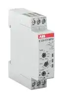
Analogue Timer, CT-D, Multifunction, 50 ms, 100 h, 7 Ranges, 1 Changeover Relay
- Manufacturer: ABB
- Product type: Analogue Timers - DIN Rail
- SVHC: To Be Advised
- Time Max: 100h
- Time Min: 50ms
- Timer Output: 1 Changeover Relay
- Product Range: CT-D
- Timer Functions: Multifunction
- Current Rating Nom: 6A
- Supply Voltage Max: 240VAC
- No. of Timing Ranges: 7Ranges
- Connection / Termination: Screw Terminals
| Delivery and price | |
|---|---|
| Units per pack | 1 |
| Price | 69.16 € |
| Current stock | 10+ |
| Lead time | 9 days |
**Data sheet**

## Electronic timer CT-MFD.12

## Multifunctional with 1 c/o (SPDT) contact

## The CT-MFD.12 is a multifunctional electronic

time relay. It is from the CT-D range.

With their MDRC profile and a width of only 17.5 mm, the CT-D range timers are ideally suited for installation in distribution panels as well as for industrial applications where compact dimensions are required.

**==> picture [5 x 51] intentionally omitted <==**

**----- Start of picture text -----**<br>
2CDC 251 089 F0006<br>**----- End of picture text -----**<br>


## Approvals

## Characteristics

- Rated control supply voltage 24-48 V DC, 24-240 V AC

- Multifunction timer with 7 timing functions: ON-delay, OFF-delay with auxiliary voltage, impulse-ON, impulse-OFF with auxiliary voltage, flasher starting with ON, flasher starting with OFF, pulse former

A UL 508, CAN/CSA C22.2 No.14 R EAC E CCC L RMRS

- 7 time ranges (0.05 s - 100 h) in one device

- Control input: voltage-related triggering, polarized, capable of switching a parallel load

- Light-grey enclosure in RAL 7035

Marks

a CE b RCM

- 1 c/o (SPDT) contact (250 V / 6 A)

- Width of only 17.5 mm (0.689 in)

- 2 LEDs for the indication of operational states

## Order data

|Order data|||||
|---|---|---|---|---|
|Type|Rated control supply voltage|Time range|Output|Order code|
|CT-MFD.12|24-48 V DC, 24-240 V AC|0.05 s - 100 h|1 c/o (SPDT) contact|1SVR 500 020 R0000|


Functions

Operating controls

**==> picture [200 x 8] intentionally omitted <==**

**----- Start of picture text -----**<br>
1  Rotary switch for the preselection of the time range<br>**----- End of picture text -----**<br>


- || 2 Potentiometer with direct reading scale for the fine adjustment of the time delay

- 3 Rotary switch for the selection of the timing function

- ." 4 Indication of operational states

   - U: green LED

**==> picture [219 x 135] intentionally omitted <==**

**----- Start of picture text -----**<br>
5<br>4€<br>1<br>om i<br>ooh. ‘ath 00m<br>4<br>2<br>gr<br>3<br>. a ai Q J<br>2CDC 251 089 F0006<br>**----- End of picture text -----**<br>


- V control supply voltage applied W timing R: yellow LED V output relay energized

- 5 Circuit diagram

## Application

With their structural form and their width of only 17.5 mm, the CT-D range timers are ideally suited for installation in distribution panels.

Multifunction timers are ideally suited for service and maintenance applications, because one device can replace a number of time relays with different functions, voltage and time ranges. This reduces inventory and saves money.

## Operating mode

The CT-MFD.12 has 1 c/o (SPDT) contact and provides 7 timing functions. The function is rotary switch selectable on the front of the unit. Each function is indicated by an international function symbol. One of 7 time delay ranges, from 0.05 s to 100 h, can be selected with another rotary switch. The fine adjustment of the time delay is made via an internal potentiometer, with a direct reading scale, on the front of the unit.

2 - Electronic timer CT-MFD.12 | Data sheet

Function descriptions / diagrams

## A ON-delay

This function requires continuous control supply voltage for timing. Timing begins when control supply voltage is applied. The green LED flashes during timing. When the selected time delay is complete, the output relay energizes and the flashing green LED turns steady. If control supply voltage is interrupted, the output relay de-energizes and the time delay is reset.

Control input A1-Y1/B1 is disabled when this function is selected.

**==> picture [339 x 94] intentionally omitted <==**

**----- Start of picture text -----**<br>
A1-A2<br>15-18<br>15-16<br>green LED<br>t < t<br>t = adjusted time delay<br>2CDC 252 035 F0207<br>**----- End of picture text -----**<br>


## B OFF-delay with auxiliary voltage

This function requires continuous control supply voltage for timing.

If control input A1-Y1/B1 is closed, the output relay energizes immediately. If control input A1-Y1/B1 is opened, the time delay starts. The green LED flashes during timing. When the selected time delay is complete, the output relay de-energizes and the flashing green LED turns steady.

If control input A1-Y1/B1 recloses before the time delay is complete, the time delay is reset and the output relay does not change state. Timing starts again when control input A1-Y1/B1 re-opens.

If control supply voltage is interrupted, the output relay de-energizes and the time delay is reset.

**==> picture [340 x 107] intentionally omitted <==**

**----- Start of picture text -----**<br>
A1-A2<br>A1-Y1/B1<br>15-18<br>15-16<br>green LED<br>t < t<br>t = adjusted time delay<br>2CDC 252 036 F0207<br>**----- End of picture text -----**<br>


## CA Impulse-ON

This function requires continuous control supply voltage for timing.

The output relay energizes immediately when control supply voltage is applied and de-energizes after the set pulse time is complete. The green LED flashes during timing. When the selected pulse time is complete, the flashing green LED turns steady.

If control supply voltage is interrupted, the output relay de-energizes and the time delay is reset.

Control input A1-Y1/B1 is disabled when this function is selected.

**==> picture [343 x 94] intentionally omitted <==**

**----- Start of picture text -----**<br>
A1-A2<br>15-18<br>15-16<br>green LED<br>t < t<br>t = adjusted pulse time<br>2CDC 252 037 F0207<br>**----- End of picture text -----**<br>


Data sheet | Electronic timer CT-MFD.12 - 3

CB Impulse-OFF with auxiliary voltage

This function requires continuous control supply voltage for timing.

If control supply voltage is applied, opening control input A1-Y1/B1 energizes the output relay immediately and starts timing. The green LED flashes during timing. When the selected pulse time is complete, the output relay de-energizes and the flashing green LED turns steady.

Closing control input A1-Y1/B1, before the time delay is complete, de-energizes the output relay and resets the time delay.

If control supply voltage is interrupted, the output relay de-energizes and the time delay is reset.

**==> picture [339 x 108] intentionally omitted <==**

**----- Start of picture text -----**<br>
A1-A2<br>A1-Y1/B1<br>15-18<br>15-16<br>green LED<br>t < t<br>t = adjusted pulse time<br>2CDC 252 038 F0207<br>**----- End of picture text -----**<br>


## DA Flasher, starting with ON

Applying control supply voltage starts timing with symmetrical ON & OFF times. The cycle starts with an ON time first. The ON & OFF times are displayed by the flashing green LED, which flashes twice as fast during the OFF time.

If control supply voltage is interrupted, the output relay de-energizes and the time delay is reset. Control input A1-Y1/B1 is disabled when this function is selected.

**==> picture [339 x 90] intentionally omitted <==**

**----- Start of picture text -----**<br>
A1-A2<br>15-18<br>15-16<br>green LED<br>t  t<br>t = adjusted flashing time<br>2CDC 252 031 F0207<br>**----- End of picture text -----**<br>


## DB Flasher, starting with OFF

Applying control supply voltage starts timing with symmetrical ON & OFF times. The cycle starts with an OFF time first. The ON & OFF times are displayed by the flashing green LED, which flashes twice as fast during the OFF time. If control supply voltage is interrupted, the output relay de-energizes and the time delay is reset. Control input A1-Y1/B1 is disabled when this function is selected.

**==> picture [339 x 90] intentionally omitted <==**

**----- Start of picture text -----**<br>
A1-A2<br>15-18<br>15-16<br>green LED<br>t  t<br>t = adjusted flashing time<br>2CDC 252 032 F0207<br>**----- End of picture text -----**<br>


4 - Electronic timer CT-MFD.12 | Data sheet

## H Pulse former

This function requires continuous control supply voltage for timing.

Closing control input A1-Y1/B1 energizes the output relay immediately and starts timing. Operating the control contact switch A1-Y1/B1 during the time delay has no effect. The green LED flashes during timing. When the selected ON time is complete, the output relay de-energizes and the flashing green LED turns steady. After the ON time is complete, it can be restarted by closing control input A1-Y1/B1.

If control supply voltage is interrupted, the output relay de-energizes and the time delay is reset.

**==> picture [339 x 105] intentionally omitted <==**

**----- Start of picture text -----**<br>
A1-A2<br>A1-Y1/B1<br>15-18<br>15-16<br>green LED<br>t t<br>t = adjusted pulse time<br>2CDC 252 039 F0207<br>**----- End of picture text -----**<br>


## Electrical connection

**==> picture [511 x 157] intentionally omitted <==**

**----- Start of picture text -----**<br>
A1-A2 Rated control supply voltage Us 24-48 V DC or 24-240 V AC<br>A1  15  Y1/B1 A1-Y1/B1 Control input<br>15-16/18 1 c/o (SPDT) contact<br>Y1/<br>B1 A1 15<br>A2  16  18<br>18  16  A2<br>Connection diagram<br>2CDC 252 114 F0b06<br>**----- End of picture text -----**<br>


## Wiring instructions

Parallel load to control input possible / allowed

**==> picture [183 x 139] intentionally omitted <==**

**----- Start of picture text -----**<br>
L(+)<br>A1 Y1/B1<br>A2<br>N(-)<br>2CDC 252 102 F0b06<br>**----- End of picture text -----**<br>


Data sheet | Electronic timer CT-MFD.12 - 5

## Technical data

Data at Ta = 25 °C and rated values, unless otherwise indicated

## Input circuits

**==> picture [511 x 537] intentionally omitted <==**

**----- Start of picture text -----**<br>
Supply circuit A1-A2<br>Rated control supply voltage Us 24-240 V AC, 24-48 V DC<br>Rated control supply voltage Us tolerance -15...+10 %<br>Typical current / power consumption 24 V DC 14 mA / 0.3 W<br>115 V AC 52 mA / 1.3 VA<br>230 V AC 60 mA / 2.4 VA<br>Rated frequency DC; 50/60 Hz<br>Frequency range AC 47-63 Hz<br>Power failure buffering time min. 20 ms<br>Release voltage > 10 % of the min. rated control supply voltage Us<br>Control circuit<br>Control input, control function A1-Y1/B1 start timing external<br>Kind of triggering voltage-related triggering<br>Resistance to reverse polarity yes<br>Polarized yes<br>Capable of switching a parallel load yes<br>Maximum cable length to the control inputs 50 m - 100 pF/m<br>Minimum control pulse length 20 ms<br>Control voltage potential see rated control supply voltage Us<br>Current /power consumption of the control  24 V DC 3.9 mA / 0.1 W<br>input  115 V AC 23.0 mA / 0.3 VA<br>230 V AC 26.0 mA / 0.7 VA<br>Timing circuit<br>Kind of timer Multifunction timer ON-delay, OFF-delay with auxiliary voltage, Impulse-ON, Impulse-OFF with<br>auxiliary voltage, Flasher, starting with ON, Flasher, starting with OFF,<br>Pulse former<br>Time ranges 0.05 s - 100 h 0.05-1 s, 0.5-10 s, 5-100 s, 0.5-10 min, 5-100 min, 0.5-10 h, 5-100 h<br>Recovery time < 50 ms<br>Repeat accuracy (constant parameters) D t < ± 0.5 %<br>Accuracy within the rated control supply voltage tolerance D t < 0.005 % / V<br>Accuracy within the temperature range D t < 0.06 % / °C<br>Setting accuracy of time delay ± 10 % of full-scale value<br>User interface<br>Indication of operational states<br>Control supply voltage / timing U: green LED V: control supply voltage applied<br>W: timing<br>Relay status R: yellow LED V: output relay energized<br>**----- End of picture text -----**<br>


6 - Electronic timer CT-MFD.12 | Data sheet

## Output circuit

**==> picture [512 x 250] intentionally omitted <==**

**----- Start of picture text -----**<br>
Kind of output 15-16/18 relay, 1 c/o (SPDT) contact<br>Contact material Cd-free<br>Rated operational voltage Ue 250 V<br>Minimum switching voltage / Minimum switching current 12 V / 100 mA<br>Maximum switching voltage / Minimum switching current see load limit curve / see load limit curve<br>Rated operational current Ie AC-12 (resistive) at 230 V 6 A<br>AC-15 (inductive) at 230 V  3 A<br>DC-12 (resistive) at 24 V  6 A<br>DC-13 (inductive) at 24 V  2 A<br>AC rating (UL 508) utilization category<br>B 300<br>(Control Circuit Rating Code)<br>max. rated operational voltage 300 V AC<br>maximum continuous thermal current at B 300 5 A<br>max. making/breaking apparent power at B 300 3600 VA / 360 VA<br>Mechanical lifetime 30 x 10 [6]  switching cycles<br>Electrical lifetime AC-12, 230 V, 4 A 0.1 x 10 [6]  switching cycles<br>Maximum fuse rating to achieve n/c contact 6 A fast-acting<br>short-circuit protection n/o contact 10 A fast-acting<br>**----- End of picture text -----**<br>


## General data

**==> picture [511 x 154] intentionally omitted <==**

**----- Start of picture text -----**<br>
MTBF on request<br>Duty time 100 %<br>Dimensions (W x H x D) product dimensions 17.5 x 70 x 58 mm (0.69 x 2.76 x 2.28 in)<br>packaging dimensions 89 x 65 x 20 mm (3.50 x 2.56 x 0.79 in)<br>Weight 0.06 kg (0.132 lb)<br>Mounting DIN rail (IEC/EN 60715), snap-on mounting without any tool<br>Mounting position any<br>Minimum distance to other units, horizontal not necessary<br>normal operation mode vertical not necessary<br>Degree of protection housing IP50<br>terminals IP20<br>**----- End of picture text -----**<br>


## Electrical connection

**==> picture [511 x 180] intentionally omitted <==**

**----- Start of picture text -----**<br>
Connecting capacity fine-strand with wire end ferrule 2 x 0.5-1.5 mm [2]  / 1 x 0.5-2.5 mm [2]  (2 x 20-16 AWG / 1 x 20-14 AWG)<br>fine-strand without wire end ferrule 2 x 0.5-1.5 mm [2]  / 1 x 0.5-2.5 mm [2]  (2 x 20-16 AWG / 1 x 20-14 AWG)<br>rigid 2 x 0.5-1.5 mm [2]  / 1 x 0.5-4 mm [2]  (2 x 20-16 AWG / 1 x 20-12 AWG)<br>Stripping length 7 mm (0.28 in)<br>Tightening torque 0.5-0.8 Nm (4.43-7.08 lb.in)<br>Environmental data<br>Ambient temperature ranges operation -20...+60 °C (-4...+140 °F)<br>storage -40...+85 °C (-40...+185 °F)<br>Climatic class (IEC/EN 60068-2-30) 3k3<br>Relative humidity range 25 % to 85 %<br>Vibration, sinusoidal (IEC/EN 60068-2-6) 20 m/s [2] , 10 cycles, 10...150...10 Hz<br>Shock, half-sine (IEC/EN 60068-2-27) 150 m/s [2] , 11 ms<br>**----- End of picture text -----**<br>


Data sheet | Electronic timer CT-MFD.12 - 7

Isolation data

**==> picture [511 x 420] intentionally omitted <==**

**----- Start of picture text -----**<br>
Rated insulation voltage Ui input circuit / output circuit 300 V<br>output circuit 1 / output circuit 2 n/a<br>Rated impulse withstand voltage Uimp between all isolated circuits  4 kV; 1.2/50 μs<br>Power-frequency withstand voltage between all isolated circuits  2.5 kV, 50 Hz, 60 s<br>(test voltage)<br>Basic insulation (IEC/EN 61140) input circuit / output circuit 300 V<br>Protective separation   input circuit / output circuit<br>250 V<br>(IEC/EN 61140, EN 50178)<br>Pollution degree 3<br>Overvoltage category III<br>Standards / Directives<br>Standards IEC/EN 61812-1<br>Low Voltage Directive 2014/35/EU<br>EMC directive 2014/30/EU<br>RoHS Directive 2011/65/EC<br>Electromagnetic compatibility<br>Interference immunity to IEC/EN 61000-6-2<br>electrostatic discharge IEC/EN 61000-4-2 Level 3 (6 kV / 8 kV)<br>radiated, radio-frequency,  IEC/EN 61000-4-3 Level 3 (10 V/m)<br>electromagnetic field<br>electrical fast transient / burst  IEC/EN 61000-4-4 Level 3 (2 kV / 5 kHz)<br>surge IEC/EN 61000-4-5 Level 3 (2 kV L-L)<br>conducted disturbances, induced by   IEC/EN 61000-4-6 Level 3 (10 V)<br>radio-frequency fields<br>Interference emission IEC/EN 61000-6-3<br>high-frequency radiated IEC/CISPR 22, Class B<br>EN 55022<br>high-frequency conducted IEC/CISPR 22, Class B<br>EN 55022<br>**----- End of picture text -----**<br>


8 - Electronic timer CT-MFD.12 | Data sheet

Technical diagrams

## Load limit curves

**==> picture [432 x 378] intentionally omitted <==**

**----- Start of picture text -----**<br>
resistive load resistive load<br>AC current [A] DC current [A]<br>AC load (resistive)  DC load (resistive)<br>1.0<br>0.9<br>0.8<br>0.7 250 V<br>resistive load<br>0.6<br>0.5<br>0.1 0.2 0.3 0.4 0.5 0.6 0.7 0.8 0.9 1.0<br>cos ϕ Switching current [A]<br>AC voltage [V] DC voltage [V]<br>2CDC 252 044 F0207 2CDC 252 045 F0207<br>Derating factor F Switching cycles<br>2CDC 252 124 F0206 2CDC 252 123 F0206<br>**----- End of picture text -----**<br>


Derating factor F for inductive AC load

Contact lifetime

Data sheet | Electronic timer CT-MFD.12 - 9

Dimensions

## in mm and _inches_

**==> picture [255 x 190] intentionally omitted <==**

**----- Start of picture text -----**<br>
58 2.28“<br>0.69“ 0.2“<br>17,5 5 43,4 1.71“<br>2.76“ 1.77“<br>70 45<br>2CDC 252 131 F0b06<br>**----- End of picture text -----**<br>


## Further documentation

**==> picture [511 x 43] intentionally omitted <==**

**----- Start of picture text -----**<br>
Document title Document type Document number<br>Electronic products and relays Technical catalogue 2CDC 110 004 C02xx<br>CT-D range Instruction manual 1SVC 500 010 M1000<br>**----- End of picture text -----**<br>


You can find the documentation on the internet at www.abb.com/lowvoltage

-> Automation, control and protection -> Electronic relays and controls -> Electronic timers.

## CAD system files

- You can find the CAD files for CAD systems at http://abb-control-products.partcommunity.com -> Low Voltage Products & Systems -> Control Products -> Electronic Relays and Controls.

10 - Electronic timer CT-MFD.12 | Data sheet

## Contact us

ABB STOTZ-KONTAKT GmbH P. O. Box 10 16 80 69006 Heidelberg, Germany Phone: +49 (0) 6221 7 01-0 Fax: +49 (0) 6221 7 01-13 25 E-mail: info.desto@de.abb.com

You can find the address of your local sales organisation on the ABB home page http://www.abb.com/contacts -> Low Voltage Products and Systems

## Note:

We reserve the right to make technical changes or modify the contents of this document without prior notice. With regard to purchase orders, the agreed particulars shall prevail. ABB AG does not accept any responsibility whatsoever for potential errors or possible lack of information in this document.

We reserve all rights in this document and in the subject matter and illustrations contained therein. Any reproduction, disclosure to third parties or utilization of its contents – in whole or in parts – is forbidden without prior written consent of ABB AG.

Copyright© 2016 ABB All rights reserved
Updated at June 3, 2026
ABB is a global leader in power and automation technologies, recognized for delivering innovative solutions that improve performance while minimizing environmental impact. Serving a diverse range of sectors including industrial processing, OEM, and building services, ABB provides highly reliable components designed to meet the rigorous demands of modern electrical systems. The company is particularly renowned for its advanced circuit protection solutions. This includes a comprehensive selection of thermal magnetic circuit breakers, alongside specialized RCBO, RCD, GFCI, and AFDD circuit breakers. These foundational safety components are supported by a wide array of high-quality fuse holders and circuit breaker accessories, ensuring complete protection for complex industrial and commercial installations. Beyond circuit protection, ABB excels in automation and process control. Their offering features sophisticated visual signal indicator units, industrial switch accessories, and panel instrumentation designed for intuitive system monitoring. Additionally, ABB manufactures a robust range of power relays, safety relays, and AC/DC converters, providing engineers with the critical building blocks needed for efficient, secure, and reliable control panels.
About Novapart
Novapart is a B2B electronic component broker specialising in stock shortages and cost reduction. We source hard-to-find parts and identify compliant alternatives across a catalogue of 410,000+ components from 500+ manufacturers.
Learn more →Stock Shortage Specialist
When a component is unavailable, discontinued or has an unacceptable lead time, we tap into our network of vetted European and Asian distributors to source what you need — without compromising on quality or traceability.
Request a quote →Compliant Alternatives
We identify pin-to-pin, electrically equivalent substitutes that meet the same certifications (RoHS, AEC-Q100, REACH) as your original specification — validated against datasheets, not just part numbers. Often at a lower cost.
BOM Analysis service →